LSQ-STAR-800Satellite Tracking and Reporting System
Attenti
Click to zoom
Application Details
- Equipment Class
- CYY - Communications Receiver used w/Pt 15 Transmitter
- Date of Grant
- Jun 19, 2003
- Application Purpose
- Original Equipment
- Date of Application
- Jun 16, 2003
- Equipment Note
- Satellite Tracking and Reporting System
- Frequency Range
- 318.00000000 - 318.00000000
- Company
- Attenti
- Country
- Israel
Documents & Files
Document Text
Text extracted from the exhibit documents filed with the FCC. Open a document above to read the original.
Users Manual
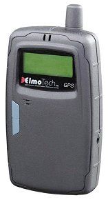
ElmoTech Ltd. Version 1.0 STAR UNIT User MANUAL Version 1.0 May 2003 EMS2000i STaR Unit User Manual 1 Version 1.0 ElmoTech Ltd. EMS2000i STaR Unit User Manual 2 Prepared by: Elmo-Tech Ltd. Corporate Headquarters 2 Rehov HaBarzel P.O. Box 13236 Ramat HaChayal 61132 Tel Aviv Israel Tel: +972-3 – 6478871 Fax: +972-3 – 6478872 Visit us at: www.elmotech.com © 2001, Elmo Tech Ltd. All rights reserved. No part of this publication may be reproduced, stored in a retrieval system, or transmitted in any form or by any means, electronic, mechanical, photocopying, recording or otherwise, for purpose other than the user’s manual, without prior permission of Elmo Tech Ltd. NO WARRANTY The technical documentation is being delivered AS-IS, and ElmoTech Ltd. makes no warranty as to its accuracy or use. Any use of the technical documentation or the information contained therein is at risk of the user. Documentation may include technical or other inaccuracies or typographical errors. ElmoTech Ltd. Reserves the right to make change without prior notice. ElmoTech Ltd. Version 1.0 EMS2000i STaR Unit User Manual 3 Table of Contents Section Page THE MONITOR CENTER/ PROBATION AGENCY________________ 6 Equipment________________________________________________ 6 THE OFFENDER’S PREMISES_____________________________ 8 Monitoring System Location_________________________________ 8 Activating the STaR Unit___________________________________ 9 Downloading the Curfew Schedule and Default Offender Parameters11 Installing the Transmitter__________________________________ 12 Calibrating the Transmitter________________________________ 12 Attaching the Transmitter_________________________________ 13 STaR Unit Range Setting__________________________________ 15 General Rules for the Offender______________________________ 18 REMOVING The Monitoring System____________________________ 19 Initiating an End of Service_________________________________ 19 Deactivating the STaR Unit_________________________________ 19 Removing the Transmitter_________________________________ 20 Disconnecting the Transmitter______________________________ 20 TRANSMITTER CLEANING INSTRUCTIONS__________________ 22 Cleaning the Transmitter:__________________________________ 22 Transmitter strap replacement_________________________________ 23 Reasons for Strap Replacement_____________________________ 23 Version 1.0 ElmoTech Ltd. EMS2000i STaR Unit User Manual 4 Equipment Needed for Strap Replacement____________________ 24 Replacing the Transmitter Straps___________________________ 24 FCC Notices________________________________________________ 26 STaR Unit FCC Notices__________________________________ 26 STaR Unit Customer Information___________________________ 27 Transmitter FCC Notices__________________________________ 27 ElmoTech Ltd. Version 1.0 EMS2000i STaR Unit User Manual 5 Table of Figures Figure Page FIGURE 1 IDEAL HOME UNIT LOCATION........................................................ 8 F IGURE 2 THE STAR UNIT........................................................................... 10 F IGURE 3 PROTRUDING SIDE OF TRANSMITTER DIRECTED UPWARDS.......... 14 Version 1.0 ElmoTech Ltd. THE MONITOR CENTER/ PROBATION AGENCY At the Monitor Center/Probation Agency: 1. Enter the Offender’s data in the monitoring application. This can be done well in advance, even before the actual equipment is allocated and installed. 2. Enter the following equipment data in the monitoring application. • STaR unit Serial No. - Check that the number entered matches the number on the STaR unit. • Transmitter Serial No. - Check that the number entered matches the number on the Transmitter. The STaR Unit/Transmitter Serial No.’s are visible on the back of each unit. Equipment Check that you have all the required equipment: • STaR unit, carrying pouch and power adapter • Transmitter • Home Unit • Electronic key • Locking device • Strap holder • Strap clips (male and female) EMS2000i STaR Unit User Manual 6 ElmoTech Ltd. Version 1.0 • Screwdriver (to open a clip if necessary). It is recommended to use a 5 mm flat head screwdriver. It is always advisable to bring an extra set of strap clips to cater for the event in which the first set may be accidentally damaged during the installation. EMS2000i STaR Unit User Manual 7 Version 1.0 ElmoTech Ltd. THE OFFENDER’S PREMISES Monitoring System Location In order to install the Monitoring System, you will need to find the best location for the Home Unit. The ideal place for the Home Unit is in the center of the house, 3 feet off the ground and at least 1 foot away from the wall. Figure 1 Ideal Home Unit Location The Home Unit should be placed in an open area away from other electrical appliances, personal computers, laptops or metal objects. EMS2000i STaR Unit User Manual 8 ElmoTech Ltd. Version 1.0 EMS2000i STaR Unit User Manual 9 The STaR unit should be placed in the proximity of not more than 15 feet from the Home Unit, and should be connected to the charger when at home. Activating the STaR Unit In order to activate the STaR unit: 1. Connect the charger (power adapter) to the wall socket. 2. Plug the appropriate end of the charger cord into the charger socket on right side of the STaR unit. 3. The STaR unit makes an audible beeping sound and the STaR logo and version number briefly appear on the LCD. At this stage the unit runs through an initial series of Built-In-Tests (BIT). 4. After completing the tests the LCD will display the default STaR message, indicating that the STaR unit is in a working state. Version 1.0 ElmoTech Ltd. Antenna LED Indicators LCD Panel Acknowledge and LCD Backlight Buttons Charger Socket Figure 2 The STaR Unit If, at the end of the start-up self test, audible beeping sounds are heard and both the LED’s flash for 10 seconds, it could indicate one of the following possible failures: ● Case open micro-switch malfunction ● Range threshold values lost (maximum reception range is used in this case). EMS2000i STaR…
Text truncated - open the document above for the full version.
Cover Letter(s)
TCB Confidentiality Form 04/06/2003 EMCCert DR. RAŠEK Boelwiese 5 91320 Ebermannstadt Germany Tel.: +49-9194-9331 Fax: +49-9194-7964-84 E-mail: [email protected] URL: http://www.emcc.de Gentlemen: This letter is to comply with Section 0.457(d)(2)(i) pertaining to confidential material. Elmo Tech would like the following document regarding this submission for FCC ID: LSQ-STaR-800 to be kept confidential. Schematics: 1 Page. The above material contains trade secrets or technical data, which would customarily be guarded from competitors. We do not want this document to be accessible to the general public. Sincerely, Gil Gemer VP R&D
ID Label/Location Info
Label Location LSQ-STAR-800
Operational Description
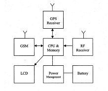
STAR UNIT Operational Description Version 1.0 May 2003 Prepared by: Elmo-Tech Ltd. Corporate Headquarters 2 Rehov HaBarzel P.O. Box 13236 Ramat HaChayal 61132 Tel Aviv Israel Tel: +972-3 – 6478871 Fax: +972-3 – 6478872 Visit us at: www.elmotech.com © 2001, Elmo Tech Ltd. All rights reserved. No part of this publication may be reproduced, stored in a retrieval system, or transmitted in any form or by any means, electronic, mechanical, photocopying, recording or otherwise, for purpose other than the user’s manual, without prior permission of Elmo Tech Ltd. NO WARRANTY The technical documentation is being delivered AS-IS, and ElmoTech Ltd. makes no warranty as to its accuracy or use. Any use of the technical documentation or the information contained therein is at risk of the user. Documentation may include technical or other inaccuracies or typographical errors. ElmoTech Ltd. Reserves the right to make change without prior notice. Dmatek Ltd CONFIDENTIAL Ver.1.0 TABLE OF CONTENTS General 1 Software management modules 1 STAR modes 2 Off mode 2 Setup mode 2 On mode 3 First time 3 Pre program 3 Live 3 Post program 3 Malfunction 4 Live sub-modes 4 Charge 4 Home 4 Save power (low battery) 4 First fix 5 Normal 5 Discovery 5 IDNT (Identification) 5 Relax (No motion with GPS) 6 TABLE OF FIGURES FIGURE 1 - STAR MODES TREE......................................................................................2 TABLE OF TABLES TABLE 1 - STAR MANAGEMENT MODULES....................................................................1 T ABLE 2 - MANAGEMENT MODULES AVAILABILITYERROR! BOOKMARK NOT DEFINED. STAR Operational Description Manual iii of iii ElmoTech Ltd. Version 1.0 STAR Operational Description Manual 1 GENERAL The STAR will turn off in one of the following cases: 1. The STAR will shut itself down due to low battery detection. 2. The STAR can be manually shut off by pressing the reset button with external power disconnected (Can be done only by official support officer and can be exclusively blocked). The moment that the STAR is turned on, its internal modes of operation are decided by the STAR according to its internal logic. SOFTWARE MANAGEMENT MODULES The following modules will selectively be active/not active according to the STAR mode of operation. Later in this document it will be specified whether the module is active or not for each mode (or sub mode). Table 1 - STAR management modules Module name Description Power control Control the STAR battery power, start and stop charging and external power control. Monitoring Control the GPS modes; decide when to log GPS points. Schedule/Zones Manage the zones in/out violations according to each zone schedule and type. MMI Control the LCD, Leds and buzzer. Response to user button’s pressings. Navigation Averaging the received position and perform geographical calculations. Version 1.0 ElmoTech Ltd. STAR MODES The following figure describes the entire STAR modes of operations: Figure 1 - STAR modes tree Off Off Setup Setup On On First time First time Pre Program Pre Program Live Live Post Program Post Program Charge Charge Home Home Save power Save power First Fix First Fix Normal Normal Discover y Discovery IDNT Off Off Setup Setup On On First time First time Pre Program Pre Program Live Live Post Program Post Program Charge Charge Home Home Save power Save power First Fix First Fix Normal Normal Discover y Discovery IDNT Malfunction Malfunction Malfunction Malfunction IDNT Relax Relax IDNT Relax Relax Off mode The STAR is turned off, the battery is not charging and the GPS is supplied with power from the backup battery to save last known GPS parameters (may be disabled by a jumper during storage). Setup mode The STAR is turned on, initialize parameters and load data from the non-volatile memory (flash and E2PROM) to its internal RAM. The STAR will check vital components usability (BIT) to detect component’s malfunctions (GPS, GSM, RTC, Flash). STAR Unit Operational Description 2 ElmoTech Ltd. Version 1.0 STAR Operational Description Manual 3 On mode The On mode is initiated immediately after setup termination. On mode is divided to five sub-modes as detailed below: First time First time sub mode is the initial activation mode where the STAR is actually blind and does not have any parameter to operate (there are no parameters to perform monitoring). Pre program The pre program sub-mode is generated upon STAR setting parameters availability and before the time of the start program. The STAR will shut itself down upon external power disconnection. Live Live mode is generated if the parameters were downloaded successfully and the current time is between the start and the end program. See later herein (Live sub-modes) a detailed description for each of the live sub-modes. Post program The post program sub-mode is generated upon STAR setting parameters availability and post the time of the end program. The STAR will shut himself down upon external power disconnection. Version 1.0 ElmoTech Ltd. STAR Unit Operational Description 4 The STAR is listening to incoming rings all the time attempting to establish a DCC connection. Malfunction In this mode one of the vital STAR components is out of order and the STAR can not functioning properly (GSM failure, RTC failure, Memory failure). If this mode happens it needs a technical support interfering to fix it. Live sub-modes Charge The STAR is in charge mode (external power is connected) without home detection. Home The STAR is in charge mode (external power is connected) with home detection. Save power (low battery) The battery power is detected below the normal operational power and thus the GPS will remain off. In this mode only vital components operate, in order to save battery as long as possible. ElmoTech Ltd. Version 1.0 STAR Operational Description Manual 5 First fix This mode starts when the GPS position is required after a long time with GPS off (May starts immediately after power up or after any mode that…
Text truncated - open the document above for the full version.
Test Report
REV ∆ Description Sheet Effected Date Drawn Checked A 17.06.03 D.Lanuel S.Cohen EMC Laboratory Satellite Tracking and Reporting System FCCID :LSQ-STAR-800 Manufactured by Elmotech Ltd. EMC Test Report According FCC Part 15 Requirements JUNE 2003 Function/Title Name Signature Date Prepared by Test Engineer D.Lanuel 17.06.03 Approved by EMC Lab. Manager S.Cohen 17.06.03 STaR Unit EMI Test Report Table of Contents Para Page 1 TEST DATA INFORMATION...................................................................................................................3 A. DESCRIPTION OF EQUIPMENT UNDER TEST......................................................................................3 B. APPLICANT INFORMATION: ..........................................................................................................3 C. TEST PERFORMANCE: ..................................................................................................................3 2 TEST SUMMARY AND SIGNATURES.......................................................................................................4 A. TEST PERFORMED BY: ..................................................................................................................4 B. TEST REPORT PREPARED BY: ........................................................................................................4 C. TEST REPORT APPROVED BY:........................................................................................................4 3 GENERAL INFORMATION......................................................................................................................5 A. SPECIFICATION REFERENCE.........................................................................................................5 B. APPLICABLE DOCUMENTS.............................................................................................................5 4 ADMINISTRATIVE DATA.......................................................................................................................6 A. SCOPE......................................................................................................................................6 B. ADMINISTRATIVE DATA...............................................................................................................6 C. CERTIFICATION AND QUALIFICATIONS...........................................................................................6 D. MEASUREMENT REPEATABILITY INFORMATION.................................................................................6 E. MEASURING EQUIPMENT CALIBRATION..........................................................................................7 F. ANTENNAS CALIBRATION.................................................................................................................7 5 E.U.T INFORMATION............................................................................................................................7 A. E.U.T DESCRIPTION...................................................................................................................7 B. E.U.T BLOCK DIAGRAM...............................................................................................................7 C. E.U.T TEST CONFIGURATION.......................................................................................................8 D. E.U.T MODE OF OPERATION DESCRIPTION.....................................................................................8 6 OUT OF BAND RADIATED FIELD STRENGTH MEASUREMENT TEST ACCORDING TO 15.109......................9 A. GENERAL.................................................................................................................................. 9 B. TEST RESULTS SUMMARY & CONCLUSIONS.....................................................................................9 C. LIMITS OF RADIATED INTERFERENCE FIELD STRENGTH ACCORDING 15.109........................................9 D. TEST INSTRUMENTATION AND EQUIPMENT....................................................................................10 E. PRELIMINARY TEST PROCEDURE.................................................................................................12 F. PRELIMINARY RESULTS.................................................................................................................13 7 FINAL RADIATED INTERFERENCE FIELD STRENGTH EASUREMENT........................................................23 A. TEST INSTRUMENTATION AND EQUIPMENT....................................................................................23 B. TEST SETUP.............................................................................................................................23 C. FINAL TEST RESULTS................................................................................................................25 8 CONDUCTED EMISSIONS, AC POWER LEADS ACCORDING TO FCC 15.107.............................................26 A. EQUIPMENT UNDER TEST DESCRIPTION AND OPERATION................................................................26 B. TEST RESULTS SUMMARY & CONCLUSIONS...................................................................................26 C. LIMITS OF CONDUCTED EMISSION AT MAINS TERMINALS................................................................26 D. TEST INSTRUMENTATION AND EQUIPMENT....................................................................................26 E. TEST SETUP.............................................................................................................................27 F. TEST PROCEDURE.........................................................................................................................30 EMC/30020FC03054 2/40 STaR Unit EMI Test Report 1 TEST DATA INFORMATION a. Description of equipment Under Test. Equipment Under Test: Satellite Tracking and Reporting System FCCID LSQ-STAR-800 Manufacturer: Elmotech Ltd. Serial Num…
Text truncated - open the document above for the full version.
Contact Information
Applicant
Yossi Murciano(Quality Assurance Manager)
Test Firm
Elbit Systems Land C41Tadiran Ltd.Samuel Cohen
Technical Specifications
| # | Rule Parts | Frequency Range | Power Output |
|---|---|---|---|
| 1 | 15B | 318 MHz - 318 MHz | - |
Other Applications from Attenti

LSQ-E4-RF-2
Sep 02, 2012Dual Comm RF Monitoring System
Equipment Class
DSR - Part 15 Remote Control/Security Device Transceiver
LSQ-TRXS-860-2
Nov 13, 2011Wrist Tag
Equipment Class
DSR - Part 15 Remote Control/Security Device Transceiver
LSQ-TRXS-860
Nov 13, 2011Wrist Tag
Equipment Class
DSR - Part 15 Remote Control/Security Device Transceiver
LSQTRX900F2
Nov 06, 2011Part 15 - Remote Control / Security Device Transceiver
Equipment Class
DSR - Part 15 Remote Control/Security Device Transceiver
LSQ-SBU2000318
Aug 02, 20112TRACK BASE UNIT 318 MHz
Equipment Class
DSR - Part 15 Remote Control/Security Device Transceiver