LV3RF24RF24 RADIO TRANSCEIVER MODULE
Digitrax Inc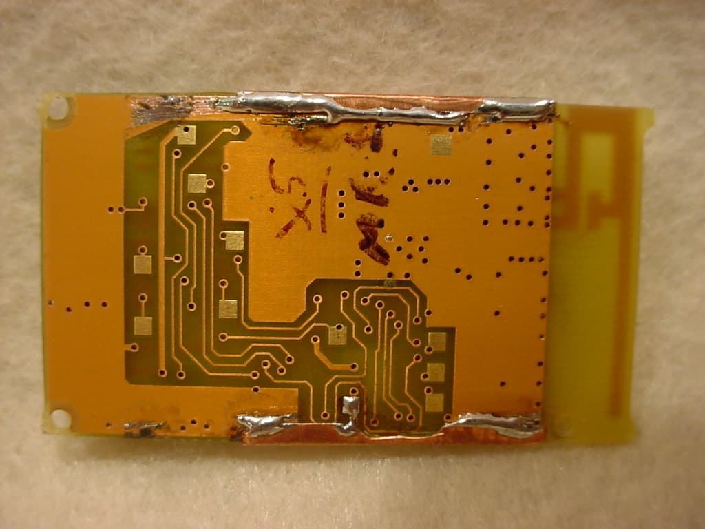
Click to zoom
Application Details
- Equipment Class
- DXX - Part 15 Low Power Communication Device Transmitter
- Date of Grant
- Aug 07, 2007
- Application Purpose
- Original Equipment
- Date of Application
- Aug 07, 2007
- Equipment Note
- RF24 RADIO TRANSCEIVER MODULE
- Frequency Range
- 2405.00000000 - 2480.00000000
- Company
- Digitrax Inc
- Country
- United States
Documents & Files
Document Text
Text extracted from the exhibit documents filed with the FCC. Open a document above to read the original.
Users Manual
5015 B.U. Bowman Drive Buford, GA 30518 USA Voice: 770-831-8048 Fax: 770-831-8598 Transceiver Certification Test Report FCC ID: LV3RF24 IC: 3015A-RF24 FCC Rule Part: 15.249 IC Standards Specification: RSS-210 ACS Report Number: 07-0262-15C Manufacturer: Digitrax Inc. Model: RF24 Installation Guide RF24 F F e e a a t t u u r r e e s s : : nDuplex LocoNet RF Module for Digitrax Host devices nFCC Part 15, Class B RFI compliant P P a a r r t t s s L L i i s s t t 1 RF24 Radio Module1 This Instruction sheet I I n n s s t t a a l l l l a a t t i i o o n n 1 Align RF24 module with 10 pin socket facing and matching the Host device plug orientation at the board edge. 2 Plug in the RF24, ensuring that the 10 pins of the socket exactly align with the 10 pin Host connector 3 Apply power to the Host, and the RF24 module will be recognized and oper- ate. That is all that is required to install this Plug N’Play device! 4. If the RF24 green LED does not blink when power is applied, contact Digitrax Techical support. ©2007 Digitrax, Incwww.digitrax.com1 D D i i g g i i t t r r a a x x C C o o m m m m a a n n d d C C o o n n t t r r o o l l R R u u n n Y Y o o u u r r T T r r a a i i n n s s , , N N o o t t Y Y o o u u r r T T r r a a c c k k ! ! RF24 Radio Transceiver Module 2.4 GHz Duplex Communications Module Fits Digitrax Host Devices 80 foot range Plug N’ Play Installation 2mm 10 Pin connector RF24 Module Digitrax Host Device FCC/IC Info Label Made in U.S.A. 307-RF24 -INS 1k/06/07 RF24 Transceiver Module Fits Digitrax Host Devices 450 Cemetery Street Norcross, GA USA 30071 www.digitrax.com T770-441-7992 F770-441-0759 [email protected] Warning: Changes or modifications to this device not expressly approved by Digitrax Inc. could void the user’s authority to operate the equipment. FCC Information: (FCC Module ID: LV3RF24) This equipment has been tested and found to comply with the limits for a class B digital device, pursuant to Part 15 of the FCC Rules. These limits are designed to provide reasonable protection against harmful interference in a residential instal- lation. This equipment generates, uses, and can radiate radio frequency energy and, if not installed and used in accordance with these instructions, may cause harmful interference to radio communications. However, there is no guarantee that interference will not occur in a particular installation. If this equipment does cause harmful interference to radio or television reception, which can be deter- mined by turning the equipment off and on, the user is encouraged to try to cor- rect the interference by one or more of the following measures: nReorient or relocate the receiving antenna nIncrease the seperation between the equipment and the receiver nConnect the equipment into an outlet on a circuit different from that to which the receiver in connected nConsult a dealer on an experienced radio/TV technician for help. Industry Canada Information: (IC ID: 3015A-RF24) This Class B digital apparatus meets all requirements of the Canadian Interference Causing Equipment Regulations. Operation is subject to the follow- ing two conditions: (1) this device may not cause harmful interference, and (2) this device must accept any interference received, including interference that may cause undesired operation. Cet appareillage numérique de la classe B répond à toutes les exigences de l'in- terférence canadienne causant des règlements d'équipement. L'opération est sujette aux deux conditions suivantes: (1) ce dispositif peut ne pas causer l'inter- férence nocive, et (2) ce dispositif doit accepter n'importe quelle interférence reçue, y compris l'interférence qui peut causer l'opération peu désirée. This class B digital apparatus complies with Canadian ICES-003. Cet appareillage numérique de la classe B est conforme à la norme NMB-o003 du Canada
Cover Letter(s)
450 S CEMETERY ST SUITE 206 NORCROSS GA USA 30071-4228 (770) 441-7992 FAX (770) 441-0759 Date: June 7 th 2007 CONFIDENTIALITY REQUEST Federal Communications Commission Equipment Authorization Branch 7435 Oakland Mills Road Columbia, MD 21046 Gentlemen: Digitrax Inc,respectfully requests confidentiality of certain materials provided with the submission of the RF24 under FCC ID: LV3RF24 in accordance with FCC Regulations 0.459. The confidentiality request applies to: 1. System block diagram (07-0262 – System Block Diagram.pdf) 2. Schematic drawings (07-0262 – Schematics.pdf) 3. Bills of materials and parts lists (07-0262 – Parts List.pdf) 4. Theory of operation (07-0262 – Theory of Operation.pdf) The RF24 has been developed at considerable effort and expense by Digitrax Inc. These items are considered as Trade Secrets and therefore public access to the proprietary material could possible result in duplication of equipment that could severely damage the company's business advantage. I appreciate your assistance in this matter. Sincerely, Name: AJ Ireland Signature: Title: VP Engineering
Cover Letter(s)
450 S CEMETERY ST SUITE 206 NORCROSS GA USA 30071-4228 (770) 441-7992 FAX (770) 441-0759 Thursday, June 21, 2007 Re: DA 00-1407/RSS-Gen - Modular Approval Request for Digitrax RF24 Gentlemen: Digitrax Inc. believes the RF24 meets the FCC requirements of DA 00-1407 and IC requirements of RSS-Gen for Modular Approval based on the following inherent design characteristics and the testing results included elsewhere in this application. The following information indicates how the numbered requirements of FCC DA 00-1407, RSS-Gen by similarity, are met. 1. The modular transmitter complies with item (1) of DA 00-1407 using an RF shielding enclosure soldered so as to cover and shield the RF, CPU and reference oscillator sections. 2. The RF24 employs voltage-tolerant 74HCT08 input buffers for the data-input line buffering of interface voltage levels. Additionally the hardware input lines do not directly control the modulation levels or rates, since these are configured by the onboard CPU, using a host handshake serial-data format on the input lines. 3. The RF24 employs 1% accurate low-noise voltage regulators for all the onboard electronics 4. The RF24 employs an integrated PCB antenna with no installation or user adjustability. 5. The RF24 has a special selectable Test mode to allow the FCC testing of the module Transmitter and Receiver, stand-alone without the need for a Digitrax Host device. The only connection needed is a DC power pack and a SPST switch for Test mode selection. This mode is not accessible to users. The RF24 meets FCC Conducted radiation limits as tested in a typical host device and does not use any ferrites or similar in its direct Host plug-in connection. 6. The RF24 has the required FCC ID label attached on the non-component side at manufacture. A copy of this label is included in this application. A sample label for the host device indicating the FCC ID of the integrated module is also provided in this filing. 7. The modular transmitter complies with any specific rules or operating requirements that ordinarily apply to a complete transmitter and adequate instructions are provided along with the module to explain any such requirements. A copy of these instructions are included in the application for equipment authorization. 8. The RF24 is a low-power device which transmits at less than 1 milliwatt (0dBm) so is not a radiation exposure hazard to users. Additionally the Host device configuration contains the RF24 and helps ensure a separation from the users’ body. The RF24 is designed to connect to Digitrax Host devices, and in this way the installation, usage and performance of this product can be maintained to comply with regulatory requirements such that the final configuration remains compliant. Sincerely, Name: AJ Ireland Signature: Title: VP Engineering
External Photos
5015 B.U. Bowman Drive Buford, GA 30518 USA Voice: 770-831-8048 Fax: 770-831-8598 Transceiver Certification Test Report FCC ID: LV3RF24 IC: 3015A-RF24 FCC Rule Part: 15.249 IC Standards Specification: RSS-210 ACS Report Number: 07-0262-15C Manufacturer: Digitrax Inc. Model: RF24 Internal Photographs Model: RF24 FCC ID: LV3RF24 IC: 3015A-RF24 5015 B.U. Bowman Drive Buford, GA 30518 USA Voice: 770-831-8048 Fax: 770-831-8598 Figure 1: RF24 Front View - Shield Model: RF24 FCC ID: LV3RF24 IC: 3015A-RF24 5015 B.U. Bowman Drive Buford, GA 30518 USA Voice: 770-831-8048 Fax: 770-831-8598 Figure 2: RF24 Front View – No Shield Model: RF24 FCC ID: LV3RF24 IC: 3015A-RF24 5015 B.U. Bowman Drive Buford, GA 30518 USA Voice: 770-831-8048 Fax: 770-831-8598 Figure 3: RF24 Back View
ID Label/Location Info
5015 B.U. Bowman Drive Buford, GA 30518 USA Voice: 770-831-8048 Fax: 770-831-8598 Transceiver Certification Test Report FCC ID: LV3RF24 IC: 3015A-RF24 FCC Rule Part: 15.249 IC Standards Specification: RSS-210 ACS Report Number: 07-0262-15C Manufacturer: Digitrax Inc. Model: RF24 Label Information Model: RF24 FCC ID: LV3RF24 IC: 3015A-RF24 5015 B.U. Bowman Drive Buford, GA 30518 USA Voice: 770-831-8048 Fax: 770-831-8598 Figure 1: RF24 Label Model: RF24 FCC ID: LV3RF24 IC: 3015A-RF24 5015 B.U. Bowman Drive Buford, GA 30518 USA Voice: 770-831-8048 Fax: 770-831-8598 Figure 2: RF24 Label Location Figure 3: Sample Host Label
Internal Photos
5015 B.U. Bowman Drive Buford, GA 30518 USA Voice: 770-831-8048 Fax: 770-831-8598 Transceiver Certification Test Report FCC ID: LV3RF24 IC: 3015A-RF24 FCC Rule Part: 15.249 IC Standards Specification: RSS-210 ACS Report Number: 07-0262-15C Manufacturer: Digitrax Inc. Model: RF24 Internal Photographs Model: RF24 FCC ID: LV3RF24 IC: 3015A-RF24 5015 B.U. Bowman Drive Buford, GA 30518 USA Voice: 770-831-8048 Fax: 770-831-8598 Figure 1: RF24 Front View - Shield Model: RF24 FCC ID: LV3RF24 IC: 3015A-RF24 5015 B.U. Bowman Drive Buford, GA 30518 USA Voice: 770-831-8048 Fax: 770-831-8598 Figure 2: RF24 Front View – No Shield Model: RF24 FCC ID: LV3RF24 IC: 3015A-RF24 5015 B.U. Bowman Drive Buford, GA 30518 USA Voice: 770-831-8048 Fax: 770-831-8598 Figure 3: RF24 Back View
Test Report
5015 B.U. Bowman Drive Buford, GA 30518 USA Voice: 770-831-8048 Fax: 770-831-8598 Transceiver Certification Test Report FCC ID: LV3RF24 IC: 3015A-RF24 FCC Rule Part: 15.249 IC Standards Specification: RSS-210 ACS Report Number: 07-0262-15C Manufacturer: Digitrax Inc. Model: RF24 Test Begin Date: 6/4/07 Test End Date: 8/6/07 Report Issue Date: 8/6/07 FOR THE SCOPE OF ACCREDITATION UNDER LAB Code 200612-0 This report is not be used to claim certification, approval, or endorsement by NVLAP, NIST or any government agency. Prepared by: Reviewed by: Ken Rivers Wireless Certifications Technician ACS, Inc. J. Kirby Munroe Manager Wireless Certifications ACS, Inc. This test report shall not be reproduced except in full. This report may be reproduced in part with prior written consent of ACS, Inc. The results contained in this report are representative of the sample(s) submitted for evaluation. This report contains 16 pages 5015 B.U. Bowman Drive Buford, GA 30518 USA Voice: 770-831-8048 Fax: 770-831-8598 Table of Contents 1.0 General 3 1.1 Purpose 3 1.2 Product Description 3 1.2.1 General 3 1.2.2 Intended Use 3 1.3 Test Methodology and Considerations 3 2.0 Test Facilities 4 2.1 Location 4 2.2 Laboratory Accreditations/Recognitions/Certifications 4 2.3 Radiated Emissions Test Site Description 5 2.3.1 Semi-Anechoic Chamber Test Site 5 2.3.2 Open Area Tests Site (OATS) 6 2.4 Conducted Emissions Test Site Description 7 3.0 Applicable Standards and References 7 4.0 List of Test Equipment 8 5.0 Support Equipment 9 6.0 EUT Setup Block Diagrams 9 7.0 Summary of Tests 10 7.1 Antenna Requirement 10 7.2 Power Line Conducted Emissions 10 7.2.1 Test Methodology 10 7.2.2 Test Results 10 7.3 Unintentional Radiated Emissions (Receiver) 11 7.3.1 Test Methodology 11 7.3.2 Test Results 11 7.4 20dB Bandwidth 11 7.4.1 Test Methodology 11 7.4.2 Test Results 11 7.5 Fundamental Field Strength 13 7.5.1 Test Methodology 13 7.5.2 Test Results 13 7.6 Band-edge Compliance and Spurious Emissions 13 7.6.1 Band-Edge Compliance 13 7.6.1.1 Test Methodology 13 7.6.1.2 Test Results 14 7.6.2 Radiated Spurious Emissions (Transmitter) 15 7.6.2.1 Test Methodology 15 7.6.2.2 Duty Cycle Correction 15 7.6.2.3 Test Results 15 7.6.2.4 Sample Calculations 16 8.0 CONCLUSION 16 Additional Exhibits Included In Filing Internal Photographs External Photographs Test Setup Photographs Product Labeling Schematics Installation/Users Guide Theory of Operation BOM (Parts List) System Block Diagram Model: RF24 FCC ID: LV3RF24 IC: 3015A-RF24 ACS Report: 07-0262-15C Advanced Compliance Solutions Page 3 1.0 GENERAL 1.1 Purpose The purpose of this report is to demonstrate compliance with Part 15, Subpart C of the FCC’s Code of Federal Regulations and Industry Canada Radio Standards Specification RSS-210. 1.2 Product Description 1.2.1 General The RF24 is a 1.1”x 1.9”x 0.125” self-contained plug-in 16 Channel DSSS Modular-Certified 2.4GHz data transceiver for wireless data connectivity of proprietary Digitrax LocoNet ™ network devices. The RF24 transports data at the LocoNet ™ network burst data rate of 16,457 bits/sec by employing 802.15.4 format WPAN packets. Access devices such as a UR92 that connect to a wired LocoNet ™ network contain an RF24 module that may then exchange data with hand-held user controllers such as a DT402, UT42 and DT500, or other device that also hosts an RF24 module. Applicant Information: DIGITRAX INC. 450 S CEMETERY ST SUITE 206 NORCROSS GA USA 30071-4228 (770) 441-7992 FAX (770) 441-0759 Detailed photographs of the EUT are filed separately with this filing. 1.2.2 Intended Use The RF24 is designed to connect to Digitrax Host devices and exchange data with hand-held user controllers such as a DT402, UT42 and DT500, or other device that also hosts an RF24 module. 1.3 Test Methodology and Considerations The RF24 has a special selectable Test mode to allow the compliance testing of the module Transmitter and Receiver, stand-alone without the need for a Digitrax Host device. The only connection needed is a DC power pack and a SPST switch for Test mode selection. The module was configured stand-alone for all radiated emissions tests. For the purpose of AC power line conducted emissions, the RF24 module was installed in a typical host device. See the section 6.0 for additional test setup information. Model: RF24 FCC ID: LV3RF24 IC: 3015A-RF24 ACS Report: 07-0262-15C Advanced Compliance Solutions Page 4 2.0 TEST FACILITIES 2.1 Location The radiated and conducted emissions test sites are located at the following address: Advanced Compliance Solutions 5015 B.U. Bowman Drive Buford, GA 30518 Phone: (770) 831-8048 Fax: (770) 831-8598 2.2 Laboratory Accreditations/Recognitions/Certifications The Semi-Anechoic Chamber Test Site, Open Area Test Site (OATS) and Conducted Emissions Site have been fully described, submitted to, and accepted by the FCC, Industry Canada and the Japanese Voluntary Control Council for Interference by information technology equipment. In addition, ACS is compliant to ISO 17025 as certified by the National Institute of Standards and Technology under their National Voluntary Laboratory Accreditation Program. The following certification numbers have been issued in recognition of these accreditations and certifications: FCC Registration Number: 89450 Industry Canada Lab Code: IC 4175 VCCI Member Number: 1831 VCCI OATS Registration Number R-1526 VCCI Conducted Emissions Site Registration Number: C-1608 NVLAP Lab Code: 200612-0 Model: RF24 FCC ID: LV3RF24 IC: 3015A-RF24 ACS Report: 07-0262-15C Advanced Compliance Solutions Page 5 2.3 Radiated Emissions Test Site Description 2.3.1 Semi-Anechoic Chamber Test Site The Semi-Anechoic Chamber Test Site consists of a 20’ x 30’ x 18’ shielded enclosure. The chamber is lined with Toyo Ferrite Grid Absorber, model number FFG-1000. The ferrite tile grid is 101 x 101 x 19mm thick and weighs approximately 550 grams. These tiles are mounted on steel panels and installed directly on the i…
Text truncated - open the document above for the full version.
Test Setup Photos
5015 B.U. Bowman Drive Buford, GA 30518 USA Voice: 770-831-8048 Fax: 770-831-8598 Transceiver Certification Test Report FCC ID: LV3RF24 IC: 3015A-RF24 FCC Rule Part: 15.249 IC Standards Specification: RSS-210 ACS Report Number: 07-0262-15C Manufacturer: Digitrax Inc. Model: RF24 Test Setup Photographs Model: RF24 FCC ID: LV3RF24 IC: 3015A-RF24 5015 B.U. Bowman Drive Buford, GA 30518 USA Voice: 770-831-8048 Fax: 770-831-8598 Figure 1: Test Setup Photographs – AC Power Line Conducted Emissions Model: RF24 FCC ID: LV3RF24 IC: 3015A-RF24 5015 B.U. Bowman Drive Buford, GA 30518 USA Voice: 770-831-8048 Fax: 770-831-8598 Figure 2: Test Setup Photographs– AC Power Line Conducted Emissions Model: RF24 FCC ID: LV3RF24 IC: 3015A-RF24 5015 B.U. Bowman Drive Buford, GA 30518 USA Voice: 770-831-8048 Fax: 770-831-8598 Figure 3: Test Setup Radiated Emissions – Unintentional Model: RF24 FCC ID: LV3RF24 IC: 3015A-RF24 5015 B.U. Bowman Drive Buford, GA 30518 USA Voice: 770-831-8048 Fax: 770-831-8598 Figure 4: Test Setup Radiated Emissions – Intentional Model: RF24 FCC ID: LV3RF24 IC: 3015A-RF24 5015 B.U. Bowman Drive Buford, GA 30518 USA Voice: 770-831-8048 Fax: 770-831-8598 Figure 5: Test Setup Radiated Emissions - Intentional
Contact Information
Applicant
AJ Ireland(VP Engineering/Company secretary)
[email protected]850-872-9890
Test Firm
Advanced Compliance Solutions, Inc.Sam Wismer
Technical Specifications
| # | Rule Parts | Frequency Range | Power Output |
|---|---|---|---|
| 1 | 15C | 2.40 GHz - 2.48 GHz | - |
Other Applications from Digitrax Inc
LV3RF28
Mar 27, 2020Zigbee Transceiver Module
Equipment Class
DTS - Digital Transmission System
LV3RF1
Sep 27, 2000Transmitter Module for Digitrax Products
Equipment Class
DXX - Part 15 Low Power Communication Device TransmitterLV3DT100R
Mar 15, 1998Model Locomotive Control Transmitter
Equipment Class
DXX - Part 15 Low Power Communication Device TransmitterLV3MS100PR1-A
May 16, 1995Model Railroad Controller
Equipment Class
JBP - Part 15 Class B Computing Device Peripheral