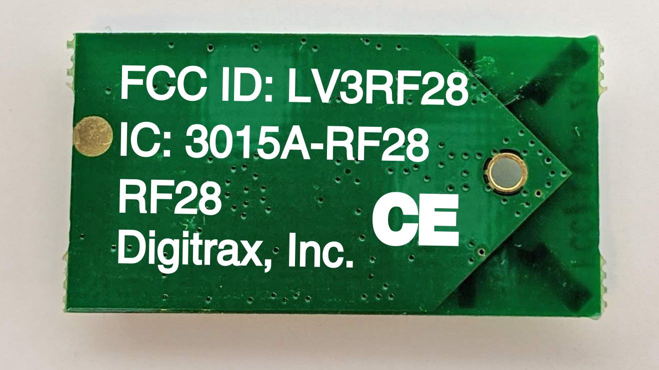
LV3RF28Zigbee Transceiver Module
Digitrax Inc
Click to zoom
Application Details
- Equipment Class
- DTS - Digital Transmission System
- Date of Grant
- Mar 27, 2020
- Application Purpose
- Original Equipment
- Date of Application
- Mar 26, 2020
- Equipment Note
- Zigbee Transceiver Module
- Frequency Range
- 2405.00000000 - 2475.00000000
- Company
- Digitrax Inc
- Country
- United States
Documents & Files
Document Text
Text extracted from the exhibit documents filed with the FCC. Open a document above to read the original.
Users Manual
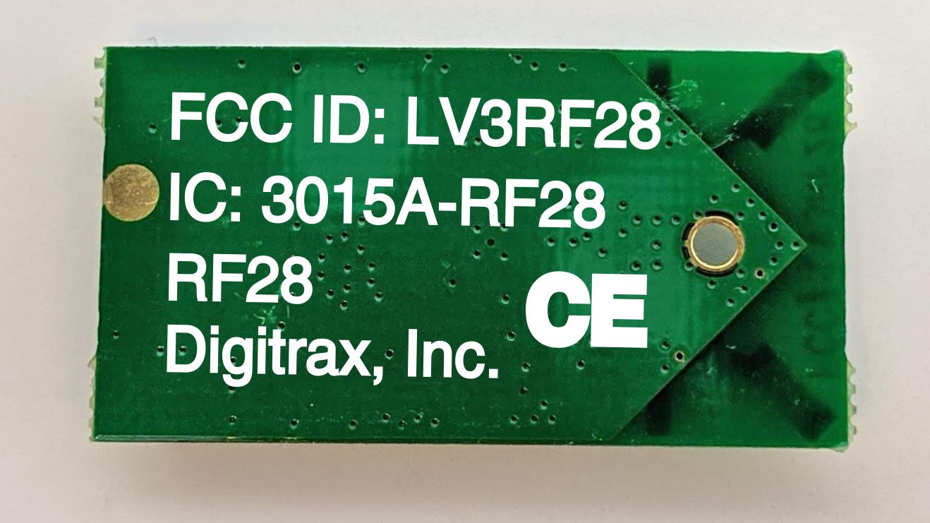
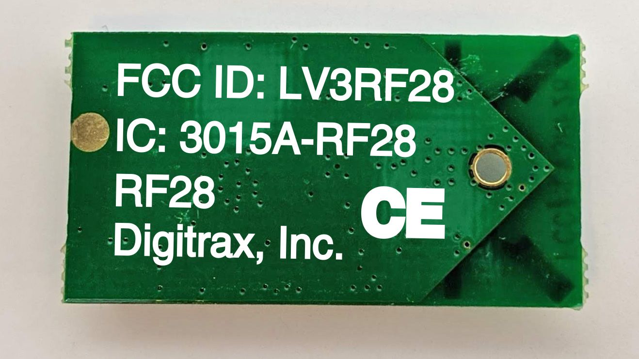
Digitrax RF28 Integration Manual:October 21, 2019 The RF28 RF module embodies an Atmel/Microchip Inc. AT86RF233 Zigbee/IEEE 802.15.4 type Transceiver MMIC, with a 12pin connector module plug-in digital control interface. The Host control driver firmware is configured for 47CFR15.212 Modular Transmitter Certification, and RF operations in the Band 2.405 to 2.480 GHz under 47CFR Part15.247, and is provided by Digitrax Inc. Panama City FL. Transmit power levels are configured to meet 15.247,15.205 and 15.209 frequency and emission limits, and in operation these may not exceed those measured in the FCC Report submission for 47CFR15.212 Modular Transmitter Certification. The RF28 employs two orthgonal integral Surface Mounted Space-Diversity sequential transmit/receive ceramic-chip Johanson 2450AT18B100E antennas. These are typically 0dBi gain, are fixed by the RF28 module OEM manufacturer, and are not user or integrator modifiable. This configuration inherently meets the antenna requirements of 15.203. There are no post-manufacturing modifiable or serviceable parts in the RF28. The RF28 modules measure 30x18x3mm maximum external dimensions and are identified with the indelible marking: “FCC#: LV3RF28” on the component side of the SMT module assembly. Due to limited space, the Regulatory information requirements are included below, and must be included in the final product manual. The RF28 is tested for 15.212 certification external to a Digitrax UR93 Host controller that is configured for the generation of the test signals and modes required for certification testing. Switches on the UR93 allow test lab step-changing of; channel, modulation rate and TX/RX modes as required, and visible on test equipment. This FCC testing portion of host firmware driver is not used or enabled in normal operation of the UR93 host unit, but the channel and power levels remain in effect as for certification requirements and final product operations. Integration of this RF28 47CFR15.212 Modular Certified Transmitter into a final Host product mandates that this final product then be tested as properly conforming to FCC requirements. RF exposure in the final product meets the requirements stated below. Regulatory Information: (must be included in final Host product manual) FCC: Contains FCC Module ID: LV3RF28 Declaration of Conformity: “This device complies with part 15 of the FCC Rules. Operation is subject to the following two conditions: (1) This device may not cause harmful interference, and (2) this device must accept any interference received, including interference that may cause undesired operation.” “This equipment has been tested and found to comply with the limits for a Class B digital device, pursuant to Part 15 of the FCC Rules. These limits are designed to provide reasonable protection against harmful interference in a residential installation. This equipment generates uses and can radiate radio frequency energy and, if not installed and used in accordance with the instructions, may cause harmful interference to radio communications. However, there is no guarantee that interference will not occur in a particular installation. If this equipment does cause harmful interference to radio or television reception, which can be determined by turning the equipment off and on, the user is encouraged to try to correct the interference by one of the following measures: Reorient or relocate the receiving antenna. Increase the separation between the equipment and receiver. Connect the equipment into an outlet on a circuit different from that to which the receiver is connected. Consult the dealer or an experienced radio/TV technician for help.” OEM RF28 Manufacturer/Responsible Party: Digitrax Inc., 2443 transmitter Rd, Panama City, FL 32404, USA. (850) 872 9890 Model: RF28 “Changes or modifications not expressly approved by Digitrax Inc., the party responsible for original RF28 Certification compliance under 47 CFR15.212, could void the user's authority to operate the equipment” Canada ISED RSS: Contains Canadian ID module: IC:3015A-RF28 This device complies with Industry Canada’s licence-exempt RSS's. Operation is subject to the following two conditions: (1) This device may not cause interference; and (2) This device must accept any interference, including interference that may cause undesired operation of the device.” “Le présent appareil est conforme aux CNR d’Industrie Canada applicables aux appareils radio exempts de licence. L’exploitation est autorisée aux deux conditions suivantes : 1) l’appareil ne doit pas produire de brouillage; 2) l’appareil doit accepter tout brouillage radioélectrique subi, même si le brouillage est susceptible d’en compromettre le fonctionnement.” RF28 RF Exposure Guidance: “In order to comply with FCC / ISED RF Exposure requirements, this device must be installed to provide at least 20 cm separation from the human body at all times.” “Afin de se conformer aux exigences d'exposition RF FCC / ISED, cet appareil doit être installé pour fournir au moins 20 cm de séparation du corps humain en tout temps.“
Cover Letter(s)
Digitrax Inc, 2443 Transmitter Rd., Panama City, FL 32404, USA. October 21, 2019 TUV SUD America Inc. 10 Centennial Drive Peabody, MA 01960, USA Dear Sir or Madam, We, Digitrax Inc, 2443 Transmitter Rd, Panama City, FL 32404 hereby authorize Marlene Sealey of TUV SUD America, 10040 Mesa Rim Road, San Diego, CA, 92121 to act as our agent in all matters relating to applications for equipment authorization, including the signing of all documents relating to these matters. Yours sincerely, Name:AJ Ireland Digitrax Inc. Title: Product Engineering
Cover Letter(s)
Digitrax Inc, 2443 Transmitter Rd, Panama City, FL 32404, USA October 21, 2019 Federal Communications Commission Equipment Authorization Branch 7435 Oakland Mills Road Columbia, MD 21046 Confidentiality Request FCC ID: LV3RF28 Pursuant to Sections 0.457(d)(1)(ii) and 0.459 of the Commission’s Rules, Digitrax Inc. hereby requests permanent confidential treatment of information accompanying this application as outlined below: Schematics Block Diagrams Theory of Operation Digitrax Inc. also hereby requests short-term confidential treatment of information accompanying this application as outlined below for a period of period of 120 days: Internal Photos External Photos User Manual Test Set-up Photographs The above materials contain trade secrets and proprietary information not customarily released to the public. The public disclosure of these matters might be harmful to the Applicant and provide unjustified benefits to its competitors. The Applicant understands that pursuant to Rule 0.457(d)(1)(ii), disclosure of this Application and all accompanying materials will not be made before the date of the Grant for this Application. Yours sincerely, Name: AJ Ireland Title: Product Engineering Company: Digitrax Inc.
Cover Letter(s)
Digitrax Inc 2443 Transmitter Rd Panama City FL 32404 October 21st 2019 Federal Communications Commission Equipment Authorization Branch 7435 Oakland Mills Road Columbia, MD 21046 Modular Approval Request FCC ID: LV3RF28 The following attestation addresses the requirements to support modular approval: Modular approval requirement Yes (provide brief statement)No * (a) The radio elements must have the radio frequency circuitry shielded. Physical components and tuning capacitor(s) may be located external to the shield, but must be on the module assembly YES. RF shield soldered over SMT active components (b) The module must have buffered modulation/data inputs to ensure that the device will comply with Part 15 requirements with any type of input signal YES. All inputs are buffered digital input lines (c) The module must contain power supply regulation on the module YES. Included 1% local LDO regulator (d) The module must contain a permanently attached antenna, or contain a unique antenna connector, and be marketed and operated only with specific antenna(s), per Sections 15.203, 15.204(b), 15.204(c), 15.212(a), 2.929(b) YES. Antennas are internal SMT and permanent. No additional power amplification. (e) The module must demonstrate compliance in a stand-alone configuration YES, driven externally to a UR93 Host (f) The module must be labelled with its permanently affixed FCC ID label, or use an electronic display (See KDB Publication 784748 about labelling requirements) YES. Module FCC ID permanently affixed to SMT side of module, visible near antennas (g) The module must comply with all specific rules applicable to the transmitter. The grantee must provide comprehensive instructions to explain compliance requirements YES. In User manual (h) The module must comply with RF exposure requirements YES * Please provide a detailed explanation if the answer is “No.” Yours sincerely, Name: AJ Ireland Title: Product Engineering Company: Digitrax Inc.
Internal Photos
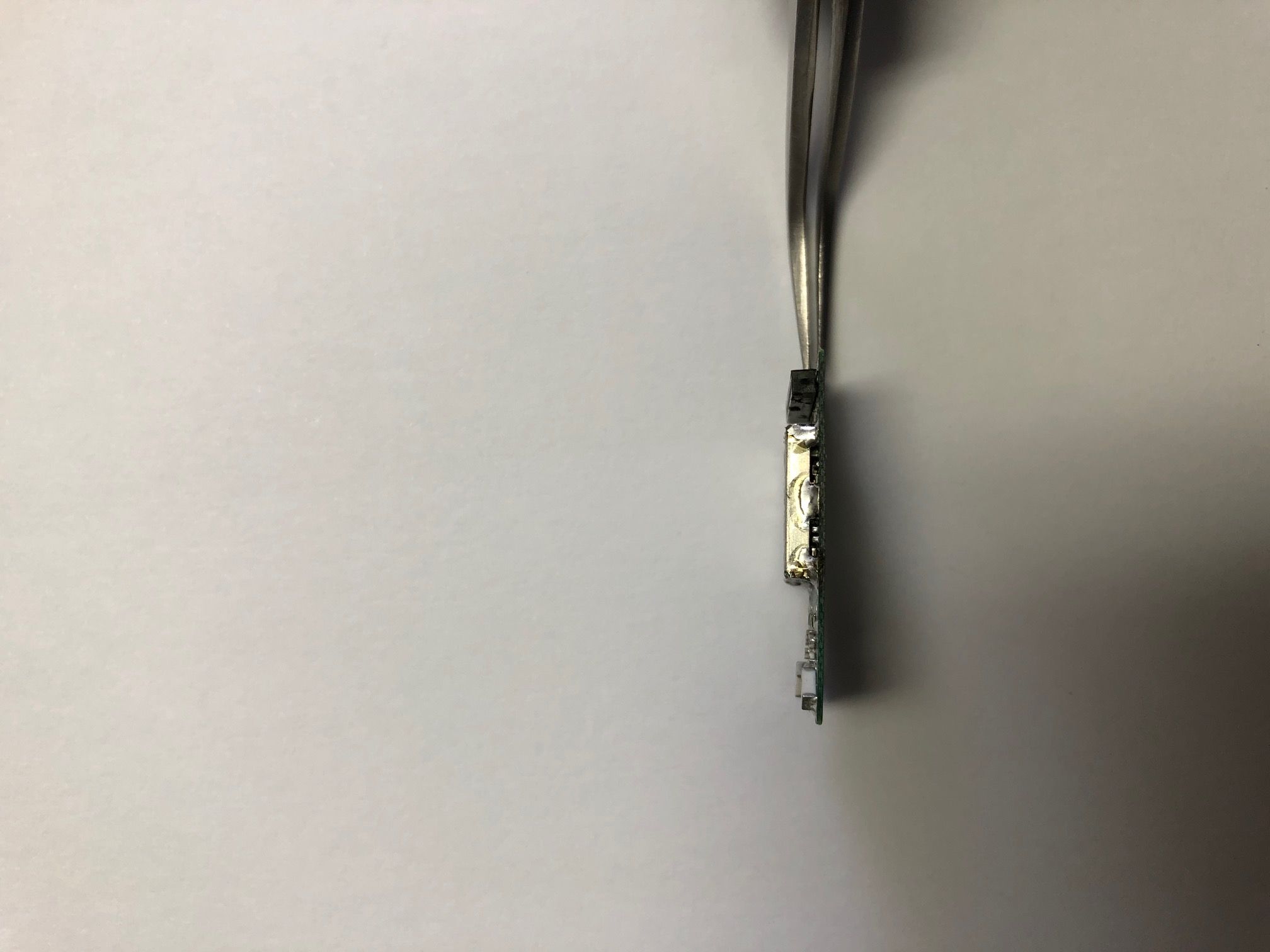
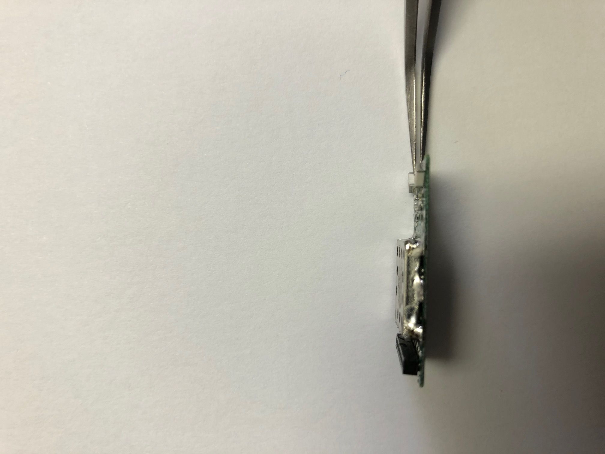
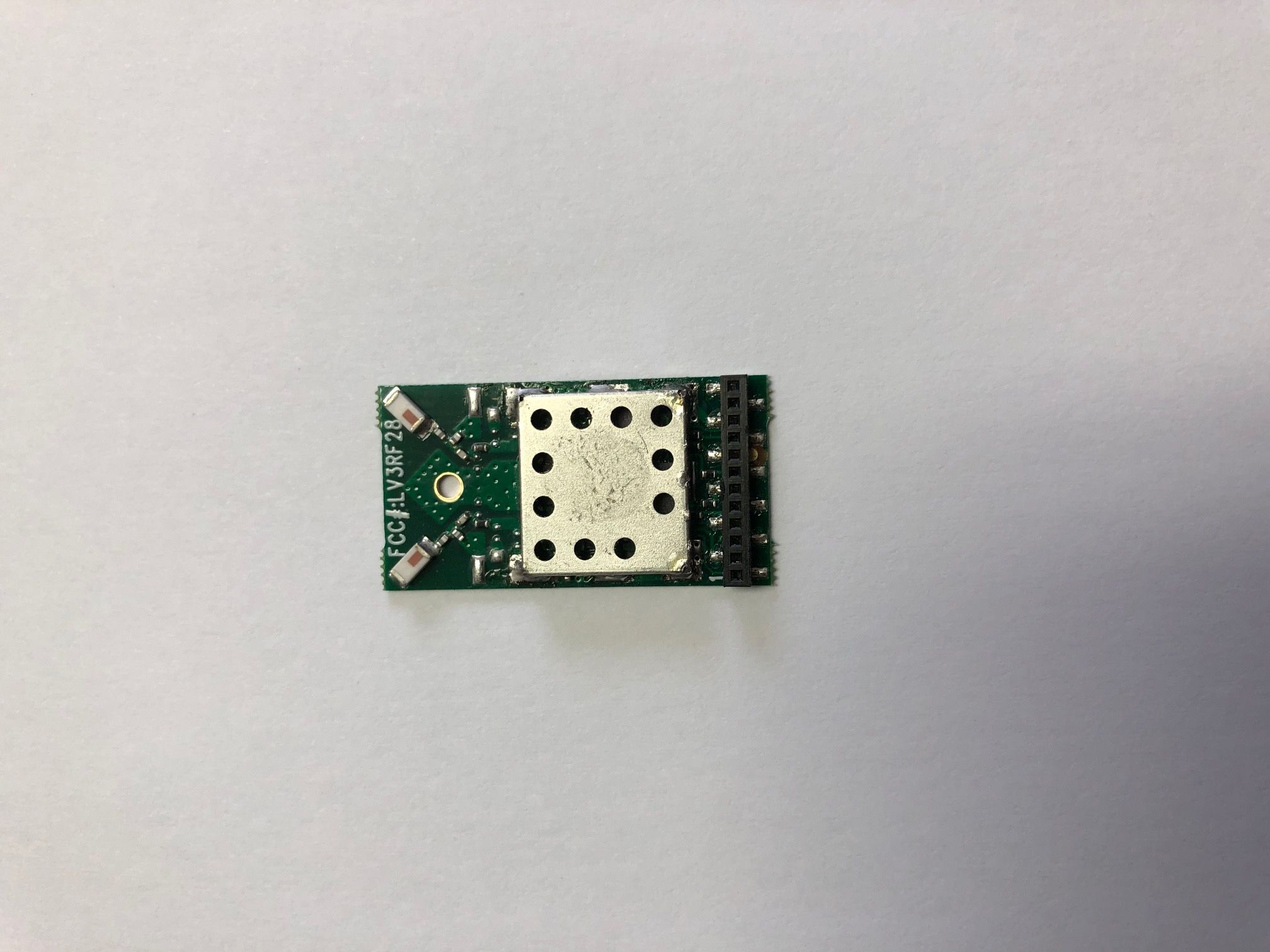
Antennas LDO regulator Antenna Matching parts AT86RF233 Transceiver RFX2411 PA/LNA 16MHz crystal 12 pin socket for digital control lines and power FCC ID marking Digitrax RF28 Top view part locations: LV3RF28
RF Exposure Info
5945 Cabot Parkway Suite 100 Alpharetta, GA 30005 USA Certification Exhibit FCC ID: LV3RF28 FCC Rule Part: 47 CFR Part 2.1091 Project Number: 72152852 Manufacturer: Digitrax, Inc. Model: RF28 RF Exposure Model(s): RF28FCC ID: LV3RF28 Report: AT72152852-2C0Page 2 General Information: Applicant: Digitrax, Inc. Device Category: Mobile Environment: General Population/Uncontrolled Exposure Technical Information: Antenna Type: Surface Mount Ceramic Chip Antenna Gains: Surface Mount Ceramic Chip / 0.5 dBi (Johanson Technology, P/N: 2450AT18B100) Maximum Transmitter Conducted Power: 19.3dBm, 85.11mW Maximum System EIRP: 19.8dBm, 95.50mW Exposure Conditions: Greater than 20 centimeters MPE Calculation The Power Density (mW/cm 2 ) is calculated as follows: S = 2 4R PG π Where: S = power density (in appropriate units, e.g. mW/cm2) P = power input to the antenna (in appropriate units, e.g., mW) G = power gain of the antenna in the direction of interest relative to an isotropic radiator R = distance to the center of radiation of the antenna (appropriate units, e.g., cm) Table 1: MPE Calculation Transmit Frequency (MHz) Radio Power (dBm) Power Density Limit (mW/cm 2 ) Radio Power (mW) Antenna Gain (dBi) Antenna Gain (mW eq.) Distance (cm) Power Density (mW/cm 2 ) 2405 19.3 1.00 85.11 0.5 1.122 20 0.019 Note: The device does not support simultaneous transmissions
Test Report
5945 Cabot Pkwy, Suite 100, Alpharetta, GA 30005 Test Report FCC ID: LV3RF28 IC: 3015A-RF28 FCC Rule Part: 15.247 ISED Canada Radio Standards Specification: RSS-247 Report Number: AT72152582-1C0 Manufacturer: Digitrax, Inc. Model: RF28 Test Begin Date: October 1, 2019 Test End Date: January 13, 2020 Report Issue Date: February 26, 2020 FOR THE SCOPE OF ACCREDITATION UNDER Certificate Number: 2955.09 This report must not be used by the client to claim product certification, approval, or endorsement by A2LA, NIST, or any agency of the Federal Government. Prepared By:Reviewed by: Ryan McGannKirby Munroe Senior Wireless EngineerTechnical Manager, US Wireless TÜV SÜD America Inc.TÜV SÜD America Inc. This test report shall not be reproduced except in full. This report may be reproduced in part with prior written consent of TÜV SÜD America Inc. The results contained in this report are representative of the sample(s) submitted for evaluation. This report contains 27 pages 5945 Cabot Pkwy, Suite 100, Alpharetta, GA 30005 TABLE OF CONTENTS 1GENERAL ...................................................................................................................................... 3 1.1PURPOSE ....................................................................................................................................... 3 1.2APPLICANT INFORMATION ............................................................................................................ 3 1.3PRODUCT DESCRIPTION ................................................................................................................ 3 1.4TEST METHODOLOGY AND CONSIDERATIONS ............................................................................... 3 2TEST FACILITIES ....................................................................................................................... 4 2.1LOCATION ..................................................................................................................................... 4 2.2LABORATORY ACCREDITATIONS/RECOGNITIONS/CERTIFICATIONS .............................................. 4 2.3RADIATED EMISSIONS TEST SITE DESCRIPTION ............................................................................ 5 2.3.1Semi-Anechoic Chamber Test Site – Chamber A ..................................................................... 5 2.3.2Semi-Anechoic Chamber Test Site – Chamber B ..................................................................... 6 2.4CONDUCTED EMISSIONS TEST SITE DESCRIPTION ......................................................................... 7 2.4.1Conducted Emissions Test Site ................................................................................................. 7 3APPLICABLE STANDARD REFERENCES ............................................................................. 8 4LIST OF TEST EQUIPMENT ..................................................................................................... 8 5SUPPORT EQUIPMENT.............................................................................................................. 9 6EQUIPMENT UNDER TEST SETUP BLOCK DIAGRAM ..................................................... 9 7SUMMARY OF TESTS................................................................................................................10 7.1ANTENNA REQUIREMENT –FCC15.203 ......................................................................................10 7.2POWER LINE CONDUCTED EMISSIONS –FCC15.207,ISEDCANADA:RSS-GEN 8.8 ..................10 7.2.1Measurement Procedure .........................................................................................................10 7.2.2Measurement Results ..............................................................................................................10 7.36DB/99%BANDWIDTH –FCC15.247(A)(2),ISEDCANADA:RSS-2475.2(A),RSS-GEN6.7 ..12 7.3.1Measurement Procedure .........................................................................................................12 7.3.2Measurement Results ..............................................................................................................12 7.4FUNDAMENTAL EMISSION OUTPUT POWER –FCC15.247(B)(3),ISEDCANADA:RSS-2475.4(D) .....................................................................................................................................................15 7.4.1Measurement Procedure .........................................................................................................15 7.4.2Measurement Results ..............................................................................................................15 7.5EMISSION LEVELS ........................................................................................................................16 7.5.1Emissions into Non-restricted Frequency Bands – FCC 15.247(d); ISED Canada: RSS-247 5.5 ............................................................................................................................................16 7.5.2Emissions into Restricted Frequency Bands – FCC: 15.205, 15.209; ISED Canada: RSS-Gen 8.9 / 8.10..................................................................................................................................18 7.5.3Sample Calculation: ................................................................................................................19 7.6MAXIMUM POWER SPECTRAL DENSITY IN THE FUNDAMENTAL EMISSION –FCC15.247(E)ISED CANADA:RSS-2475.2(B) ............................................................................................................20 7.6.1Measurement Procedure .........................................................................................................20 7.6.2Measurement Results ..............................................................................................................20 8ESTIMATION OF MEASUREMENT UNCERTAINTY .................................…
Text truncated - open the document above for the full version.
Test Setup Photos
5945 Cabot Parkway Suite 100 Alpharetta, GA 30005 USA Certification Exhibit FCC ID: LV3RF28 IC: 3015A-RF28 FCC Rule Part: 15.247 ISED Canada Radio Standards Specification: RSS-247 Project Number: 72152852 Manufacturer: Digitrax, Inc. Model: RF28 Test Setup Photos Model(s): RF28FCC ID: LV3RF28IC: 3015A-RF28 Project: 72152852Page 2 Figure 1: Equipment Under Test – Antenna Port Conducted Measurements Model(s): RF28FCC ID: LV3RF28IC: 3015A-RF28 Project: 72152852Page 3 Figure 2: Equipment Under Test – Radiated Emissions XPOS Model(s): RF28FCC ID: LV3RF28IC: 3015A-RF28 Project: 72152852Page 4 Figure 3: Equipment Under Test – Radiated Emissions YPOS Model(s): RF28FCC ID: LV3RF28IC: 3015A-RF28 Project: 72152852Page 5 Figure 4: Equipment Under Test – Radiated Emissions ZPOS Model(s): RF28FCC ID: LV3RF28IC: 3015A-RF28 Project: 72152852Page 6 Figure 5: Equipment Under Test – Radiated Emissions <30MHz Figure 6: Equipment Under Test – Radiated Emissions <1GHz Model(s): RF28FCC ID: LV3RF28IC: 3015A-RF28 Project: 72152852Page 7 Figure 7: Equipment Under Test – Radiated Emissions <1GHz Figure 8: Equipment Under Test – Radiated Emissions >1GHz Model(s): RF28FCC ID: LV3RF28IC: 3015A-RF28 Project: 72152852Page 8 Figure 9: Equipment Under Test – Radiated Emissions >1GHz Figure 10: Equipment Under Test – Radiated Emissions >18GHz Model(s): RF28FCC ID: LV3RF28IC: 3015A-RF28 Project: 72152852Page 9 Figure 11: Equipment Under Test – Radiated Emissions >18GHz Figure 12: Equipment Under Test – AC Conducted Emissions Model(s): RF28FCC ID: LV3RF28IC: 3015A-RF28 Project: 72152852Page 10 Figure 13: Equipment Under Test – AC Conducted Emissions
Contact Information
Applicant
AJ Ireland(VP Engineering/Company secretary)
[email protected]850-872-9890
Test Firm
TUV SUD America, Inc.William Elliott
[email protected]813-284-2736
Technical Specifications
| # | Rule Parts | Frequency Range | Power Output |
|---|---|---|---|
| 1 | 15C | 2.40 GHz - 2.48 GHz | 85.11 mW |
Other Applications from Digitrax Inc
LV3RF24
Aug 07, 2007RF24 RADIO TRANSCEIVER MODULE
Equipment Class
DXX - Part 15 Low Power Communication Device Transmitter
LV3RF1
Sep 27, 2000Transmitter Module for Digitrax Products
Equipment Class
DXX - Part 15 Low Power Communication Device TransmitterLV3DT100R
Mar 15, 1998Model Locomotive Control Transmitter
Equipment Class
DXX - Part 15 Low Power Communication Device TransmitterLV3MS100PR1-A
May 16, 1995Model Railroad Controller
Equipment Class
JBP - Part 15 Class B Computing Device Peripheral