LWNF21-E1Transmitter
Lee's High-Tech Enterprise Co Ltd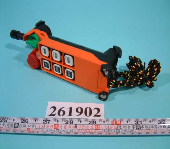
Click to zoom
Application Details
- Equipment Class
- DSC - Part 15 Security/Remote Control Transmitter
- Date of Grant
- Sep 24, 2002
- Application Purpose
- Original Equipment
- Date of Application
- Sep 24, 2002
- Equipment Note
- Transmitter
- Frequency Range
- 310.00000000 - 320.00000000
- Country
- Taiwan
Documents & Files
Document Text
Text extracted from the exhibit documents filed with the FCC. Open a document above to read the original.
Users Manual
Installation & Operation Manual FCC ID: LWNF21-E1 F21-E1 type Industrial Radio Remote Controller TELECRANE Lee’s Hi-tech Ent. Co., Ltd. 6/14/2002 Table Of Contents Part. 1 Operator’s Manual Chapter 1 Warranty Chapter 2 Precautions Of Operation Chapter 3 F21-E1 Standard Accessories Chapter 4 Operation Chapter 5 Troubleshooting and Software Installation 1 Safety Considerations This product and related documentation must be reviewed for familiarization with safety markings and instructions before operation. Safety Symbols The following symbols may be found on the remote control or throughout the remote control’s documentation. Refer to Manual When product is marked with this symbol refer to instruction manual for additional information. High Voltage Indicates presence of hazardous voltage. Unsafe practice Could result in severe personal injury. Protective Earth Ground Indicates protective earth terminal. Warning Denotes a hazard. Included text gives proper procedures. Failure to follow instructions could result in severe personal injury and/or property damage. Caution Denotes a hazard. Included text gives proper procedures. Failure to follow instructions could result in minor personal injury and/or properly damage. 2 Part 1. Operator’s Manual Chapter 1 Warranty 1-1 Warranty Lee’s Hi-Tech Enterprises Co., Ltd. guarantees that this product meets its published specifications at the time of shipment from the factory. Under proper installation it should work as expected. 1-2 Warranty Period This equipment is warranted against defects in material and manufacturing for a period of one year from the date of shipment. During the warranty period, TELECRANE is responsible for necessary repairs as long as the product can be proved to be defective. For warranty service or repair this product must be returned to a service facility designated by TELECRANE. Buyer will pay shipping charges to TELECRANE while TELECRANE will pay return shipping charges. 1-3 Excluded Items This warranty does not include consumptive parts such as batteries, fuses, buttons, relays. Also this warranty does not cover defects caused by improper installation, improper or insufficient maintenance, unauthorized modification, improper operation, ignorance of environmental specifications, or improper software or interfacing. 1-4 Remarks No other warranty is expressed or implied, except for the above mentioned. The remedies provided herein are the buyer’s sole and exclusive remedies. TELECRANE shall not be liable for any direct, indirect, special, incidental or Consequential damages. 3 Chapter 2 Precautions of Operation 2-1 Attention Please carefully read the manual before installing and operating this device. Due to the complex nature of this equipment it is necessary to read the entire manual before installation. Never dismantle the equipment by any unauthorized personnel, or equipment may be damaged. This manual is for reference only. Pleases consult your distributor for further assistance. The equipment has been strictly tested for quality before delivery from our plant. However, this equipment must not be used in dangerous situations or where damage may result. After finishing operation of TELECRANE shut off main power to the crane, power to receiver, and remove transmitter key. If transmitter’s power is controlled by “rotary key switch”, then need turn the key to “OFF” position and remove it. Transmitter should be placed in a safe area when not in use to avoid accidental pressing of buttons. The crane should be equipped with main power relay, limit switch and other safety devices. The GND (ground) of the receiver must be in contact with the metal part of the crane or electrical shock may occur. Don’t use equipment during lightening or high electrical interference conditions. Make sure that the batteries are in good condition and power for receiver is correct. Installation and maintenance should only be done while the crane’s main power is off to prevent electrical shock. The contents of this manual may be amended by the manufacturer without notice. The manufacturer may introduce new functions to the equipment as necessary, therefore, the descriptions may change. The patent and related documents for the equipment belong to LEE’S HI-TECH CO., LTD. and they aren’t allowed to be used by others without permission. F21 series systems adopt many of patents belong to LEE’S HI-TECH CO., LTD. and its associated companies. 4 2-2 Precautions Operating in an industrial facility is highly dangerous, therefore, operator must have adequate training in using TELECRANE with this in mind. Those who operate the machine should be healthy and have good judgment in regards to safety. Although the F21 transmitter is very durable and weather resistant care should be taken not to expose it to severe impact or pressure. During operation, if the power supplied from transmitter’s batteries is insufficient, the transmitter will send out EMS signal first to de-energize all of motion relays inside the receiver to stop crane’s moving (Notice: the motions which are set as ”Bypass EMS” will continuously move.), and then the LED indicator on transmitter will light continuously. At this time, need to be replaced with AA size alkaline batteries. All batteries should be replaced at the same time. Don’t use manganese-zinc batteries because of their corrosive properties. If the severe interference occurred you should stop using the equipment at once. Please take the battery out when the equipment will not be used for a long time. Be sure to know the “Procedures of emergency” in case of emergency. 5 2-3 Procedures of emergency The F21 system has various protections to guard against different emergencies including strict security code checking and automatic monitoring of parts failure. The F21 system has isolation circuitry to protect from outside voltage surges and interference. In the event of sensing an emergency situation the F21 will perform an emergency stop of the eq…
Text truncated - open the document above for the full version.
External Photos
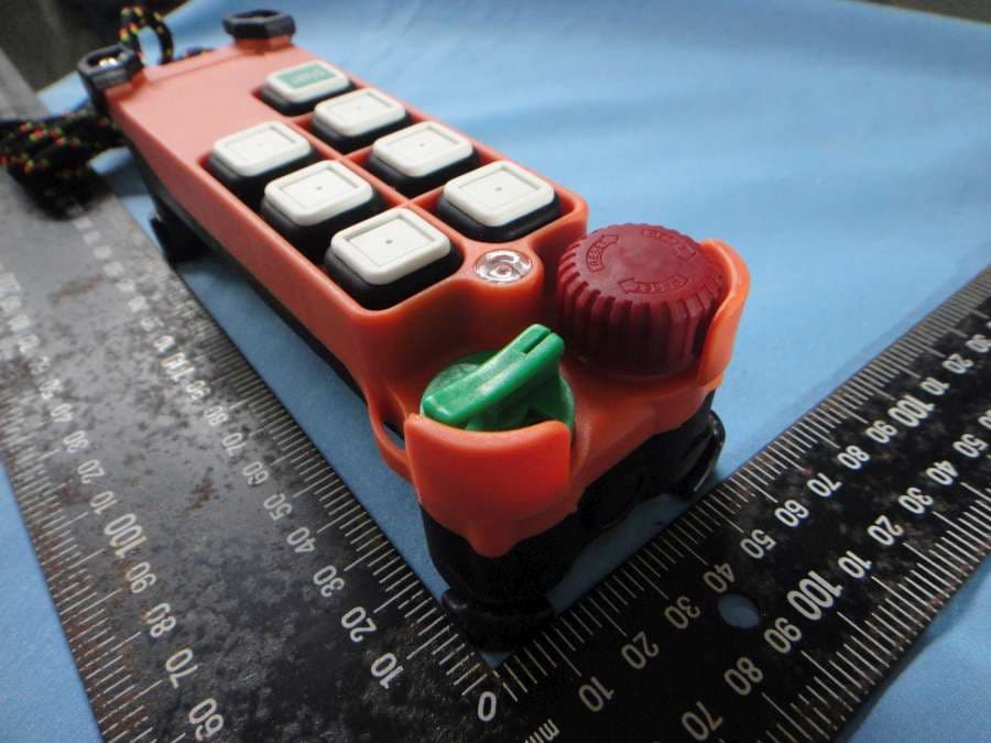
FCC ID :LWNF21-E1 FRONT S I DE OF E U T Num b er 1 REAR SI DE O F EU T Num b er 2 FCC ID : LWNF21-E1
ID Label/Location Info
FCC ID Label Drawing FCC ID:LWNF21-E1 The following statement will be placed in the User’s Manual. This device complies with Part 15 of the FCC Rules. Operation is subject to the following two conditions: (1) this device may not cause harmful interference, and (2) this device must accept any interference received, including interference that may cause undesired operation.
ID Label/Location Info
FCC ID : L W NF2 1-E1 FCC ID LOCA TIO N
Internal Photos
FCC ID : LWNF21-E1 N u m b e r 1 M e c h an ic al Con s t r uc t i on FCC ID : LWNF21-E1 N u m b e r 2 M e c h an ic al Con s t r uc t i on FCC ID : LWNF21-E1 N u m b e r 3 F r o n t SI DE O F Ma in bo a r d FCC ID : LWNF21-E1 N u m b e r 4 REAR SI DE O F Ma in bo a r d FCC ID : LWNF21-E1 N u m b e r 5 F r o n t SI DE O F Mo d u le bo a r d FCC ID : LWNF21-E1 N u m b e r 6 REAR SI DE O F Mo d u le bo a r d
Operational Description
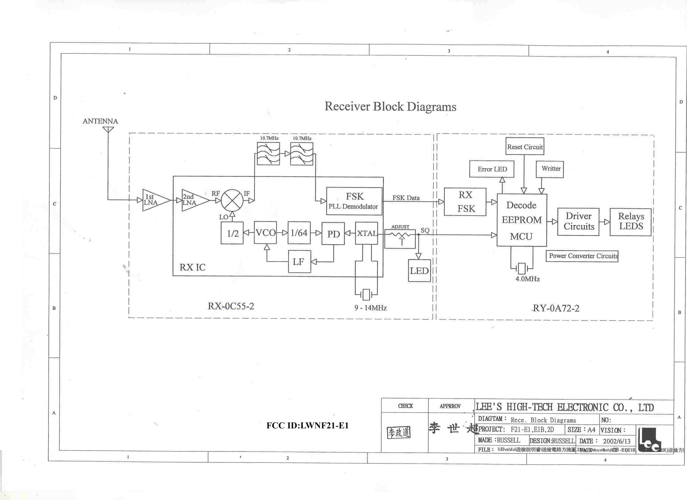
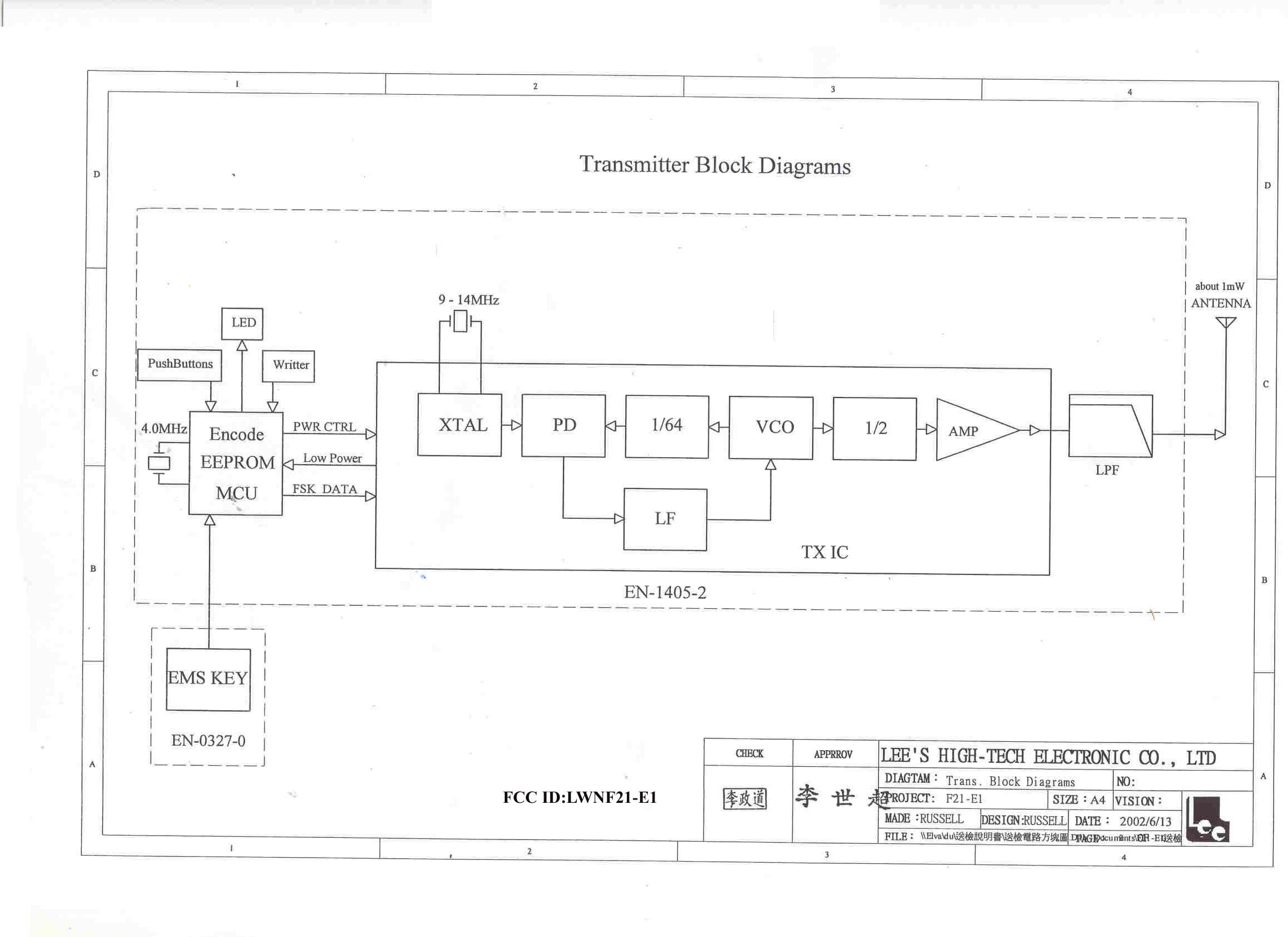
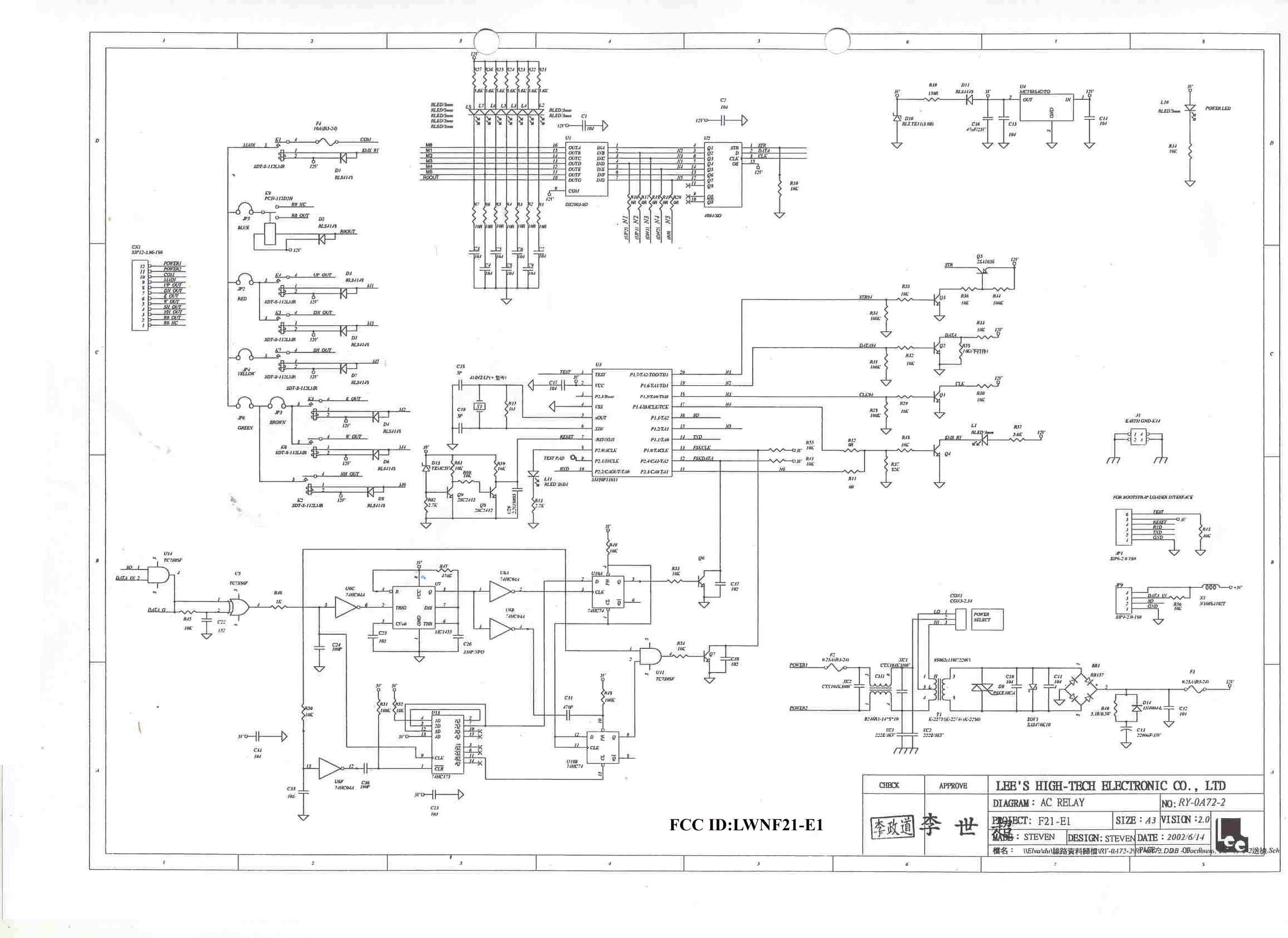
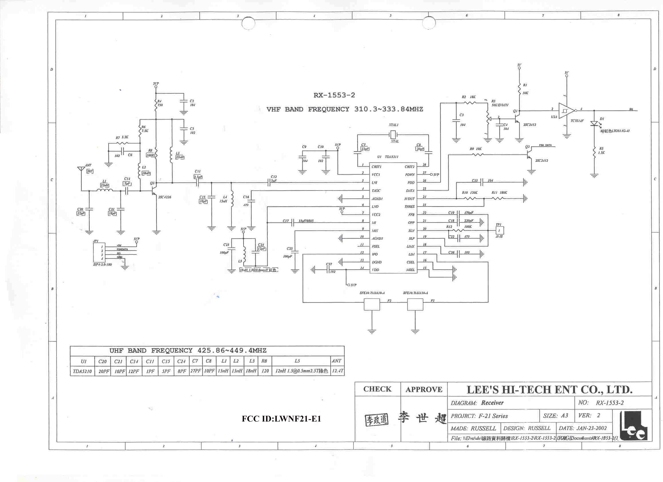
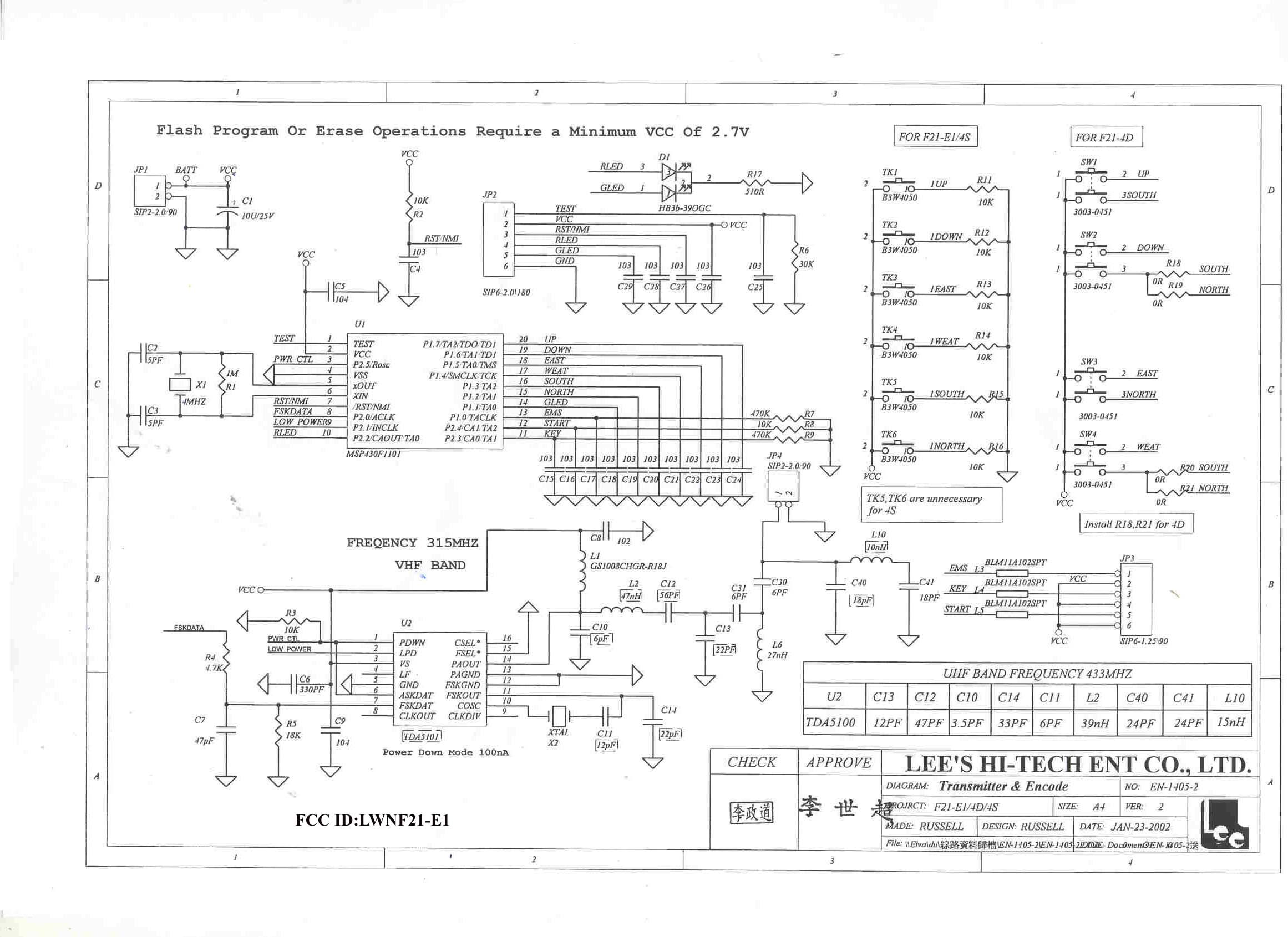
FCC ID: LWNF21-E1 Chapter 6 Basic Operational Principle of Remote Controller 1. General The basic operational principle of Radio Remote Controller utilizes a radio transmitter to transmit the control data, and a receiver to receive the control data from transmitter, decode the data, and generate control commands to control the motions of a crane (or other mechanical devices). 2. Operational principle of Transmitter unit Connect with PC/COPIER 6-Pin socket E 2 PROM Pushbuttons and switches Keypad circuit Encoding circuit Micro control unit (MCU) Reference frequency generator circuit Frequency comparator circuit Low pass filter v.c.o. RF amplifier Feedback signal Low pass filter Antenna FSK DATA LED indicator Fig.1 Transmitter’s function block diagram The micro control unit (MCU) is the heart of the transmitter. Except the MCU, the transmitter consists of four peripheral circuits containing keypad circuit, encoding circuit, electrically erasable programmable read only memory (E 2 PROM) and TX-RF oscillating circuit. When press buttons or turn switches on the transmitter, the keypad circuit senses and sends the correct data to the encoding circuit then to the MCU, and combine with “function setting”, “ID codes” and “Hamming codes” become “control data” which will be swapped to TXFSK DATA via the encoding method of Manchester and send to TX-RF oscillating circuit. To control reference frequency generator with TXFSK DATA and generate a modulation signal which will modulate voltage control oscillator (V.C.O.) and output a frequency modulation signal. This FM signal goes through TX-RF amplifier, low pass filter and then TX’s antenna to generate a transmission signal. In addition to TX-RF amplifier, at the same time, Voltage control oscillator (V.C.O.) will feedback to phase comparator circuit become “Phase Rocked Hoop”. If temperature factor influence with V.C.O. and cause frequency shifting, then “Phase Rocked Hoop” will detect and generate a voltage control signal to control V.C.O. and calibrate its frequency shifting, and keep V.C.O. with a stable frequency output always. The main function of E 2 PROM is to store function settings, ID codes etc. It can do function setting, or read the detail data from E 2 PROM via 6-pin socket connecting with PC or Copier. 3. Operational principle of Receiver unit Command Data Low pass filter Low noise RF amplifier IF filter FM demodulator Low pass filter Crystal oscillator Phase comparator E2PROM Relays driver Relays output relays LED indicator Serial /parallel converter Micro control unit (MCU) RX FSK circuit Feedback signal 6-Pin socket Antenna mixer FSK DATA V. C . O Fig.2 Receiver’s function block diagram The receiver unit consists of RF amplifier circuit, frequency mixing circuit, decoding circuit and relays driving circuit. RF signal (control data) from the transmitter are received by the receiver’s antenna and go through low pass filter to filter noise , to amplify RF signal via “low noise RF amplifier” with characters of temperature compensation and high receiving gain, then send to mixer combining with local oscillator to generate IF signal. In order to obtain a stable IF signal, this system adopts “Phase Lock Loop” (PLL) and “Voltage Control Oscillator” (V.C.O.) to be a combined circuit as a local oscillator circuit. After demodulating, the IF signal output a low frequency of FSK DATA to RXFSK circuit which is used for detecting and correcting error to ensure the data sent to MCU is complete and correct. The MCU has control data and proofread ID codes, Hamming codes etc., according to function setting in E 2 PROM to generate corresponding control data to relays driving circuit. The control data from MCU is a serial/parallel transmission, so it shall go through “serial/parallel converter” and swap to respective control data sent to “relays driver” in order to conduct relays and the corresponding LED light.
Test Report
FCC TEST REPORT Report No. : F261902 SPORTON International Inc. TEL : 886-2-2696-2468 FAX : 886-2-2696-2255 FCC TEST REPORT for 47 CFR, Part 15, Subpart C Equipment : Industrial Radio Remote Controller Model No. : F21-E1 FCC ID : LWNF21-E1 Filing Type : Certification Applicant : Lee’s Hi-Tech Enterprise Co., Ltd. 8F-1, No. 288-2, Hsin Ya Rd., Chien Chen Zone, KaoHsiung, Taiwan, R.O.C. † The test result refers exclusively to the test presented test model / sample. † Without written approval of SPORTON International Inc., the test report shall not be reproduced except in full. † Certificate or Test Report must not be used by the applicant to claim the product in this test report endorsement by NVLAP or any agency of U.S. government. SPORTON International Inc. 6F, No.106, Sec. 1, Hsin Tai Wu Rd., Hsi Chih, Taipei Hsien, Taiwan, R.O.C. FCC TEST REPORT Report No. : F261902 SPORTON International Inc. FCC ID : LWNF21-E1 TEL : 886-2-2696-2468 Page No. : i FAX : 886-2-2696-2255 Issued Date : Aug. 6, 2002 Table of Contents History of this test report .............................................................................................................................................ii CERTIFICATE OF COMPLIANCE...................................................................................................................................................1 1. General Description of Equipment under Test..................................................................................................................2 1.1. Applicant.......................................................................................................................................................................................2 1.2. Manufacturer.................................................................................................................................................................................2 1.3. Basic Description of Equipment under Test...................................................................................................................................2 1.4. Feature of Equipment under Test..................................................................................................................................................2 2. Test Configuration of Equipment under Test.....................................................................................................................3 2.1. Test Manner..................................................................................................................................................................................3 2.2. Description of Test System...........................................................................................................................................................3 2.3. Connection Diagram of Test System.............................................................................................................................................4 2.4. A plot shows the EUT meet the requirement of 15.231(c).............................................................................................................5 3. Test Software.....................................................................................................................................................................................7 4. General Information of Test........................................................................................................................................................8 4.1. Test Facility...................................................................................................................................................................................8 4.2. Standard for Methods of Measurement.........................................................................................................................................8 4.3. Test in Compliance with................................................................................................................................................................8 4.4. Frequency Range Investigated......................................................................................................................................................8 4.5. Test Distance................................................................................................................................................................................8 5. Test of Conducted Powerline....................................................................................................................................................9 6. Test of Radiated Emission........................................................................................................................................................10 6.1. Major Measuring Instruments......................................................................................................................................................10 6.2. Test Procedures..........................................................................................................................................................................11 6.3. Typical Test Setup Layout of Radiated Emission........................................................................................................................12 6.4. Test Result of Radiated Emission...............................................................................................................................................13 7. Antenna Factor & Cable Loss..................................................................................................................................................25 8. EMI Suppression Component List.........................................................................................................................................26 9. List of Measuring Equ…
Text truncated - open the document above for the full version.
Test Setup Photos
FCC TEST REPORT Report No. : F261902 1.1. Photographs of Radiated Emission Test Configuration z The photographs show the configuration that generates the maximum emission. FRONT VIEW REAR VIEW SPORTON International Inc. FCC ID : TEL : 886-2-2696-2468 Page No. : 1 of 1 FAX : 886-2-2696-2255 Issued : Sep, 03, 2002
Contact Information
Applicant
Mr.Russell Lee(General Manager)
Test Firm
SPORTON International IncKathy Lin
Technical Specifications
| # | Rule Parts | Frequency Range | Power Output |
|---|---|---|---|
| 1 | 15.231 | 310 MHz - 320 MHz | - |
Other Applications from Lee's High-Tech Enterprise Co Ltd
LWN1211F53
Dec 25, 2012Industrial Radio Remote Controller
Equipment Class
DXX - Part 15 Low Power Communication Device Transmitter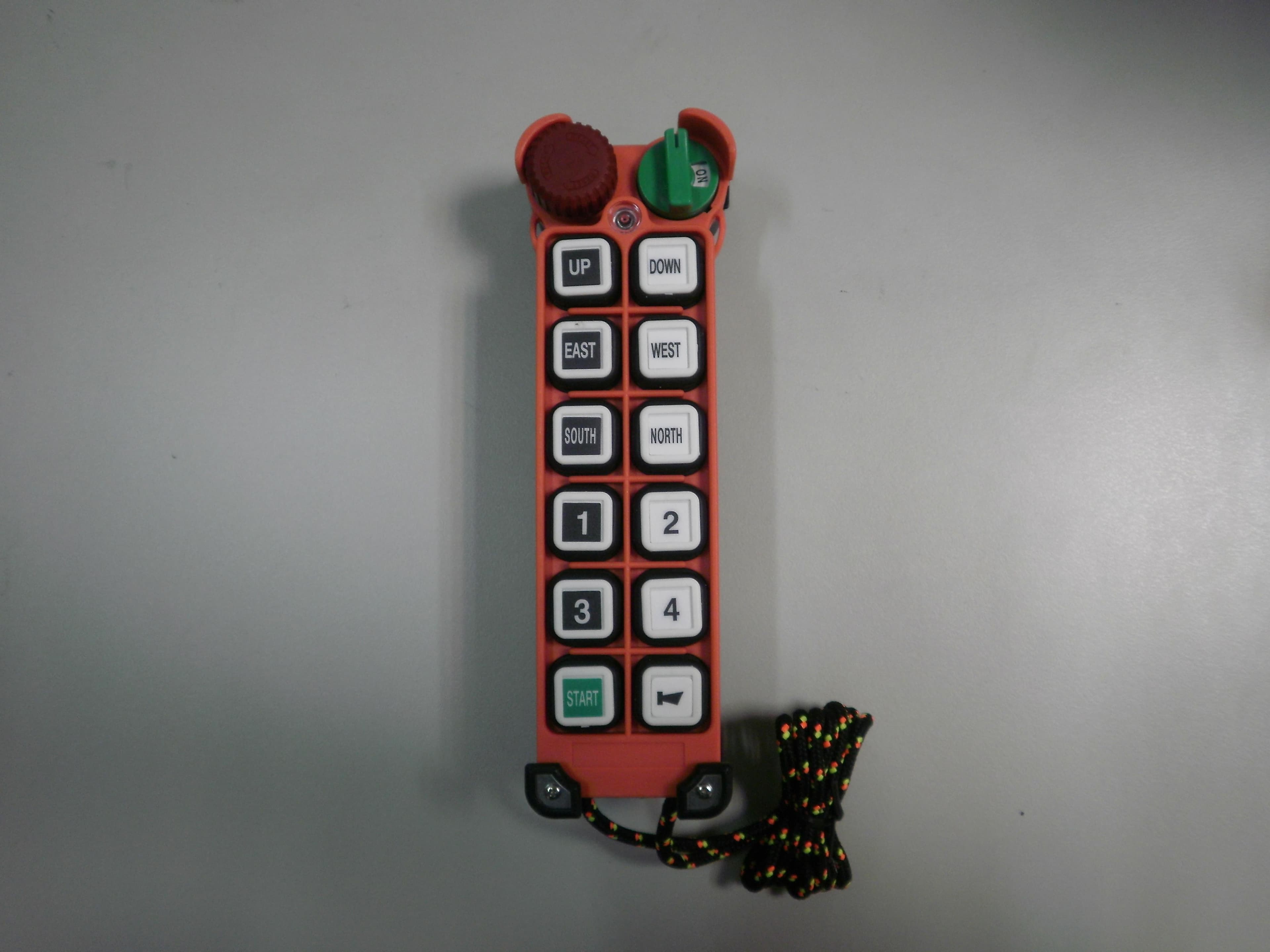
LWN1211F52
Dec 25, 2012Industrial Radio Remote Controller
Equipment Class
DXX - Part 15 Low Power Communication Device Transmitter
LWN1211F51
Dec 22, 2012Industrial Radio Remote Controller
Equipment Class
DXX - Part 15 Low Power Communication Device Transmitter
LWN1211FE2
Dec 16, 2012Industrial Radio Remote Controller
Equipment Class
DXX - Part 15 Low Power Communication Device Transmitter
LWN1211F60
Dec 15, 2012Industrial Radio Remote Controller
Equipment Class
DXX - Part 15 Low Power Communication Device Transmitter