LYIAT1251250W UHF ATSC Transmitter
Hitachi Kokusai Electric America LTD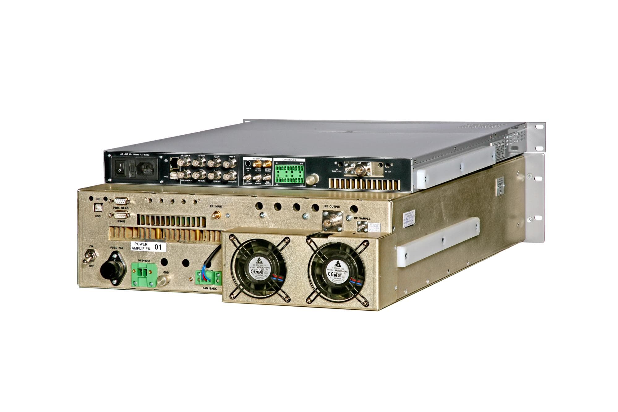
Click to zoom
Application Details
- Equipment Class
- TBC - Licensed Broadcast Station Transmitter
- Date of Grant
- Mar 18, 2013
- Application Purpose
- Original Equipment
- Date of Application
- Mar 18, 2013
- Equipment Note
- 250W UHF ATSC Transmitter
- Frequency Range
- 614.00000000 - 698.00000000
- Country
- United States
Documents & Files
Document Text
Text extracted from the exhibit documents filed with the FCC. Open a document above to read the original.
Users Manual
Linear Industries, Inc. AT71-250 Owner’s Manual February 2013 AT71-250 Transmitter Owner’s Manual © Linear Industries, Inc. All Rights Reserved 2/38 User Notices and WARNINGS USER NOTICES IT IS VERY IMPORTANT TO READ THIS MANUAL PRIOR TO OPERATION OF THIS TRANSMITTER! Notice 1 The transmitter main operating voltage setting is marked on the rear of the AT71-250 chassis. Notice 2 The transmitter operating frequency is set from the factory. Notice 3 For adjusting the RF output power setting a qualified technician should always employ the use of an RF Wattmeter and a calibrated dummy load. Notice 4 Should accident or injury occur to the personnel engaged in the installation, operation, or service of the equipment, they should seek proper medical attention. It is advisable that such personnel have familiarity with first-aid practices. Notice 5 For technical support please call the Linear technical support customer service line at 847/428-5793 ext. 105. Notice 6 The technical information presented on this manual is sole intellectual propriety of Linear Industries, Inc. Reproduction of this document in full or partial is prohibited without written authorization. This document is legally protected by the copyright laws. AT71-250 Transmitter Owner’s Manual © Linear Industries, Inc. All Rights Reserved 3/38 WARNING! THE VOLTAGES AND CURRENTS IN THIS EQUIPMENT ARE DANGEROUS. PERSONNEL MUST, AT ALL TIMES, OBSERVE SAFETY WARNINGS, INSTRUCTIONS, AND ANY LOCAL REGULATIONS. THIS OWNER’S MANUAL IS INTENDED AS A GENERAL GUIDE FOR TRAINED AND QUALIFIED PERSONNEL WHO ARE AWARE OF THE DANGERS THAT ARE INHERENT IN THE HANDLING AND OPERATION OF POTENTIALLY HAZARDOUS ELECTRICAL AND ELECTRONIC CIRCUITS. IT IS NOT THE INTENT OF THIS MANUAL TO PROVIDE A COMPLETE SET OF SAFETY INSTRUCTIONS OR PRECAUTIONS THAT SHOULD ALREADY BE UNDERSTOOD BY TRAINED OR EXPERIENCED PERSONNEL IN USING THIS OR OTHER TYPES AND FORMS OF ELECTRONIC EQUIPMENT. THE INSTALLATION, OPERATION, AND MAINTENANCE OF THIS EQUIPMENT INVOLVE RISKS TO PERSONNEL AND ALSO TO THE EQUIPMENT. LINEAR, INC. SHALL NOT BE RESPONSIBLE FOR INJURY OR DAMAGE THAT IS THE RESULT OF IMPROPER PROCEDURES OR USE BY INDIVIDUALS IMPROPERLY TRAINED OR LACKING THE KNOWLEDGE TO PERFORM ASSOCIATED TASKS. ALL LOCAL CODES FOR BUILDING, SAFETY, FIRE, OR RELATED STANDARDS MUST BE OBSERVED. CONSULT LOCAL AUTHORITIES FOR THE STANDARDS FOR THE AREA OR REGION WHERE THE EQUIPMENT WILL BE INSTALLED AND PUT IN USE. WARNING! AT ALL TIMES DISCONNECT AC/MAIN POWER BEFORE OPENING COVERS, DOORS, ENCLOSURES, PANELS, OR PROTECTIVE SHIELDS THAT EXPOSE LIVE CIRCUITS. NEVER PERFORM MAINTENANCE, MAKE ADJUSTMENTS, OR SERVICE THE EQUIPMENT WHEN ALONE OR FATIGUED. WARNING! IF ELECTROLYTIC OR OIL FILLED CAPACITORS ARE UTILIZED IN THE EQUIPMENT AND THE COMPONENT APPEARS LEAKY, OR IS BULGING, OR IF THE CASE OR COVERING OF THE COMPONENT APPEARS DAMAGED OR DISTRESSED, ALLOW SUFFICIENT TIME FOR THE UNIT TO COOL OR FULLY DISCHARGE BEFORE SERVICING. SERVICING HOT OR LEAKY CAPACITORS CAN CAUSE A RUPTURE OF THE CASE AND POSSIBLE INJURY. AT71-250 Transmitter Owner’s Manual © Linear Industries, Inc. All Rights Reserved 4/38 Returns and Exchanges Equipment (Damaged or undamaged) should not be returned unless written approval and a Merchandise Return Authorization (MRA Number) is received from your Linear Sales representative or Linear Customer Service. Special shipping instruction will be provided which will assure proper handling. The circumstances and reasons for the return must be included in the request for return. Equipment that is special or “custom” ordered may be not returnable. In situations where return or exchange is at the request of the customer a restocking fee may be charged. All returns must be sent freight prepaid and properly insured by customer. When communicating with Linear please refer to your Order or Invoice Number. Unpacking Use care when unpacking the equipment. First perform a visual inspection of the item(s) to determine if any damage occurred during shipment. Be sure to retain all the shipping materials (crates and boxes or cartons) until such time that it has been determined that the received equipment arrived undamaged. Find all PACKING LISTS and keep them to assist in locating and identifying any components or assemblies that may have been removed for shipping and might need to be reinstalled in the equipment. Make sure that all shipping straps, supports and packing materials are completely removed from the equipment prior to initialization and use. AT71-250 Transmitter Owner’s Manual © Linear Industries, Inc. All Rights Reserved 5/38 AT71-250 General Description 1. INTRODUCTION AT71-250 is a 250W UHF ATSC Digital Broadcast Transmitter. It uses state-of-the-art technology of transmission of the digital signal for TV broadcast. It carries an intelligent digital control using microcontrollers, which allows for remote supervision in real time of all transmitter functionality. All operations of the AT71-250 is carried-out through a keypad and digital display, located on the front panel, including access to all the readings, alarms and configurations. The RF amplification system constitutes one drawer of up to 300W rms comes with an independent power supply and supervision function. The FCC Mask filter is installed on the top of the cabinet (not shown on the pictures below). Figure 1: AT72-250 - Front View AT71-250 Transmitter Owner’s Manual © Linear Industries, Inc. All Rights Reserved 6/38 Figure 2: AT72-250 - Rear View Figure 3 - AT71-250 - Block Diagram AT71-250 Transmitter Owner’s Manual © Linear Industries, Inc. All Rights Reserved 7/38 2. Main Features Via the 4 lines x 40 columns display keypad located at the front panel it is possible to manage, configure all functions of the equipment and each one of the RF power drawer. Via the hyper-terminal it is also possible to manage, configure all of the functions of the transmitter. Digital Filter, type Finite Impulse Power (FIR) …
Text truncated - open the document above for the full version.
Cover Letter(s)
www.linear-tv.com Linear Industries, Inc. 2531 Technology Dr., Suite 310 ▲ Elgin, IL 60124 ▲ 847.428.5793 3/8/2013 FCC ID: LYIAT1251 Request for Confidentiality In accordance with 47 C.F.R. Section 0.459, we, Linear Industries, hereby request confidentiality for the block diagram, parts list, schematic and product description presented for certification. In support of the Request for Confidentiality, the following is stated: Enclosed within this application is technical information which we deem to be trade secrets and proprietary. If made public, the information might be used to our disadvantage. To assist in assuring that we receive the full value of our product and protect its competitive posture, we respectfully request this grant of confidentiality. Carlos Fructuoso Linear Equipamentos Eletronicos
External Photos
AT71-250 Front View AT71-250 Rear View
ID Label/Location Info
MODEL: AT71-250 3" 1" FCC ID:LYIAT1251 ORIGIN: USA LINEAR INDUSTRIES Inc. Label Location AT71-250
Internal Photos
Top View Exciter AT8001 Bottom View RF 250w Amplifier Top View RF 250w Amplifier
Schematics
Manual Rev. 0.0 – March 2012 Electrical Schematics MOD GV 4790 Annex (Power Drawer) Annex - Electrical Schematics MOD GV 4790 1-1 a) Power Source - CIM 3918A (CIP 8708A) .................................................... 1-7 b) Control Board of Power Supply 50V - CIM 3855B (CIP 8696) ................... 1-8 4. PFC 2kW Power Supply- Module 4810 ........................................................ a) Power Supply - CIM 3869A (CIP 8709A) ..................................................... 11. Connection Board - Module CIM 3892 (CIP 8725) ............................................... 1 8. Fan Connection Board - Module CIM 3838A (CIP 8687A) ...................................... 1-17 9. UHF 2:1 Coupler - Module 4791 - CIM 3890A (CIP 8723) ..................................... 1-18 12. Power Supply - Module 4852 ............................................................... 7. Connection Board - Module CIM 3779E (CIP 8633) ............................................... 10. Fan Power Supply - Module CIM 3917 (CIP 8653P2) .......................................... 1 a) DC 50V/24V Converter - CIM 3906A (CIP 8680A) ..................................... 1- 21 b) Reading Board - CIM 3886B (CIP 8722P2) ................................................ 1-22 6. USB Interface - Module CIM 3765 (CIP 8624B) .................................................... 5. Digital Control Unit - Module CIM 3747A (CIP 8609A) ........................................... 1-12 b) PFC Control - CIM 3825 (CIP 8673) ........................................................... 1- b) Polarization Board + Temperature - CIM 3759C (CIP 8619B)..................... 1-6 3. DC/DC 2kW Power Supply - Module 4812 ............................................................. 1 a) Amplifier - CIM 3753D (CIP 8592C) ........................................................... 1- 2. UHF Amplifier - Module 4714 ......................................................................... 1. UHF Driver - Module 4782 - CIM 3870 (CIP 8618) ............................................. Power Drawer - MOD GV 4790 ........................................................................... 1-2 ............................... 1-3 1-3 ......... 1-5 5 -7 .......... 1-9 1-9 11 . 1-14 1-15 -19 -20 .................. 1-21 (Power Drawer) Annex - Electrical Schematics MOD GV 4790 Manual Rev. 0.0 – March 2012 1. UHF Driver - Module 4782 - CIM 3870 (CIP 8618) Power Drawer - MOD GV 4790 1-3 (Power Drawer) Annex - Electrical Schematics MOD GV 4790 Manual Rev. 0.0 – March 2012 1-4 (Power Drawer) Annex - Electrical Schematics MOD GV 4790 Manual Rev. 0.0 – March 2012 a) Amplifier - CIM 3753D (CIP 8592C) 2. UHF Amplifier - Module 4714 1-5 (Power Drawer) Annex - Electrical Schematics MOD GV 4790 Manual Rev. 0.0 – March 2012 b) Polarization Board + Temperature - CIM 3759C (CIP 8619B) 1-6 (Power Drawer) Annex - Electrical Schematics MOD GV 4790 Manual Rev. 0.0 – March 2012 a) Power Source - CIM 3918A (CIP 8708A) 3. DC/DC 2kW Power Supply - Module 4812 1-7 (Power Drawer) Annex - Electrical Schematics MOD GV 4790 Manual Rev. 0.0 – March 2012 b) Control Board of the Power Supply 50V - CIM 3855B (CIP 8696) 1-8 (Power Drawer) Annex - Electrical Schematics MOD GV 4790 Manual Rev. 0.0 – March 2012 a) Power Supply - CIM 3869A (CIP 8709A) 4. PFC 2kW Power Supply - Module 4810 1-9 (Power Drawer) Annex - Electrical Schematics MOD GV 4790 Manual Rev. 0.0 – March 2012 1-10 (Power Drawer) Annex - Electrical Schematics MOD GV 4790 Manual Rev. 0.0 – March 2012 b) PFC Control - CIM 3825 (CIP 8673) 1-11 (Power Drawer) Annex - Electrical Schematics MOD GV 4790 Manual Rev. 0.0 – March 2012 5. Digital Control Unit - Module CIM 3747A (CIP 8609A) 1-12 (Power Drawer) Annex - Electrical Schematics MOD GV 4790 Manual Rev. 0.0 – March 2012 1-13 (Power Drawer) Annex - Electrical Schematics MOD GV 4790 Manual Rev. 0.0 – March 2012 6. USB Interface - Module CIM 3765 (CIP 8624B) 1-14 (Power Drawer) Annex - Electrical Schematics MOD GV 4790 Manual Rev. 0.0 – March 2012 7. Connection Board - Module CIM 3779E (CIP 8633) 1-15 (Power Drawer) Annex - Electrical Schematics MOD GV 4790 Manual Rev. 0.0 – March 2012 1-16 (Power Drawer) Annex - Electrical Schematics MOD GV 4790 Manual Rev. 0.0 – March 2012 8. Fan Connection Board - Module CIM 3838A (CIP 8687A) 1-17 (Power Drawer) Annex - Electrical Schematics MOD GV 4790 Manual Rev. 0.0 – March 2012 9. UHF 2:1 Coupler - Module 4791 - CIM 3890A (CIP 8723) 1-18 (Power Drawer) Annex - Electrical Schematics MOD GV 4790 Manual Rev. 0.0 – March 2012 10. Fan Power Supply - Module CIM 3917 (CIP 8653P2) 1-19 (Power Drawer) Annex - Electrical Schematics MOD GV 4790 Manual Rev. 0.0 – March 2012 11. Connection Board - Module CIM 3892 (CIP 8725) 1-20 (Power Drawer) Annex - Electrical Schematics MOD GV 4790 Manual Rev. 0.0 – March 2012 a) DC 50V/24V Converter - CIM 3906A (CIP 8680A) 12. Power Supply - Module 4852 1-21 (Power Drawer) Annex - Electrical Schematics MOD GV 4790 Manual Rev. 0.0 – March 2012 b) Reading Board - CIM 3886B (CIP 8722P2) 1-22 (Power Drawer) Annex - Electrical Schematics MOD GV 4790 Manual Rev. 0.0 – March 2012
Schematics
Annex - Electrical Schematics MOD GV AT8001 Electrical Schematics MOD GV AT8001 1 -1 Manual Rev. 0.0 – August 2012 (Digital Exciter) Annex Digital Exciter - MOD GV AT8001................................................................. 1 -2 ................................... 1-3 1. Digital Exciter 8001 V2 - Module 4745 ................................................................... 1-3 a) Exciter - CIM 3830C (CIP 8678) ................................................................. 1-3 b) Ethernet Board - CIM 3842 (CIP 8690) ................................................... 1-27 2. Amplifier 100mW - Module 4726A .................................................................. ...... 1-28 a) Amplifier - CIM 3728B (CIP 8591C) ............................................................. 1-28 b) PA Connection Boad - CIM 3792A (CIP 8646) .......................................... 1-29 3. Power Supply 80W +28V - Module 4779 ................................................................ 1-30 Power Supply Digital Exciter - CIM 3555A (CIP 8455C) / Connection Board Power Supply - CIM 3746 (CIP 8608) ............................................................ 1-30 4. Keyboard - Module CIM 3717 (CIP 8581) ............................................................... 1-31 5. USB Interface - Module CIM 3744C (CIP 8607B) .................................................... 1-32 6. Power 8001 - Module CIM 3725C (CIP 8588A) ......................................................... 1-33 (Digital Exciter) Manual Rev. 0.0 – August 2012 Annex - Electrical Schematics MOD GV AT8001 Digital Exciter - MOD GV AT8001 1 -3 1. Digital Exciter 8001 V2 - Module 4745 a) Exciter - CIM 3830C (CIP 8678) (Digital Exciter) Manual Rev. 0.0 – August 2012 Annex - Electrical Schematics MOD GV AT8001 1-4 (Digital Exciter) Manual Rev. 0.0 – August 2012 Annex - Electrical Schematics MOD GV AT8001 1-5 BANK 1 BANK 2 (Digital Exciter) Manual Rev. 0.0 – August 2012 Annex - Electrical Schematics MOD GV AT8001 1-6 BANK 6 BANK 5 (Digital Exciter) Manual Rev. 0.0 – August 2012 Annex - Electrical Schematics MOD GV AT8001 1-7 BANK 4 BANK 9 BANK 3 BANK 11 (Digital Exciter) Manual Rev. 0.0 – August 2012 Annex - Electrical Schematics MOD GV AT8001 1-8 BANK 8 BANK 12 BANK 7 BANK 10 (Digital Exciter) Manual Rev. 0.0 – August 2012 Annex - Electrical Schematics MOD GV AT8001 1-9 (Digital Exciter) Manual Rev. 0.0 – August 2012 Annex - Electrical Schematics MOD GV AT8001
Schematics
1-10 (Digital Exciter) Manual Rev. 0.0 – August 2012 Annex - Electrical Schematics MOD GV AT8001 1-11 (Digital Exciter) Manual Rev. 0.0 – August 2012 Annex - Electrical Schematics MOD GV AT8001 1-12 (Digital Exciter) Manual Rev. 0.0 – August 2012 Annex - Electrical Schematics MOD GV AT8001 1-13 (Digital Exciter) Manual Rev. 0.0 – August 2012 Annex - Electrical Schematics MOD GV AT8001 1-14 (Digital Exciter) Manual Rev. 0.0 – August 2012 Annex - Electrical Schematics MOD GV AT8001 1-15 (Digital Exciter) Manual Rev. 0.0 – August 2012 Annex - Electrical Schematics MOD GV AT8001 1-16 (Digital Exciter) Manual Rev. 0.0 – August 2012 Annex - Electrical Schematics MOD GV AT8001 1-17 (Digital Exciter) Manual Rev. 0.0 – August 2012 Annex - Electrical Schematics MOD GV AT8001 1-18 (Digital Exciter) Manual Rev. 0.0 – August 2012 Annex - Electrical Schematics MOD GV AT8001 1-19 (Digital Exciter) Manual Rev. 0.0 – August 2012 Annex - Electrical Schematics MOD GV AT8001 1-20 (Digital Exciter) Manual Rev. 0.0 – August 2012 Annex - Electrical Schematics MOD GV AT8001 1-21 (Digital Exciter) Manual Rev. 0.0 – August 2012 Annex - Electrical Schematics MOD GV AT8001 1-22 (Digital Exciter) Manual Rev. 0.0 – August 2012 Annex - Electrical Schematics MOD GV AT8001
Schematics
1-23 (Digital Exciter) Manual Rev. 0.0 – August 2012 Annex - Electrical Schematics MOD GV AT8001 1-24 (Digital Exciter) Manual Rev. 0.0 – August 2012 Annex - Electrical Schematics MOD GV AT8001 1-25 (Digital Exciter) Manual Rev. 0.0 – August 2012 Annex - Electrical Schematics MOD GV AT8001 1-26 (Digital Exciter) Manual Rev. 0.0 – August 2012 Annex - Electrical Schematics MOD GV AT8001 1-27 b) Ethernet Board - CIM 3842 (CIP 8690) (Digital Exciter) Manual Rev. 0.0 – August 2012 Annex - Electrical Schematics MOD GV AT8001 1-28 2. Amplifier 100mW - Module 4726A a) Amplifier - CIM 3728B (CIP 8591C) (Digital Exciter) Manual Rev. 0.0 – August 2012 Annex - Electrical Schematics MOD GV AT8001 1-29 b) PA Connection Board - CIM 3792A (CIP 8646) (Digital Exciter) Manual Rev. 0.0 – August 2012 Annex - Electrical Schematics MOD GV AT8001 1-30 3. Power Supply 80W +28V - Module 4779 Power Supply Digital Exciter - CIM 3555A(CIP 8455C)/Connection Board P.Supply - CIM 3746(CIP 8608) (Digital Exciter) Manual Rev. 0.0 – August 2012 Annex - Electrical Schematics MOD GV AT8001 1-31 4. Keyboard - Module CIM 3717 (CIP 8581) (Digital Exciter) Manual Rev. 0.0 – August 2012 Annex - Electrical Schematics MOD GV AT8001 1-32 5. USB Interface - Module CIM 3744C (CIP 8607B) (Digital Exciter) Manual Rev. 0.0 – August 2012 Annex - Electrical Schematics MOD GV AT8001 1-33 6. Power 8001 - Module CIM 3725C (CIP 8588A) (Digital Exciter) Manual Rev. 0.0 – August 2012 Annex - Electrical Schematics MOD GV AT8001 1-34 (Digital Exciter) Manual Rev. 0.0 – August 2012 Annex - Electrical Schematics MOD GV AT8001
Test Report
1 Report of Measurements 250 Watt ATSC Digital UHF TV Transmitter Model AT71-250 Report of Measurements AT71-250 DTV - ATSC UHF TRANSMITTER Feb – 2013 2 Introduction The following information intends to demonstrate the AT75K0 UHF DTV-ATSC transmitter meets the appropriate requirements applicable portions of Part 74, as summarized on the 6 items listed below: 1. Equipment Setup 2. RF Power Ouput Measurements. 3. Frequency Stability. a. Versus Temperature b. Versus Input Voltage 4. Out of Channel Characterization: a. Adjacent Channels i. Shoulders b. Conducted Harmonic and Spurious Measurements 5. In Channel Signal Characterization. a. EVM b. SNR (MER) All instruments were calibrated at the time of the measurements. 3 1. Equipment Test Setup 2. RF Output Measurement The loss through the RF cables and directional coupler was considered at the channel center frequency. The average power was read on the HP 473B PM Series Power Meter, and probe. RF Output Power Measurement 4 1. Frequency Stability Measurements The pilot carrier frequency is determined by a local oscillator which is synthesized by a Phase Locked Loop which is referenced by a 10MHz signal from an internal OCXO. The nominal pilot frequency for channel 21 is 512,309,441 Hz. a. Versus Temperature The oscillator circuitry was placed in a pre-warn +30°C temperature chamber and the temperature was raised and reduced +50°C to -30°C. The oscillator during 180 minutes was allowed to stabilize at each temperature before the measurements were recorded. Table below show the results. Ref. CH35 Pilot Frequency: 596,309,441 Temperature [°C] Frequency [Hz] Offset [Hz] 0 +10 596,309,816 596,309,329 +375 -112 +20 596,309,354 -87 +30 596,309,341 -100 +40 596,309,316 -125 b. Versus Input Voltage The oscillator frequency was measured as the input line voltage of the exciter drawer was varied, using a Variac transformer, from 171Vac to 245Vac. The results are shown below. Line Voltage [Vac] Frequency [Hz] Offset [Hz] 171 596,309,440 -1 208 596,309,440 -1 245 596,309,440 -1 5 4. Out of Channel Characterization a. Adjacent Channels i. Shoulders Adjacent Channels Power Spectrum – 3 CHANNELS Adjacent Channels Power Spectrum – 5 CHANNELS 6 a. Conducted Harmonics and Spurious Measurement 1 st Harmonic – marker #2, -89.21dB. 5. In Channel Signal Characterization. a. EVM = 2.7% b. SNR (MER) = 32.4 dB – [STD: > 27dB] - (ATSC Document A/64B – 5.1.2) 7 Test Equipment Model Manufacturer Description Serial # E4404B E4418B RFA300A 8753D Agilent Agilent Tektronix HP Spectrum Analyzer Power Meter Signal Analyzer Network Analyzer MY41441110 US38470909 B020427 3410A09613
Test Report
Engineering Test Report No. 1300573-01 Measurement of RF Emissions from an AT71-250 250W Broadcast Transmitter For Linear Industries, Inc. 2531 Technology Drive Elgin, IL 60124 P.O. Number 082-LII-11 Date Tested February 25, 2013 Test Personnel Dayne Putnam Test Specification FCC "Code of Federal Regulations” Title 47 Part74, Subpart G Test Report By: Dayne Putnam EMC Engineer Requested By: Gustavo Figueiredo Linear Industries, Inc. Approved By: Raymond J. Klouda Registered Professional Engineer of Illinois - 44894 Elite Electronic Engineering, Inc. 1516 Centre Circle Downers Grove, IL 60515 Tel : (630) 495-9770 Fax: (630) 495-9785 www.elitetest.com Engineering Test Report No. 1300573-01 TABLE OF CONTENTS PARAGRAPH DESCRIPTION OF CONTENTS PAGE NO. THIS REPORT SHALL NOT BE REPRODUCED, EXCEPT IN FULL, WITHOUT THE WRITTEN APPROVAL OF ELITE ELECTRONIC ENGINEERING INCORPORATED. Page 2 of 15 1. Introduction ................................................................................................................................................... 4 1.1. Scope of Tests ..................................................................................................................................... 4 1.2. Purpose ............................................................................................................................................... 4 1.3. Deviations, Additions and Exclusions .................................................................................................. 4 1.4. EMC Laboratory Identification ............................................................................................................. 4 1.5. Laboratory Conditions.......................................................................................................................... 4 2. Applicable Documents .................................................................................................................................. 4 3. EUT Setup and Operation ............................................................................................................................ 4 3.1. General Description ............................................................................................................................. 4 3.1.1. Power Input ................................................................................................................................. 4 3.1.2. Peripheral Equipment ................................................................................................................. 4 3.1.3. Signal Input/Output Leads .......................................................................................................... 5 3.1.4. Grounding ................................................................................................................................... 5 3.2. Operational Mode ................................................................................................................................ 5 3.3. EUT Modifications ................................................................................................................................ 5 4. Test Facility and Test Instrumentation ......................................................................................................... 5 4.1. Shielded Enclosure .............................................................................................................................. 5 4.2. Test Instrumentation ............................................................................................................................ 5 4.3. Calibration Traceability ........................................................................................................................ 5 4.4. Measurement Uncertainty ................................................................................................................... 5 5. Test Procedures ........................................................................................................................................... 6 5.1. Field Strength of Spurious Emissions .................................................................................................. 6 5.1.1. Requirements .............................................................................................................................. 6 5.1.2. Procedures .................................................................................................................................. 6 5.1.3. Results ........................................................................................................................................ 7 6. Other Test Conditions .................................................................................................................................. 7 6.1. Test Personnel and Witnesses ............................................................................................................ 7 6.2. Disposition of the EUT ......................................................................................................................... 7 7. Conclusions .................................................................................................................................................. 7 8. Certification................................................................................................................................................... 7 9. Equipment List .............................................................................................................................................. 8 Engineering Test Report No. 1300573-01 Page 3 of 15 REVISION HISTORY Revision Date Description — 19 March 2013 Initial release Engineering Test Report No. 1300573-01 Page 4 of 15 Measurement of RF Emissions from a 250W Broadcast Transmitter, Model No. AT71-250 1. I NTRODUCTION 1.1. Scope of Tests This report presents the results of the RF emissions measure…
Text truncated - open the document above for the full version.
Contact Information
Applicant
Thomas Barbeau(VP of Engineering)
Technical Contact
Linear IndustriesGustavo Figueiredo
[email protected]6303466698
2531 technology Dr. · Elgin, Illinois · United States
Non-Technical Contact
Linear IndustriesGustavo Figueiredo
[email protected]6303466698
Technical Specifications
| # | Rule Parts | Frequency Range | Power Output | Emission | Tolerance |
|---|---|---|---|---|---|
| 2 | 74 | 614 MHz - 698 MHz | 250 W | 6M00K1D | 1000 Hz |
Other Applications from Hitachi Kokusai Electric America LTD
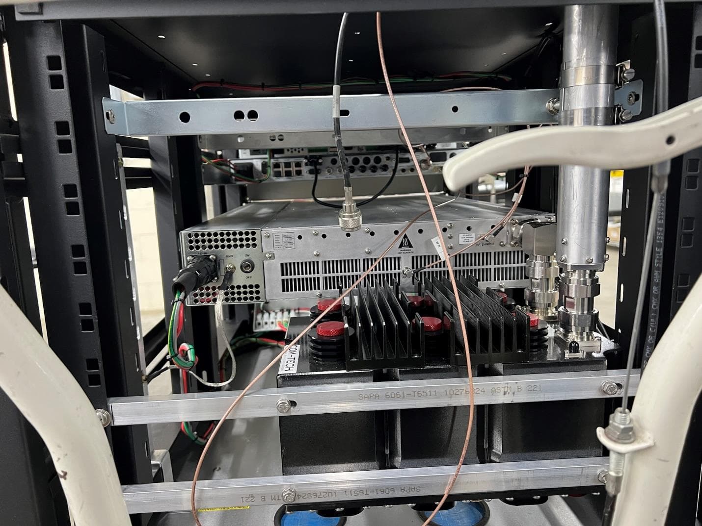
LYIEC704MPBB3
Apr 04, 2022Broadcast Transmitter
Equipment Class
TBC - Licensed Broadcast Station Transmitter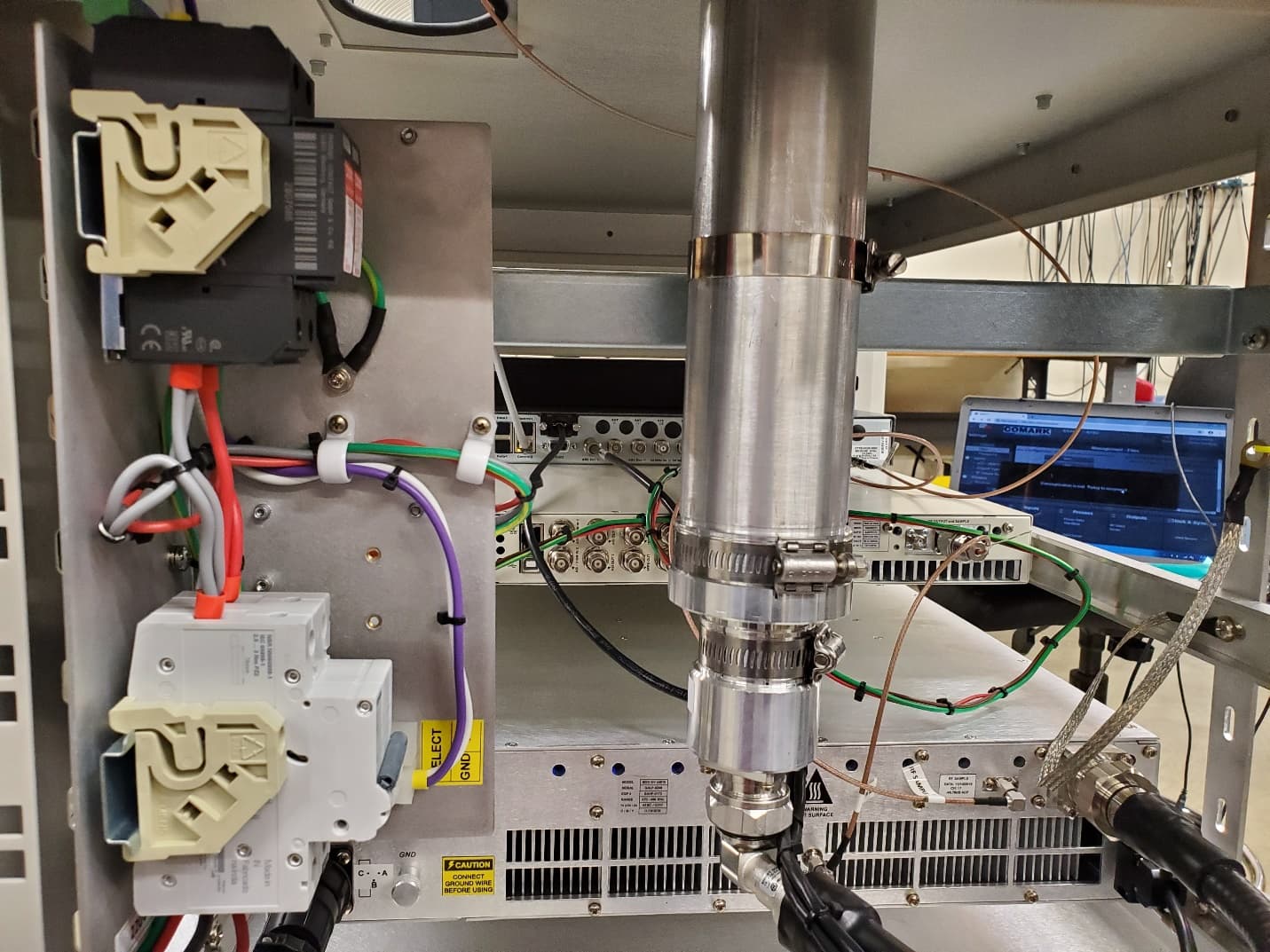
LYIEC702MP
Feb 09, 2021215 Watts ATSC3.0 / 225 Watts ATSC1.0 Transmitter System
Equipment Class
TBC - Licensed Broadcast Station Transmitter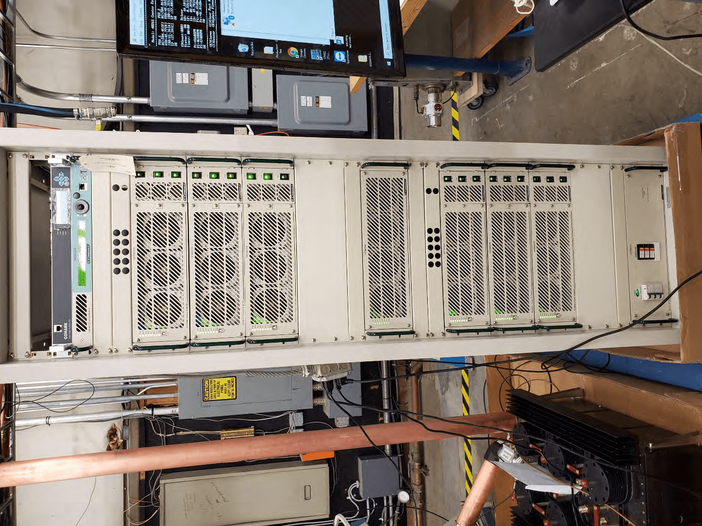
LYIEC706HPBB2
Feb 04, 20216600W/5700W ATSC 1.0/3.0 Transmitter System
Equipment Class
TBC - Licensed Broadcast Station Transmitter
LYIAT7400
Dec 18, 2006400W UHF ATSC Transmitter - Advanced TV
Equipment Class
TBC - Licensed Broadcast Station Transmitter
LYIAT7200
Dec 12, 2006200W UHF ATSC Transmitter - Advanced TV
Equipment Class
TBC - Licensed Broadcast Station Transmitter