LYIEC702MP215 Watts ATSC3.0 / 225 Watts ATSC1.0 Transmitter System
Hitachi Kokusai Electric America LTD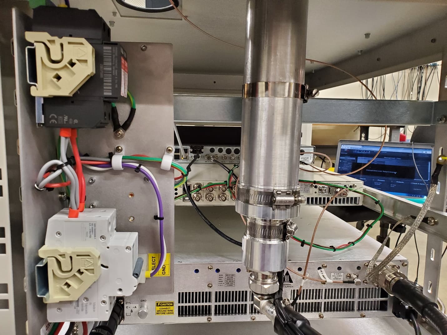
Click to zoom
Application Details
- Equipment Class
- TBC - Licensed Broadcast Station Transmitter
- Date of Grant
- Feb 09, 2021
- Application Purpose
- Original Equipment
- Date of Application
- Feb 09, 2021
- Equipment Note
- 215 Watts ATSC3.0 / 225 Watts ATSC1.0 Transmitter System
- Frequency Range
- 470.00000000 - 608.00000000
- Country
- United States
Documents & Files
Document Text
Text extracted from the exhibit documents filed with the FCC. Open a document above to read the original.
Users Manual
1 | 106 E-Compact Medium Power Operation Manual UHF Digital TV Transmitters ATSC 3.0: 150 to 300 Watts RMS ATSC 1.0: 170 to 350 Watts RMS E-Compact Medium Power Series Read before handling the equipment. EC702MP EC704MP 2 | 106 E-Compact Medium Power Operation Manual UHF Digital TV Transmitters ATSC 3.0 • 150 to 300 Watts RMS ATSC 1.0 • 170 to 350 Watts RMS E-Compact Medium Power Series EC702MP • EC704MP Rev R00 – EN-US All rights reserved Hitachi Kokusai Linear Equipamentos Eletrônicos S/A CNPJ: 19.690.445/0001-79 Rodovia BR 459, Km 121, 121A – Córrego Raso - Santa Rita do Sapucaí - MG - Brazil – CEP 37540-000 Phone: +55 35 3473 3473 - [email protected] www.hitachi-linear.com.br W A R N I N G All rights are reserved to Hitachi Kokusai Linear Electronic Equipment S/A, thus any reproduction, adaptation, translation or misuse of this Manual without prior written permission is prohibited, except as permitted by copyright laws. 3 | 106 E-Compact Medium Power CONTENTS 1.Index CONTENTS ........................................................................................................... 3 1.Index ................................................................................................................................................................ 3 1.About this Manual .......................................................................................................................................... 8 2.Basic Knowledge Required ........................................................................................................................... 9 3.Structure .......................................................................................................................................................... 9 Section 1 - Care, Warranty, and Service ............................................................................................................... 10 1.Care and Safety ............................................................................................................................................ 10 2.Warranty. ....................................................................................................................................................... 11 3.Technical Assistance. .................................................................................................................................. 12 Section 2 - Minimum Installation Requirements .................................................................................................... 13 1.Introduction................................................................................................................................................... 14 2.Minimum Requirements. .............................................................................................................................. 14 2.1. AC Mains - Wire Gauge. ....................................................................................................................... 14 2.2. Grounding. ............................................................................................................................................ 14 2.3. Stability. ................................................................................................................................................. 15 2.4. Insulation............................................................................................................................................... 15 2.5. Atmospheric Discharge Protection System. ..................................................................................... 18 2.5.1 Lightning rods. ............................................................................................................................. 18 2.5.2 Protectors. .................................................................................................................................... 18 2.6 Air Conditioning. .................................................................................................................................. 18 2.6.1 Temperature. ................................................................................................................................. 18 2.6.2 Humidity. ....................................................................................................................................... 19 2.6.3 Co o ling. ......................................................................................................................................... 19 Section 3 – E-Compact Medium Power Series UHF Digital TV Transmitters ....................................................................................................... 20 1.Overview........................................................................................................................................................ 20 2.Specifications ............................................................................................................................................... 21 3.Construction ................................................................................................................................................. 23 4.Footprint ........................................................................................................................................................ 26 2.1 FCC Compliance. .................................................................................................................................. 11 4 | 106 E-Compact Medium Power 5.Block Diagram .............................................................................................................................................. 27 6.Main Modules ................................................................................................................................................ 29 6.1. CM8001 Control Module (MOD GV 40056) .....................................…
Text truncated - open the document above for the full version.
Users Manual
Document Reference: MPD-1611291-A USER MANUAL MPD-1611291-A EXACT-V2 High End Rack Modulator / Exciter 3/10/2017 MPD-1611291-A Page 2/94 USER MANUAL MPD-1611291-A EXACT-V2 High End Rack Modulator / Exciter 3/10/2017 MPD-1611291-A Page 3/94 Table of Content 1 System Overview 9 1.1 General overview .......................................................................... 11 1.2 Block diagram .............................................................................. 12 2 Features Summary 13 2.1 Features Overview ........................................................................ 15 2.2 Input Stream Interfaces ................................................................ 17 2.2.1 ASI/SMPTE Inputs ......................................................................... 17 2.3 Input Stream Management ............................................................ 17 2.3.1 TS CleverSwitch Control ................................................................ 18 2.3.2 Seamless Switching ...................................................................... 19 2.4 Modulation Core ........................................................................... 19 2.5 Test modes operation .................................................................... 19 2.5.1 PRBS sequence ............................................................................. 19 2.5.2 Sinus tone generation ................................................................... 19 2.6 Digital Precorrection ...................................................................... 20 2.6.1 Digital Adaptive Precorrection ......................................................... 22 2.6.2 Manual Digital Pre-correction ............................................................. 25 2.6.3 Adaptive Linear pre-correction for sharp channel filters (in ATSC 1.0) ..... 25 2.7 Output Processing ......................................................................... 26 2.7.1 RF output muting and RF maintain features...................................... 26 2.7.2 Crest Factor Reduction Management ............................................... 27 2.7.3 DAP Operation .............................................................................. 30 2.8 Clock and Synchronization ............................................................. 32 2.8.1 GPS and clock management for VX20-x0x2 ...................................... 32 2.8.2 Warm-up Time ............................................................................. 35 2.8.3 Loss of Reference Signal management (LORS) ................................. 35 2.9 Power Measurements .................................................................... 37 2.10 Automatic Gain Control (AGC) ........................................................ 38 3 EXACT-V2 Rack 39 3.1 EXACT-V2 mechanics .................................................................... 41 3.1.1 Front panel layout ......................................................................... 41 3.1.2 Rear Panel Layout ......................................................................... 42 3.2 Interface characteristics ................................................................ 42 3.3 Front Panel signalization (LEDs description) ..................................... 52 3.4 Power requirements ...................................................................... 53 3.5 Performances and technical characteristics ....................................... 53 3.5.1 General characteristics .................................................................. 53 3.5.2 Control and data Ethernet interfaces ............................................... 53 3.5.3 Serial control interfaces ................................................................. 54 3.5.4 ASI inputs / output and MPEG-TS processing .................................... 55 3.5.5 Digital modulation ......................................................................... 56 3.5.6 Clock synchronization .................................................................... 57 3.5.7 RF and monitoring outputs ............................................................. 59 USER MANUAL MPD-1611291-A EXACT-V2 High End Rack Modulator / Exciter 3/10/2017 MPD-1611291-A Page 4/94 3.5.8 Digital precorrection ...................................................................... 60 3.5.9 Power level measurement inputs and AGC ........................................ 61 3.5.10 Dry contacts ............................................................................... 61 3.6 Conformity with EC Directive .......................................................... 62 4 EXACT-V2 Installation 63 4.1 Unpack the Unit ............................................................................ 65 4.2 Installation and Recommendations .................................................. 65 4.2.1 Temperature alarms ...................................................................... 66 4.2.2 Cooling methods ........................................................................... 66 4.3 Wiring and Powering on.................................................................. 66 4.4 Initial Configuration ....................................................................... 67 5 Operation 71 5.1 Operation Generalities ................................................................... 73 5.1.1 Local Operation ............................................................................. 73 5.1.2 Remote Operation ......................................................................... 73 5.2 Embedded Web GUI Description ...................................................... 74 5.2.1 Requirements ............................................................................... 74 5.2.2 Connection to EXACT-V2 ................................................................ 74 5.2.3 General Overview .......................................................................... 75 5.2.4 Setti…
Text truncated - open the document above for the full version.
Cover Letter(s)
$Hitachi Kokusai Electric Comark LLC 8/26/2020 Federal Communications Commission Authorization & Evaluation Division 7345 Oakland Mills Road Columbia, Maryland 21046 2 RE: Long-Term Confidentiality Request for EC-702MP FCC ID LYIEC702MP To Whom It May Concern: This letter serves as an official request for confidentiality under§ 0.457(d) and§ 0.459 of CFR 47. We have requested that the following documents required to be submitted with this application be permanently withheld from public review. • Schematics • Parts List • Internal Photos •Block Diagram These documents contain detailed system and equipment descriptions and related information a bout the product, which manufacturer/applicant considers to be proprietary, confidential, and a custom design and otherwise, would not release to the general public. Since this design is a basis from which future technological products will evolve, manufacturer/applicant feels that this information would be of benefit to its competitors, and that the disclosure of the information in th ese documents would give our competitors an unfair advantage in the market. These are professional broadcast transmitters that are permanently installed in television broadcast facilities, and as such are not readily accessible to the public. The information in these documents are not part of the user manual, and are supplied only if necessary, in compliance with the requirements of Article 7, "Disclosure And Use of Confidential or Proprietary Information", of our standard terms and conditions for sale. This article is provided as an exhibit to this submission. Please contact me if there is any information you may need. �/)� Thomas R. Barbeau Vice President of Engineering Hitachi Kokusai Electric Comark, LLC 104 Feeding Hills Road Southwick, MA 01077 - USA Tel: (413 ) 998-1100, Fax. (413) 998-1194 www.comarktv.com COMARK
External Photos
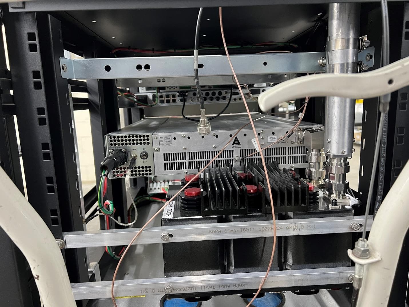
Figure 1. EC702MP Front View Figure 2. EC702MP Rear View F igure 3. Exact V2 Exciter Front View F igure 4. Exact V2 Exciter Rear View F igure 5. Transmitter Control Module Front View Fi gure 6. Transmitter Control Module Rear View
ID Label/Location Info
FCC ID Label for EC-702MP FCC ID Label Location
Operational Description
Operational Description: The EC-702MP digital transmitter system is an up to 170W average power (when using ATSC 1.0 8VSB modulation), 150W average power (when using ATSC 3.0 COFDM modulation) that consists of a Hitachi Kokusai Electric Comark (HKCM) Exact V2 digital exciter, Hitachi Kokusai Electric Linear (HKL) CM-8001 Drive controller, one (1) HKL GV40033A Amplifier, a passive hybrid combining system, an HKL 40243 Low pass filter, and a Com-Tech FC6D60C 6 Pole Mask Filter (or equivalent or more stringent fil ter). The final stage of amplification operates at 50VDC and 20A at full power. This system is used to provide an ATSC 1.0 (8VSB) or ATSC 3.0 (COFDM) modulated signal over the UHF channels 14 through 36 in a manner consistent with FCC Part 74. Output power from, maximum power to 0W depending on the modulation standard, is controlled via attenuator circuitry in the CM-8001 Drive controller.
Parts List/Tune Up Info
REV A — 25 April, 2019 1 Technical Service Bulletin 190425 RF Tuning Procedure for Transmitters Using Exact V2 Exciter The Comark Exact exciter has a very capable / powerful non-linear digital pre-corrector con- tained in it. Knowing how to set up and properly adjust this corrector is key to the best perfor- mance and safe operation of a transmitter. Described below is a basic guide to allow a user to accomplish the proper tuning adjustment of this corrector. 1. Overview Panel First insure that the transmitter is properly connected to the output mask filter and load. Ensure that you have RF output couplers in the path before and after the mask filter for transmitter feed- back to the Exact exciter. Log into the Exact Exciter’s webpage and configure the correct output modulation type, bandwidth, and frequency in the RF Output Parameters tab. 2. Basic Setup On the rear panel there are 2 SMA connectors labeled FBA (Feed Back Amplifier), and FBF (Feed Back Filter). The FBA signal should come from the transmitter output sample before the mask filter. This is used for non-linear (shoulder) correction. The FBF signal should come from the transmitter output sample after the mask filter. This is used for linear (SNR) correction. These signal levels should be in the range of -15 to -5 dBm. 3. Connecting Feedback Signals Fig. 1 Rear panel REV A — 25 April, 2019 2 Technical Service Bulletin 190425 4. Checking the Feedback Signals Levels Once the feedback signals are connected, the user can check, in the Exact Precorrections Menu, that they are properly wired, synchronized, and that their power levels are in accordance with the specifications. Fig. 2 Exact Precorrections screen 5. Connecting Feedback Signals The only parameters that need to be set before launching the DAP are Crest Factor, Protection Clipping, and Timer (Correction Time). 6. Crest Factor Setting Since the Exact is performing a clever PAPR reduction, less destructive for the signal compared to the amplifier, the Crest Factor has to be reduced as much as possible by Exact instead of the amplifier. As a tool, the Crest Factor value monitored from the amplifier feedback signal can be used as a guide / starting point. Once the transmitter is at full power and before correction is run for the first time, the crest factor / PAPR can be read in the FBA Measurements section of the Corrections page. This is the Crest Factor / PAPR that the Exact is measuring on the transmitter output without correction. The recommended starting point is to set the Crest Factor setting only about 1dB higher than the value which is monitored in the FBA Measurements sec- tion. This should not be set to what you believe the Crest Factor / PAPR should be when you are finished correcting or as referenced by any other measurement means. 7. Protection Clipping Setting Protection Clipping is just what the name implies. It is the maximum level of PAPR allowed out of the exciter when correction is run. Because the DAP corrector simply tries to make the feed- back signal as close to perfect as possible it essentially knows no limits of how far it can stretch peaks unless told otherwise. If this is not kept to a “reasonable” level it could result in amplifier damage. A good guideline is to keep this only about 3dB above the crest factor setting. Once REV A — 25 April, 2019 3 Technical Service Bulletin 190425 Once the Crest Factor and Protection Clipping have been set, the DAP can be launched in the Precorrection Menu, using one of the following modes: “Single” mode (recommended), where the DAP will be automatically stopped after a user config- urable “Timer” value. “Continuous” mode, where the DAP works continuously until the user exit the continuous mode 7. Protection Clipping Setting cont. correction has run, it should be adjusted down by 1dB from where it is set to see if there is a performance impact. If not, then leave it alone. It should only be carefully increased in small increments to see if increasing has any positive effect on signal performance. Essentially, it should be adjusted only as high as necessary to achieve acceptable performance. Fig. 3 Non Linear Precorrections screen followed by the RF Output Parameters screen 8. Timer Setting In the Precorrections menu if “Single” mode is selected the amount of time the corrector will run can be adjusted. In most cases 3 to 5 Minutes is sufficient for good performance of the non-lin- ear corrector. By not setting the value too low or short, the shoulder performance may not reach its best performance level as the corrector has not run enough iterations of correction to linear- ize the transmitter optimally. By setting it excessively high or long, the transmitter performance will have already reached the optimum performance before the corrector has stopped. Setting it too long can potentially have ill effects in that the shoulders could become “over corrected” and not be at optimum performance. 9. Crest Factor Parameter Setting Fine Tuning After a first run of DAP (in “single” mode with a timer value set), it is usually possible to fine tune the Crest Factor setting in order to improve the achieved shoulders performance. This change should be made in small increments (0.1 to 0.3dB) either up or down from the original set value while observing the shoulder performance. If the performance gets better, try going a little more in that direction until the performance starts to degrade then back up a bit to the best performance. Once this is done, reset the correction, and re-run the DAP. This should yield equal or perhaps slightly better performance. The corrector is now optimally adjusted. REV A — 25 April, 2019 4 Technical Service Bulletin 190425 10. Crest Factor Optimization Parameter Setting For a given “Crest Factor”, the “Crest Factor Optimization” enhances the signal shoulders. Find- ing the best value for this parameter allows the user to gain performance on the shoulders of the signal, thus optimizing the amplifi…
Text truncated - open the document above for the full version.
Test Report
P20b0005_FCC_Part 74_Rev 2.0 Page 1 of 22 Test Report Prepared for: Hitachi Kokusai Electric Comark Model: EC702MP Exact V2 Exciter Description: Broadcast Transmitter FCC ID: LYIEC702MP To FCC Part 74 Date of Issue: January 20, 2021 On the behalf of the applicant: Hitachi Kokusai Electric Comark 104 Feeding Hills Rd Southwick, MA 0107701077 Attention of: Thomas Barbeau, VP of Engineering Ph: (413)998-1124 E- Mail: [email protected]@comarktv.com Prepared By Compliance Testing, LLC 1724 S. Nevada Way Mesa, AZ 85204 (480) 926-3100 phone / (480) 926-3598 fax www.compliancetesting.com Project No: p20b0005 Greg Corbin Project Test Engineer This report may not be reproduced, except in full, without written permission from Compliance Testing. All results contained herein relate only to the sample tested. P20b0005_FCC_Part 74_Rev 2.0 Page 2 of 22 P20b0005_FCC_Part 74_Rev 2.0 Page 3 of 22 Test Report Revision History Revision Date Revised By Reason for Revision 1.0 October 6, 2020 Greg Corbin Original Document 2.0 February 1, 2021 Greg Corbin Corrected typo for rule section in test summary table on page 8 P20b0005_FCC_Part 74_Rev 2.0 Page 4 of 22 Table of Contents Description Page Standard Test Conditions and Engineering Practices 6 Test Result Summary 8 Power Limitations (Output Power) 9 Emission Mask 11 Occupied Bandwidth 13 Conducted Spurious Emissions 15 Field Strength of Spurious Radiation 19 Frequency Stability (Temperature Variation) 20 Measurement Uncertainty 22 Test Equipment Utilized 23 P20b0005_FCC_Part 74_Rev 2.0 Page 5 of 22 ANAB Compliance Testing, LLC, has been accredited in accordance with the recognized International Standard ISO/IEC 17025:2017. This accreditation demonstrates technical competence for a defined scope and the operation of a laboratory quality management system (refer to the joint ISO-ILAC-IAF Communiqué dated January 2009). The tests results contained within this test report all fall within our scope of accreditation, unless noted below. Please refer to http://www.compliancetesting.com/labscope.html for current scope of accreditation. Testing Certificate Number: 2152.01 FCC Site Reg. #349717 IC Site Reg. #2044A-2 Non-accredited tests contained in this report: N/A P20b0005_FCC_Part 74_Rev 2.0 Page 6 of 22 Test and Measurement Data All tests and measurement data shown were performed in accordance with FCC Rules and Regulations, Volume II, Part 2, Subpart J, Sections 2.947, 2.1033(c), 2.1041, 2.1046, 2.1047, 2.1049, 2.1051, 2.1053, 2.1055, 2.1057, and the following individual Parts: FCC Part 74. Standard Test Conditions and Engineering Practices Except as noted herein, the following conditions and procedures were observed during the testing. In accordance with ANSI/TIA 603C, and unless otherwise indicated in the specific measurement results, the ambient temperature of the actual EUT was maintained within the range of 10° to 40°C (50° to 104°F) unless the particular equipment requirements specified testing over a different temperature range. Also, unless otherwise indicated, the humidity levels were in the range of 10% to 90% relative humidity. Environmental Conditions Temp (ºC) Humidity (%) Pressure (mbar) 23.5 – 27.2 13 – 21 962.2 – 964.7 Measurement results, unless otherwise noted, are worst-case measurements. EUT Description Model: EC 702MP, Exact V2 Exciter Description: Broadcast Transmitter Additional Information: The EC-702MP digital transmitter system is an up to 170W average power (when using ATSC 1.0 8VSB modulation), 150W average power (when using ATSC 3.0 COFDM modulation) that consists of a Hitachi Kokusai Electric Comark Exact V2 digital exciter, Hitachi Kokusai Electric Linear CM-8001 Drive controller, one (1) GV40033 Amplifier, a passive hybrid combining system, a 40243 Low pass filter, and a Com-Tech FC6D60C 6 Pole Mask Filter (or equivalent or more stringent filter). This system is used to provide an ATSC 1.0 or ATSC 3.0 modulated signal over the UHF channels 14 through 36 in a manner consistent with FCC Part 74. EUT Operation during Tests Conducted RF measurements were recorded after the 6 pole mask filter, via a RF coupler attached to the filter output. The coupler thru port was connected to a 10000 watt 50 ohm load. The EUT has 2 types of modulation, ATSC1.0 (8VSB) and ATSC 3.0 (OFDM). The system was tested with the manufacturer supplied Stringent Mask filter was tuned to 491 MHz (CH 17). All tests were performed with the tuned frequency set to 491 MHz. AC power is 230 VAC at 60 Hz. P20b0005_FCC_Part 74_Rev 2.0 Page 7 of 22 Model EC702MP Modulation ATSC 1.0 ATSC 3.0 Output Power (watts) 170 150 EC704MP System components Description Model S/N System EC702MP EAHO-0270 CM8001 Control Module MOD GV 40056A GAOK0166 Exact V2 High End TV Exciter XTTR-VX20-3002 00243 PA702MP Power Amplifier GV40033 GANQ0255/19 Low Pass Filter 40243 N/A 6-Pole Stringent Mask Filter 6PPXX80E 93731 Ethernet Switch DES-1024D N/A Accessories: Qty Description Manufacturer Model S/N 1 Precision RF Coupler Dielectric N/A N/A Cables: Qty Description Length (M) Shielding Y/N Shielded Hood Y/N Termination 1 manufacturer supplied cable set N/A N/A N/A N/A Modifications: None P20b0005_FCC_Part 74_Rev 2.0 Page 8 of 22 Test Result Summary Specification Test Name Pass, Fail, N/A Comments 74.735 2.1046 Power Limitations(Output Power) Pass 2.1047 Modulation Characteristics Pass Refer to page 5 74.794(a)(ii) 2.1051 Emission Masks (Stringent Mask) Pass Manufacturer supplied a stringent mask filter 2.1049 Occupied Bandwidth Pass 74.794(a)(ii) 74.975(b)(2) 2.1051 Digital Emissions (Conducted Spurious) Pass 74.794(b) 2.1051 Spurious Emissions, GPS bands Pass 74.794(b) 2.1053 Field Strength of Spurious Radiation Pass 74.794(b)(4) 2.1055 Frequency Stability (Temperature Variation) Pass 74.794(b)(4) 2.1055 Frequency Stability (Voltage Variation) Pass Statements of conformity are reported as: • Pass - the measured value is below the acceptance limit, acceptance limit = test limit. • Fail…
Text truncated - open the document above for the full version.
Test Report
P2060011_Annex A _ Rev 1.0 Page 1 of 12 Annex A Radiated Spurious Emissions P2060011_Annex A _ Rev 1.0 Page 2 of 12 Radiated Emission_1 - 7 GHz_ ATSC 1.0_1467 MHz Radiated Emission_1 - 7 GHz_ ATSC 1.0_1964 MHz P2060011_Annex A _ Rev 1.0 Page 3 of 12 Radiated Emission_1 - 7 GHz_ ATSC 1.0_2940 MHz Radiated Emission_1 - 7 GHz_ ATSC 1.0_3931 MHz P2060011_Annex A _ Rev 1.0 Page 4 of 12 Radiated Emission_1 - 7 GHz_ ATSC 1.0 Radiated Emission_1 - 7 GHz_ ATSC 3.0_1471 MHz P2060011_Annex A _ Rev 1.0 Page 5 of 12 Radiated Emission_1 - 7 GHz_ ATSC 3.0_1963 MHz Radiated Emission_1 - 7 GHz_ ATSC 3.0 P2060011_Annex A _ Rev 1.0 Page 6 of 12 Radiated Emission_30 - 1000 MHz_32.36 MHz Radiated Emission_30 - 1000 MHz_62.40 MHz P2060011_Annex A _ Rev 1.0 Page 7 of 12 Radiated Emission_30 - 1000 MHz_71.618 MHz Radiated Emission_30 - 1000 MHz_978.653 MHz P2060011_Annex A _ Rev 1.0 Page 8 of 12 Radiated Emission_30 - 1000 MHz_ ATSC 1.0 Radiated Emission_30 - 1000 MHz_ ATSC 3.0_37.3 MHz P2060011_Annex A _ Rev 1.0 Page 9 of 12 Radiated Emission_30 - 1000 MHz_ ATSC 3.0_63 and 72 MHz Radiated Emission_30 - 1000 MHz_ ATSC 3.0_981.745 P2060011_Annex A _ Rev 1.0 Page 10 of 12 Radiated Emission_GPS_1164 - 1215 MHz._ ATSC 1.0 Radiated Emission_GPS_1164 - 1215 MHz_ ATSC 3.0 P2060011_Annex A _ Rev 1.0 Page 11 of 12 Radiated Emission_GPS_1215 - 1240 MHz_ ATSC 1.0 Radiated Emission_GPS_1215 - 1240 MHz_ ATSC 3.0 P2060011_Annex A _ Rev 1.0 Page 12 of 12 Radiated Emission_GPS_1559 - 1610 MHz_ ATSC 1.0 Radiated Emission_GPS_1559 - 1610 MHz_ ATSC 3.0
Test Setup Photos
Page 1 of 3 Test Setup Photos FCC ID: LYIEC702MP RF Conducted #1 RF Conducted #2 Page 2 of 3 RF Radiated_ below 1 GHz RF Radiated_ below 1 GHz Page 3 of 3 RF Radiated_ above 1 GHz Frequency Stability
Contact Information
Applicant
Thomas Barbeau(VP of Engineering)
Technical Contact
Hitachi Kokusai Electric Comark LLCThomas Barbeau
[email protected]4139981124
104 Feeding Hills Rd · Southwick, Massachusetts · United States
Non-Technical Contact
Hitachi Kokusai Electric Comark LLCJoseph Turbolski
[email protected]4139981314
Test Firm
Compliance Testing, LLCMichael Schafer
[email protected]480-926-3100
Technical Specifications
| # | Rule Parts | Frequency Range | Power Output | Emission | Tolerance |
|---|---|---|---|---|---|
| 2 | 74 | 470 MHz - 608 MHz | 170.4 W | 5M52C7W | 25 Hz |
Other Applications from Hitachi Kokusai Electric America LTD
LYIEC704MPBB3
Apr 04, 2022Broadcast Transmitter
Equipment Class
TBC - Licensed Broadcast Station Transmitter
LYIEC706HPBB2
Feb 04, 20216600W/5700W ATSC 1.0/3.0 Transmitter System
Equipment Class
TBC - Licensed Broadcast Station Transmitter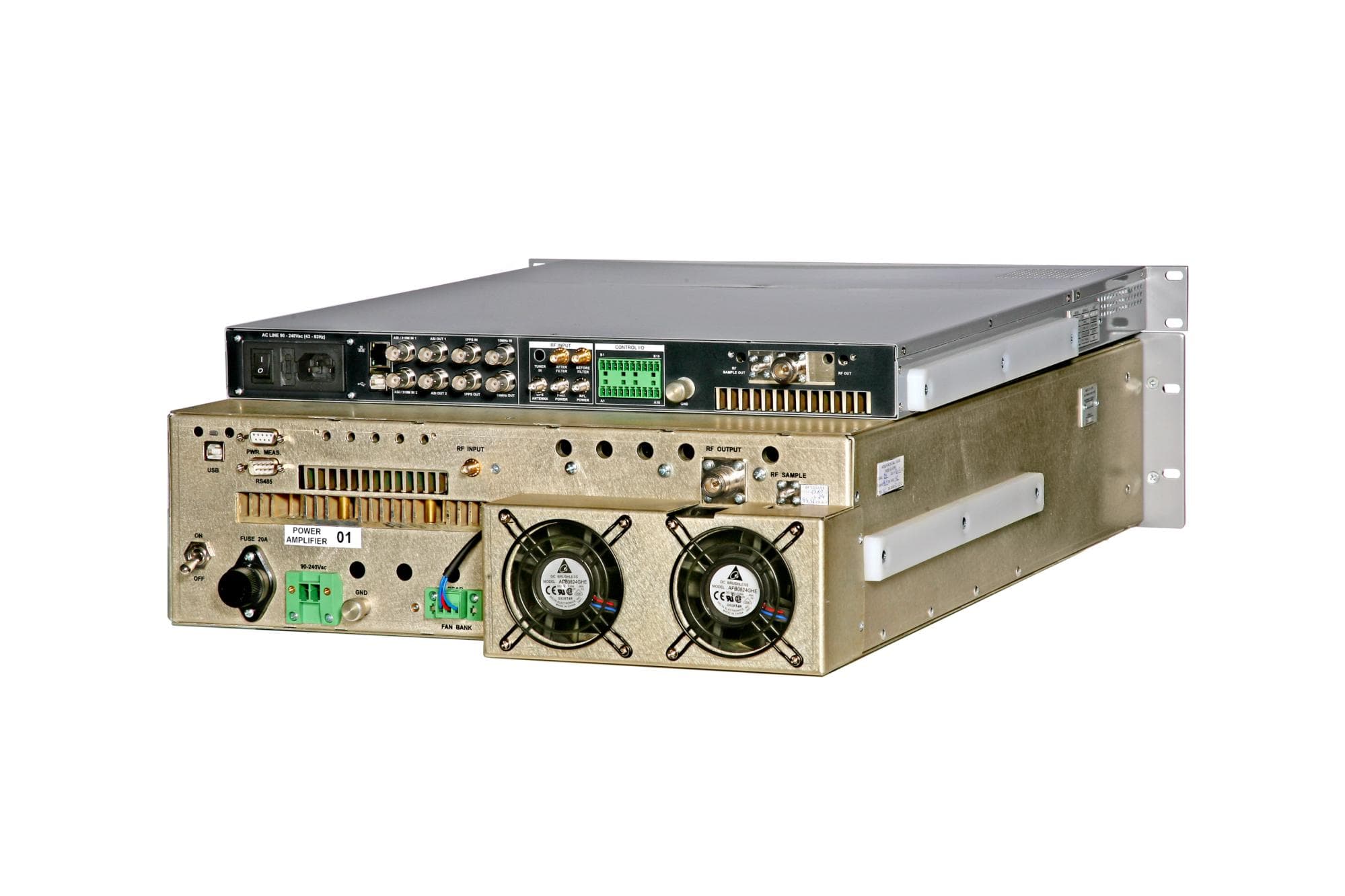
LYIAT1251
Mar 18, 2013250W UHF ATSC Transmitter
Equipment Class
TBC - Licensed Broadcast Station Transmitter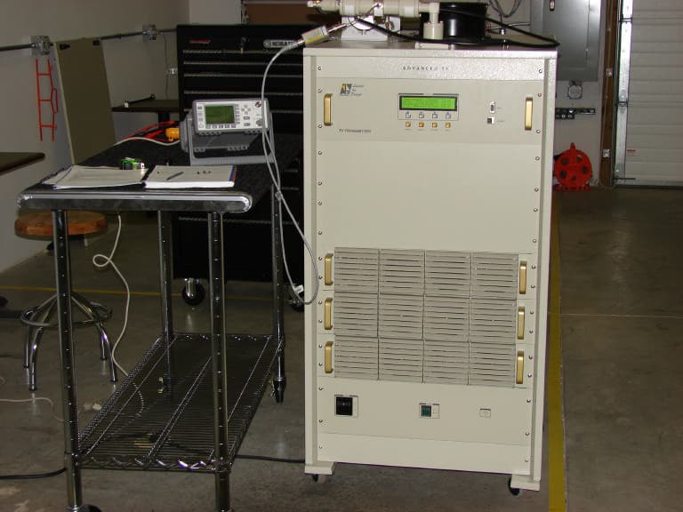
LYIAT7400
Dec 18, 2006400W UHF ATSC Transmitter - Advanced TV
Equipment Class
TBC - Licensed Broadcast Station Transmitter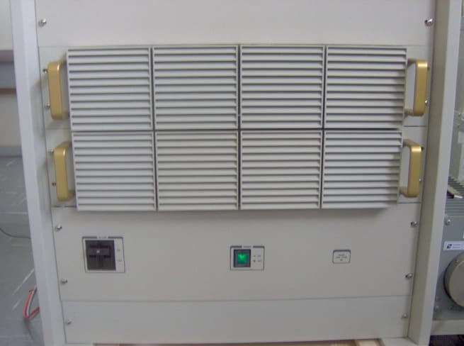
LYIAT7200
Dec 12, 2006200W UHF ATSC Transmitter - Advanced TV
Equipment Class
TBC - Licensed Broadcast Station Transmitter