M39LRXXRFID Communicator
Tagmaster AB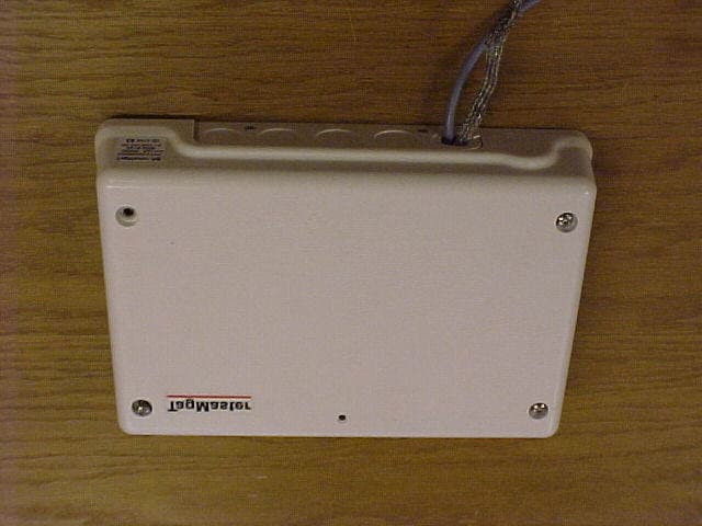
Click to zoom
Application Details
- Equipment Class
- FDS - Part 15 Field Disturbance Sensor
- Date of Grant
- Jul 26, 2006
- Application Purpose
- Original Equipment
- Date of Application
- Jul 26, 2006
- Equipment Note
- RFID Communicator
- Frequency Range
- 2436.17000000 - 2464.04000000
- Company
- Tagmaster AB
- Country
- Sweden
Documents & Files
Document Text
Text extracted from the exhibit documents filed with the FCC. Open a document above to read the original.
Users Manual
Copyright The copyright/ownership of this document is and will remain ours. The document must not be used without our authorization or brought to the knowledge of a third party. TagMaster AB. Disclaimer The information in this document is subject to change without notice. While the information contained herein is assumed to be accurate, TagMaster AB assumes no responsibility for any errors or omissions. HW INSTALLATION GUIDE MANUAL ISSUE 05 DOC NO. 510278 2 FCC ID: M39LRXX This device complies with part 15 of the FCC Rules. Operation is subject to the following two conditions: (1) This device may not cause harmful interference, and (2) This device must accept any interference received, including interference that may cause undesired operation. NOTE: This equipment has been tested and found to comply with the limits for a Class A digital device, pursuant to part 15 of the FCC Rules. These limits are designed to provide reasonable protection against harmful interference when the equipment is operated in a commercial environment. This equipment generates, uses, and can radiate radio frequency energy and, if not installed and used in accordance with the instruction manual, may cause harmful interference to radio communications. Operation of this equipment in a residential area is likely to cause harmful interference in which case the user will be required to correct the interference at his own expense. Caution Information to user. Changes or modifications not expressly approved by the party responsible for compliance could void the user’s authority to operate the equipment. TagMaster AB HW Installation Guide ABOUT THIS DOCUMENT Manual issue 05 3 TABLE OF CONTENTS 1 ABOUT THIS DOCUMENT......................................................................................................5 1.1 Introduction......................................................................................................................5 1.2 Audience .........................................................................................................................5 1.3 Definitions........................................................................................................................5 1.4 References ......................................................................................................................6 1.5 Revisions .........................................................................................................................6 2 SAFETY INSTRUCTIONS.......................................................................................................7 2.1 General............................................................................................................................7 2.2 Installation .......................................................................................................................7 3 SYSTEM COMPONENTS.......................................................................................................9 3.1 Readers ...........................................................................................................................9 3.2 ID Tags ............................................................................................................................9 4 ENVIRONMENTAL CONSIDERATIONS ..............................................................................10 4.1 General..........................................................................................................................10 4.2 Electromagnetic immunity .............................................................................................10 4.3 Temperature..................................................................................................................10 4.3.1 Readers....................................................................................................................10 4.3.2 Tags ..........................................................................................................................10 5 MECHANICAL INSTALLATION.............................................................................................11 5.1 General..........................................................................................................................11 5.2 Readers .........................................................................................................................11 5.2.1 Mounting ...................................................................................................................11 5.2.2 Cables.......................................................................................................................11 5.3 ID-Tags..........................................................................................................................11 5.4 Accessories ...................................................................................................................12 5.5 Typical installations .......................................................................................................13 5.5.1 Single lane identification ...........................................................................................13 5.5.2 Multi lane identification..............................................................................................13 5.5.3 How to handle and mount the tag.............................................................................13 6 ELECTRICAL INSTALLATION ..............................................................................................14 6.1 General..........................................................................................................................14 6.2 Connection diagrams ....................................................................................................16 6.2.1 Single Communicator connection using port A for RS232C.....................................16 6.2.2 Single …
Text truncated - open the document above for the full version.
Users Manual
Copyright The copyright/ownership of this document is and will remain ours. The document must not be used without our authorization or brought to the knowledge of a third party. TagMaster AB. Disclaimer The information in this document is subject to change without notice. While the information contained herein is assumed to be accurate, TagMaster AB assumes no responsibility for any errors or omissions. S1500 / S1501 Reader User programmable Read/Write station DATA SHEET DOC NO. 06-xxx 01 TagMaster AB S1500 / S1501 Reader Data Sheet Issue 01 Functional description S1500 readers are a 2.45 GHz circular polarised read/write station for TagMaster RFID tags. Reading distance is typically up to 6 metres. The reader has 99 RF channels to eliminate interference of other nearby readers. Transmitted power and reception sensitivity is also adjustable with SW commands for optimising any installation. S1500 has a movement detection function for detecting people and vehicles, or even smaller objects, even if not using a tag. It can determine their moving speed in approaching or retreating directions. S1500 is user programmable and has a large memory for application programs and built in database functions for fast, customised and efficient stand-alone operation. User software is downloaded and saved in EEPROM through a serial communication line. If user programming is not required, there is a ready-to-use standard application SW in the reader. A local database in EEPROM can be loaded with over 15,000 tag entries for extremely fast read- validate-activate response times. The ConfiTalk protocol is used for serial communication in a polled RS485 network or point-to-point in RS232 connections. There are ConfiTalk communication drivers available for 95/98/ME and NT/2000/XP with interface for C/C++, Delphi and Visual Basic. S1500 has two serial ports, a DTMF port for keypads, LED interfaces, relay, parallel I/O (emulating magcard data as an option). A control panel with a 7-segment LED display, two push buttons, a three colour LED, a buzzer and a reset button is available for local configuration and start up of test programs as installation aids. The unit can also be configured using a hand held computer or terminal connected locally. S1500 is sealed from water spray and dust. Non- corrosive materials are used in external parts. Connections are made through rubber bushings, or via cable glands in a steel back plane. Jackable screw connectors connect the wires. Built in DC/DC converters tolerate noisy voltages, provide low power consumption (3W) and can be set to 24 as well as 12 V DC Microwave/Antenna block Processor block I/O block DC supply RS 485 RS 232a RS 232b DTMF/LED Relay Opto I/O Radiated 2.45 GHz signal 6 m reading range Range/channel setting by SW Tag programming Movement detection at up to 5 m 3-colour LED and buzzer RS232 and 2/4 wire RS485 3 parallel in, 2 parallel out optoisolated. Relay and tamper switches EMI tolerant DC/DC conv. 24V or 12V powering User programmable C, Delphi and VB drivers Flash EEPROM database DTMF and LED interface Maintenance functions TagMaster AB S1500 / S1501 Reader Data Sheet Issue 01 General S1500 comprises a plastic cover and a metal chassis for two PC boards, where the upper position carries a standard board and the lower is for an option board. A rubber gasket seals the unit. The standard board includes a Processor and I/O block with analogue and digital circuits, and is integrated with a Microwave and Antenna block. The antenna system is circular polarised and radiates through the front cover, with a lobe that is directed perpendicularly to the front surface of S1500. The lobe shape can be described as an ellipsoid with a circular cross section, as shown in the figure below. CONFIDENT The reading and writing distances depend on the tag type and on the power and sensitivity SW settings. Typically, S1500 can read TagMaster tags at up to 6 m distance. See Reading/Writing range for details. When dismounting the cover, it separates from the cable inlets to conveniently operate the unit also without cover. Screw connectors are jackable and in logical groups, i.e. it is not needed to disconnect each wire to replace the electronics. J1 DTMF, LED, external tamper line J2 RS232 for terminal J3 RS232 and RS 485 for host J4 Parallel out and relay J5 Parallel in J6 DC supply To hide the cables, S1500 can be connected via cable glands in the back plane. Dual tamper switches monitor that the cover is closed. When removed, a software as well as hardware alarm is generated. For service and setup purposes there is a control panel with a 7-segment LED display, 2 control buttons, a reset button, a LED and a buzzer. There are also jumpers for RS232/485 and 12/24V selection. A corrosion resistant mounting bracket that gives additional sealing for rough environments is separately available. It fits the mounting holes of S1500, and has a flexible joint for easy adjustment to different mounting angles. J1J2J3J4J5J6 8,7 236,6 120,0 23,7 Diameter of holes: 4,2 mm TagMaster AB S1500 / S1501 Reader Data Sheet Issue 01 Copyright The copyright/ownership of this document is and will remain ours. The document must not be used without our authorization or brought to the knowledge of a third party. TagMaster AB. Disclaimer The information in this document is subject to change without notice. While the information contained herein is assumed to be accurate, TagMaster AB assumes no responsibility for any errors or omissions. Reading/writing range The maximum reading or writing range is defined as the maximum distance along the radiation axis where the tag can be communicated when the tag and reader face each other and when there is free space in between. The free space reading range for S1500 is up to more than 6 m (20 Ft). In a typical installation the reading range is up to 4m (13 Ft) Writing range is up to 0.25 m (0.8 Ft) The reading range depends on the tag reflectivity, the data speed (high…
Text truncated - open the document above for the full version.
Cover Letter(s)
TagMaster AB REPORT Approved by Document id Revision Mikael Willgert 06-039 01 Issued by Date Page Per Selin 2006-02-13 1 (1) _____________________________________________________________________________ ________________________________________________________________________ The copyright/ownership of this document is and will remain ours. The document must not be used without our authorization or brought to the knowledge of a third party. TagMaster AB. g:\avd\540\certif\u.s.a\fcc rf ansökningar\tagmaster\m39lrxx documents_1\06-039 01 m39lrxx model differences.doc Based on form 03-237 01 Description of Model Differences All variants are based on the same architecture i.e. the same RF-unit and the same base band functionality. The difference between variants is mainly: • Enclosure • External interfaces • Application SW 1 S1500 and S1501 S1501 is a slimmed version of S1500 with the following differences • 128 Kbytes EEPROM for code only. No EEPROM database. • No 7-segment display. • No buzzer. • No support for 4 wire RS485. • 12V supply only • No real time clock • No option board connector 2 S1503, S1504, S1513, S1514 These variants are specified for greater reading range and higher sealing class than S1500. S1503 and S1513 are based on the same configuration as S1500 while S1504 and S1514 are based on S1501. The output power for S1503 and S1504 is limited to 10 mW EIRP to suit a global market in the frequency range of 2435 – 2465 MHz. S1513 and S1514 can be configured with higher output power and different frequency range to comply with regulations on specific markets. 3 S1566 A heavy-duty reader for harsh environments. The reader can be configured as S1500 or S1501.
Cover Letter(s)
Review comments 1. Our RFID reader can as said act in two different modes. Both reading RFID and also as a movement detector. The movement detection function does not require an RFID-tag. It will detect the movement of any object as long as it reflects radio waves. Some of our customers use the reader for movement detection and also for reading tags in case there is a tag present. The reader is all the time capable of reading both stationary and moving tags. The FDS-function is used to measure the movement speed and to detect objects that are not tagged. We would like to have our reader approved according to both 15.245 and 15.247 2. The device is intended for both indoor and outdoor use. The exposure calculation has to be updated. See 4. below 3. a) To comply with FCC 15.247 The device has been tested in ETL Semko Report No 500209R1- 1 500209R1-2 and 500209R1-3. The three different devices were tested in the interval 2402 MHz – 2482 MHz b) To comply with FCC 15.245 The device has been tested in ETL Semko Report No 520634R1- 1 520634R1-2 520634R1-3 The three different devices were tested in the interval 2436,17 to 2464,04 MHz 4. Our intention has been to use up to 500 mW for FCC 15.247 and use up to 75 mW for 15.245. We have the understanding that up to 75 mW can be used according to 15.245. Our idea is that the power can be set in the factory to any power up to these maximum level according to the option selected by customer. The product that is described in the chapter "Electrical data" is set to use just 10 mW. I would assume that the RF exposure calculation should be based on 500 mW.
External Photos
1(2) External photos TagMaster FCC ID: M39LRXX S1500, S1501 S1503, S1504, S1513 and S1514 2(2) S1566
External Photos
1(2) External photos TagMaster FCC ID: M39LRXX S1500 S1513 2(2) S1566
ID Label/Location Info
TagMaster AB DESCRIPTION Approved by Document id Revision Mikael Willgert 06-033 02 01 Issued by Date Page Per Selin 2006-02-08 1 (1) _____________________________________________________________________________ ________________________________________________________________________ The copyright/ownership of this document is and will remain ours. The document must not be used without our authorization or brought to the knowledge of a third party. TagMaster AB. g:\avd\540\certif\u.s.a\fcc rf ansökningar\tagmaster\m39lrxx documents_1\06-033 02 m39lrxx marking labels.doc Based on form 03-237 01 S1500/00 Rev 05 TagMaster AB COMMUNICATOR FCC ID: M39LRXX 04 36 32755 DC 24V MAX 1A S1503/00 TagMaster AB Communicator Revision 05 FCC ID: M39LRXX 070814159 DC 24V MAX 1A S1504/00 TagMaster AB Communicator Revision 05 FCC ID: M39LRXX 070814159 DC 12V MAX 1A M39LRXX Internal photos 1 S1500, S1501 2 S1503, S1504, S1513, S1514 3 S1566 TAGMASTER AB Manufacturer TagMaster AB Type Communicator S1566/00 rev05 Serial no. FCC ID: M39LRXX Power supply 12V 24V max.1A 0413 2,5 2,5 60 30 0 2 2,7 6,5 8 11 14 18 21 24 28 0 11 16 33 65 35 Arial (11) Bold, Underlined Arial (7) Arial narrow (11) (mm) 2.7 (4x) S1501/00 Rev 05 TagMaster AB COMMUNICATOR FCC ID: M39LRXX 04 36 32755 DC 12V MAX 1A
ID Label/Location Info
1(2) Marking plate location, Tagmaster FCC ID: M39LRXX S1566 S1503, S1504, S1513 and S1514 2(2) S1500 and S1501
Internal Photos
TagMaster AB REPORT Approved by Document id Revision Mikael Willgert 06-030 01 P01A Issued by Date Page Per Selin 2006-02-03 1 (7) _____________________________________________________________________________ ________________________________________________________________________ The copyright/ownership of this document is and will remain ours. The document must not be used without our authorization or brought to the knowledge of a third party. TagMaster AB. g:\avd\540\certif\u.s.a\fcc rf ansökningar\tagmaster\m39lrxx documents_1\06-030 01 m39lrxx internal photos.doc Based on form 03-237 01 Internal photos over S1500 family revision 05 1 S1500 TagMaster AB REPORT Approved by Document id Revision Mikael Willgert 06-030 01 P01A Issued by Date Page Per Selin 2006-02-03 2 (7) _____________________________________________________________________________ ________________________________________________________________________ The copyright/ownership of this document is and will remain ours. The document must not be used without our authorization or brought to the knowledge of a third party. TagMaster AB. g:\avd\540\certif\u.s.a\fcc rf ansökningar\tagmaster\m39lrxx documents_1\06-030 01 m39lrxx internal photos.doc Based on form 03-237 01 2 S1513 TagMaster AB REPORT Approved by Document id Revision Mikael Willgert 06-030 01 P01A Issued by Date Page Per Selin 2006-02-03 3 (7) _____________________________________________________________________________ ________________________________________________________________________ The copyright/ownership of this document is and will remain ours. The document must not be used without our authorization or brought to the knowledge of a third party. TagMaster AB. g:\avd\540\certif\u.s.a\fcc rf ansökningar\tagmaster\m39lrxx documents_1\06-030 01 m39lrxx internal photos.doc Based on form 03-237 01 3 S1566 TagMaster AB REPORT Approved by Document id Revision Mikael Willgert 06-030 01 P01A Issued by Date Page Per Selin 2006-02-03 4 (7) _____________________________________________________________________________ ________________________________________________________________________ The copyright/ownership of this document is and will remain ours. The document must not be used without our authorization or brought to the knowledge of a third party. TagMaster AB. g:\avd\540\certif\u.s.a\fcc rf ansökningar\tagmaster\m39lrxx documents_1\06-030 01 m39lrxx internal photos.doc Based on form 03-237 01 4 CPU board 612481 TagMaster AB REPORT Approved by Document id Revision Mikael Willgert 06-030 01 P01A Issued by Date Page Per Selin 2006-02-03 5 (7) _____________________________________________________________________________ ________________________________________________________________________ The copyright/ownership of this document is and will remain ours. The document must not be used without our authorization or brought to the knowledge of a third party. TagMaster AB. g:\avd\540\certif\u.s.a\fcc rf ansökningar\tagmaster\m39lrxx documents_1\06-030 01 m39lrxx internal photos.doc Based on form 03-237 01 5 CPU board 612487 TagMaster AB REPORT Approved by Document id Revision Mikael Willgert 06-030 01 P01A Issued by Date Page Per Selin 2006-02-03 6 (7) _____________________________________________________________________________ ________________________________________________________________________ The copyright/ownership of this document is and will remain ours. The document must not be used without our authorization or brought to the knowledge of a third party. TagMaster AB. g:\avd\540\certif\u.s.a\fcc rf ansökningar\tagmaster\m39lrxx documents_1\06-030 01 m39lrxx internal photos.doc Based on form 03-237 01 6 RF board 612668 RF unit TagMaster AB REPORT Approved by Document id Revision Mikael Willgert 06-030 01 P01A Issued by Date Page Per Selin 2006-02-03 7 (7) _____________________________________________________________________________ ________________________________________________________________________ The copyright/ownership of this document is and will remain ours. The document must not be used without our authorization or brought to the knowledge of a third party. TagMaster AB. g:\avd\540\certif\u.s.a\fcc rf ansökningar\tagmaster\m39lrxx documents_1\06-030 01 m39lrxx internal photos.doc Based on form 03-237 01 7 RF board 612670 TX antenna
Test Setup Photos
1(6) TEST SET-UP PHOTOS FCC ID: M39LRXX Standard: FCC Part 15.245 Model: S1500 - Radiated spurious emission 30-1000 MHz 2(6) Model: S1500 - Radiated spurious emission 1-26 GHz Model: S1500 – Conducted disturbance voltage at AC terminal 3(6) Model: S1513 - Radiated spurious emission 30-1000 MHz 4(6) Model: S1513 - Radiated spurious emission 1-26 GHz Model: S1513 – Conducted disturbance voltage at AC terminal 5(6) Model: S1566 - Radiated spurious emission 30-1000 MHz 6(6) Model: S1566 - Radiated spurious emission 1-26 GHz
Contact Information
Applicant
Johan Franzen(Chief Technical Officer)
Technical Contact
Test Firm
Intertek SEMKO ABNiklas Bostrom
Technical Specifications
| # | Rule Parts | Frequency Range | Power Output |
|---|---|---|---|
| 1 | 15.245 | 2.44 GHz - 2.46 GHz | - |
Other Applications from Tagmaster AB
M39XTXX
Mar 30, 2014RFID reader
Equipment Class
DXT - Part 15 Low Power Transceiver, Rx Verified
M39S15XX
Oct 16, 2003RFID Reader
Equipment Class
FDS - Part 15 Field Disturbance Sensor