M39XTXXRFID reader
Tagmaster AB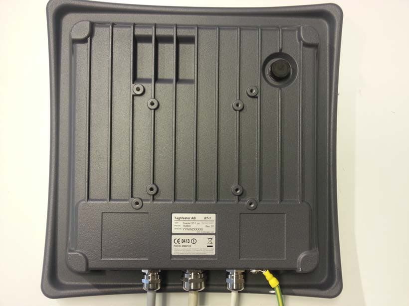
Click to zoom
Application Details
- Equipment Class
- DXT - Part 15 Low Power Transceiver, Rx Verified
- Date of Grant
- Mar 30, 2014
- Application Purpose
- Original Equipment
- Date of Application
- Mar 29, 2014
- Equipment Note
- RFID reader
- Frequency Range
- 902.75000000 - 927.25000000
- Company
- Tagmaster AB
- Country
- Sweden
Documents & Files
Document Text
Text extracted from the exhibit documents filed with the FCC. Open a document above to read the original.
Users Manual
XT-1 Installation Manual XT-1 Installation Manual 13-111 P01B, 2013-RO-0XX, 2014-01-28 Page 2 of 32 Note: This equipment has FCCID: M39XTXX. It complies with the limits for a Class A digital device, pursuant to part 15 of the FCC Rules. These limits are designed to provide reasonable protection against harmful interference when the equipment is operated in a commercial environment. This equipment generates, uses, and can radiate radio frequency energy and, if not installed and used in accordance with the instruction manual, may cause harmful interference to radio communications. Operation of this equipment in a residential area is likely to cause harmful interference in which case the user will be required to correct the interference at his own expense. Caution: Changes or modifications not expressly approved by the party responsible for compliance could void the user’s authority to operate the equipment. Caution: To comply with Council Recommendation 1999/519/EC and FCC regulations, this reader must be installed to provide a separation distance of at least 25 cm from all persons and must not be co-located or operating in conjunction with any other antenna or transmitter. Copyright The copyright and ownership of this document belongs to TagMaster AB. The document may be downloaded or copied provided that all copies contain the full information from the complete document. All other copying requires a written approval from TagMaster AB. Disclaimer While effort has been taken to ensure the accuracy of the information in this document TagMaster AB assumes no responsibility for any errors or omissions, or for damages resulting from the use of the information contained herein. The information in this document is subject to change without notice. XT-1 Installation Manual 13-111 P01B, 2013-RO-0XX, 2014-01-28 Page 3 of 32 Content 1 Introduction 4 Overview........................................................................................................ 4 1.1 Tags .............................................................................................................. 4 1.2 Security ......................................................................................................... 4 1.3 2 Installation 4 Safety Instructions ......................................................................................... 4 2.1 Mounting Instruction ...................................................................................... 4 2.2 3 Interfaces 6 Cables ........................................................................................................... 6 3.1 Wires ............................................................................................................. 8 3.2 3.2.1 Terminal Connections .................................................................................... 8 3.2.2 Ethernet and USB .......................................................................................... 8 Power Supply ................................................................................................ 9 3.3 Wiegand/Magstripe ...................................................................................... 10 3.4 3.4.1 Wiegand Timing ........................................................................................... 11 3.4.2 Magstripe Timing ......................................................................................... 12 Ethernet ....................................................................................................... 13 3.5 RS232 ......................................................................................................... 14 3.6 RS485 ......................................................................................................... 15 3.7 USB ............................................................................................................. 17 3.8 Input ............................................................................................................ 18 3.9 Output .......................................................................................................... 19 3.10 Relay ........................................................................................................... 20 3.11 DIP Switches ............................................................................................... 21 3.12 3.12.1 DIP SW S101 .............................................................................................. 21 3.12.2 DIP SW S301 .............................................................................................. 21 LED and Buzzer........................................................................................... 22 3.13 4 Configuration 22 PC Tool ....................................................................................................... 22 4.1 Settings ....................................................................................................... 22 4.2 Reset to Factory Default .............................................................................. 22 4.3 5 TAGP 22 6 Trouble Shooting 23 7 Technical Specification 31 XT-1 Installation Manual 13-111 P01B, 2013-RO-0XX, 2014-01-28 Page 4 of 32 1 Introduction Overview 1.1 The XT-1 is an UHF RFID reader compliant with EPC Gen 2 (ISO 18000-6C). The reader is specifically tailored for Automated Vehicle Identification (AVI) applications such as Parking, Gated Communities and Condominiums. It has been designed for absolutely premium performance for read-range and environmental specification while also giving a large number of interface options and having an innovative implementation for TCP/IP connectivity and monitoring. Tags 1.2 XT-1 supports any UHF tag compliant with the EPC Gen 2 standard. XT-1 also supports the SecureMarkID ® format developed by TagMaster to ensure that each tag has a truly unique identity difficult to duplicate. Security 1.3 The EPC Gen 2 standard was initially develope…
Text truncated - open the document above for the full version.
External Photos
1(2) External Photos TagMaster type XT-1 2(2)
ID Label/Location Info
Approved by Issued By Date Document ID. Revison Johan Franzén Marcus Dahl 2014-01-31 14-030 01 XT-1 Labels Serial Number Label: size: 38mm x 17mm Standards Label: size: 38mm x 17mm
Internal Photos
1(2) Internal Photos TagMaster type XT-1 2(2)
RF Exposure Info
R&D Approved by Issued By Date Document ID. Revision Johan Franzén Marcus Dahl 2014-01-29 14-026 01 ORG. FUNCTION Revision History Revision Date Issued by Comment 01 2014-01-29 Marcus Dahl First release This document follows the TagMaster documentation version numbering standard to identify the document version. This standard use the form P01A, P01B to P01n for draft versions (not for customer issue) then 01 for a released version (reviewed; can be given to the customer). Subsequent issues use 02, 03, 04 etc and are changed via the formal change control process DOCUMENT CLASS Important Confidentiality Notice This document is the property of, and is proprietary to TagMaster AB, and identified as “Confidential”. Those parties to whom it is distributed shall exercise the same degree of custody and care afforded their own such information. It is not to be disclosed, in whole or in part to any third parties, without the express written authorization of TagMaster AB. This document will be returned to TagMaster AB upon request. REPORT RF Exposure Report for RFID Reader XT-1 Summary This document reports the results from the Maximum Permissible Exposure analysis performed for RFID Reader XT-1. 1TREPORT Approved by Issued By Date Document ID. Revison Johan Franzén Marcus Dahl 2014-01-29 14-026 01 TagMaster AB Confidential Page 2(8) Table of Contents 1. Introduction ................................................................................................................ 3 1.1. References ....................................................................................................... 3 1.2. Definitions and abbreviations ............................................................................ 3 2. System Description .................................................................................................... 4 2.1. Assessed Object ............................................................................................... 4 2.2. Characteristics and parameters of the assessed object .................................... 5 3. RF Exposure Evaluation ............................................................................................ 6 3.1. RF Exposure Limits ........................................................................................... 6 3.2. Exposure classification for XT-1 ........................................................................ 6 3.3. Friis Formula ..................................................................................................... 7 3.4. EUT operating condition .................................................................................... 7 3.5. Calculations ...................................................................................................... 7 4. Conclusions ............................................................................................................... 8 1TREPORT Approved by Issued By Date Document ID. Revison Johan Franzén Marcus Dahl 2014-01-29 14-026 01 TagMaster AB Confidential Page 3(8) 1. Introduction The RFID Reader XT-1 is evaluated according to FCC guidelines for human exposure to radio frequency electromagnetic fields. The evaluation results are used as part of the FCC- application. The limit for Maximum Permissible Exposure (MPE) specified in FCC 1.1310 is followed. Through the Friis transmission formula and the maximum gain of the antenna, we can calculate the distance, away from the product, where the limit of MPE is reached. Although the Friis transmission formula is a far field assumption, the calculated result of that is an over-prediction for near field power density. We will take that as the worst case to specify the safety range. 1.1. References [1] Evaluating Compliance with FCC Guidelines for Human Exposure to Radiofrequency Electromagnetic Fields, (http://transition.fcc.gov ) [2] 13-111 XT-1 Installation Manual 1.2. Definitions and abbreviations Abbreviation Description DUT Device Under Test EIRP Effective Isotropic Radiated Power FCC Federal Communications Commission MPE Maximum Permissible Exposure RFID Radio-frequency identification Table 1. List of abbreviations 1TREPORT Approved by Issued By Date Document ID. Revison Johan Franzén Marcus Dahl 2014-01-29 14-026 01 TagMaster AB Confidential Page 4(8) 2. System Description 2.1. Assessed Object Name of test object (DUT) XT-1 US Model / Type XT-1 Part No. 152600 Serial No. - FCC ID - Manufacturer TagMaster AB Supply Voltage 12V - 24V Software version - Comments - Figure 1: Photo of assessed object. 1TREPORT Approved by Issued By Date Document ID. Revison Johan Franzén Marcus Dahl 2014-01-29 14-026 01 TagMaster AB Confidential Page 5(8) 2.2. Characteristics and parameters of the assessed object RFID Reader XT-1: Antenna : Integral antenna Operating frequency : 902.75MHz – 927.25MHz Transmit power : 1W Max Duty Cycle : 100% during normal use Power Supply : 12V – 24V 1TREPORT Approved by Issued By Date Document ID. Revison Johan Franzén Marcus Dahl 2014-01-29 14-026 01 TagMaster AB Confidential Page 6(8) 3. RF Exposure Evaluation 3.1. RF Exposure Limits According to FCC 1.1310: The criteria listed in the table 2 below shall be used to evaluate the environmental impact of human exposure to radio-frequency (RF) radiation. Table 2. Limits for maximum permissible exposure (MPE), F = Frequency in MHz. 3.2. Exposure classification for XT-1 The FCC rules define two types of permissible exposure differentiated by the situation in which the exposure takes place and/or the status of the individuals who are subject to exposure. General Population/uncontrolled exposure The limits apply to those situations in which persons may not be aware of the presence of electromagnetic energy, where exposure is not employment-related, or where persons cannot exercise control over their exposure. Occupational/controlled exposure The limits apply to situations in which persons are exposed as a consequence of their employment, have been m…
Text truncated - open the document above for the full version.
Test Report
Test report no. 1313886-2 Ed. 1 Page 2 (31) Revision History Edition Date Description 1 2014-01-17 First release Test report no. 1313886-2 Ed. 1 Page 3 (31) CONTENTS Page 1 CLIENT INFORMATION.................................................................................................................... 5 2 EQUIPMENT UNDER TEST (EUT).................................................................................................. 5 2.1 IDENTIFICATION OF THE EUT ACCORDING TO THE MANUFACTURER/CLIENT DECLARATION......... 5 2.2 ADDITIONAL HARDWARE INFORMATION ABOUT THE EUT.............................................................. 6 2.3 ADDITIONAL SOFTWARE INFORMATION ABOUT THE EUT.............................................................. 6 2.4 PERIPHERAL EQUIPMENT............................................................................................................... 6 2.5 MODIFICATION DURING THE TESTS................................................................................................ 6 3 TEST SPECIFICATIONS................................................................................................................... 7 3.1 STANDARDS................................................................................................................................... 7 3.2 ADDITIONS, DEVIATIONS AND EXCLUSIONS FROM STANDARDS AND ACCREDITATION.................. 7 3.3 TEST SITE....................................................................................................................................... 7 3.4 TEST SET-UP.................................................................................................................................. 7 3.5 TEST CONDITIONS.......................................................................................................................... 7 4 TEST SUMMARY................................................................................................................................ 8 5 RADIATED EMISSIONS MEASUREMENTS FROM 30 MHZ TO 1000MHZ............................ 9 5.1 REQUIREMENT............................................................................................................................... 9 5.2 TEST SETUP DETAILS..................................................................................................................... 9 5.3 TEST DATA.................................................................................................................................... 10 5.4 TEST EQUIPMENT......................................................................................................................... 13 6 RADIATED EMISSIONS MEASUREMENTS ABOVE 1 GHZ...................................................14 6.1 REQUIREMENT............................................................................................................................. 14 6.2 TEST SETUP DETAILS................................................................................................................... 14 6.3 TEST DATA.................................................................................................................................... 15 6.4 TEST EQUIPMENT......................................................................................................................... 18 7 20 DB BANDWIDTH......................................................................................................................... 19 7.1 REQUIREMENT............................................................................................................................. 19 7.2 TEST DATA.................................................................................................................................... 19 7.3 TEST EQUIPMENT......................................................................................................................... 19 8 OCCUPIED 99% BANDWIDTH TEST........................................................................................... 20 8.1 REQUIREMENT............................................................................................................................. 20 8.2 TEST DATA.................................................................................................................................... 20 8.3 TEST EQUIPMENT......................................................................................................................... 20 9 CONDUCTED OUTPUT POWER................................................................................................... 21 9.1 REQUIREMENT............................................................................................................................. 21 9.2 TEST DATA.................................................................................................................................... 21 9.3 TEST EQUIPMENT......................................................................................................................... 23 10 BANDEDGE MEASUREMENT................................................................................................... 24 10.1 REQUIREMENT............................................................................................................................. 24 10.2 TEST DATA.................................................................................................................................... 24 10.3 TEST EQUIPMENT......................................................................................................................... 25 11 NUMBER OF HOPPING FREQUENCIES................................................................................ 26 11.1 REQUIREMENT............................................................................................................................. 26 11.2 TEST DATA..........................................................................................................................…
Text truncated - open the document above for the full version.
Test Setup Photos
1(2) TEST SET-UP PHOTOS TYPE XT-1 Radiated emission 30-1000 MHz 2(2) Radiated emission above 1 GHz
Contact Information
Applicant
Johan Franzen(Chief Technical Officer)
Technical Contact
Non-Technical Contact
TagMaster ABMarcus Dahl
[email protected]46 8 632 1975
Test Firm
Intertek Semko ABHenriki Wikstroem
[email protected]+46 8 750 0000
Technical Specifications
| # | Rule Parts | Frequency Range | Power Output | Tolerance |
|---|---|---|---|---|
| 1 | 15C | 902.75 MHz - 927.25 MHz | 1 W | 10.0000000000 ppm |
Other Applications from Tagmaster AB
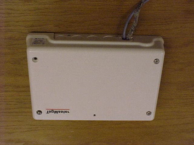
M39LRXX
Jul 26, 2006RFID Communicator
Equipment Class
FDS - Part 15 Field Disturbance Sensor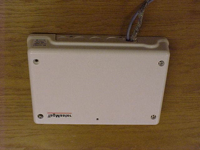
M39S15XX
Oct 16, 2003RFID Reader
Equipment Class
FDS - Part 15 Field Disturbance Sensor