M39S15XXRFID Reader
Tagmaster AB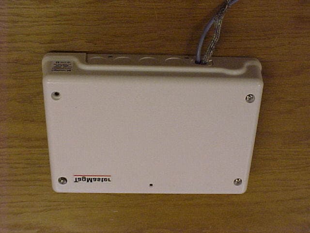
Click to zoom
Application Details
- Equipment Class
- FDS - Part 15 Field Disturbance Sensor
- Date of Grant
- Oct 16, 2003
- Application Purpose
- Original Equipment
- Date of Application
- Oct 16, 2003
- Equipment Note
- RFID Reader
- Frequency Range
- 2435.50000000 - 2464.50000000
- Company
- Tagmaster AB
- Country
- Sweden
Documents & Files
Document Text
Text extracted from the exhibit documents filed with the FCC. Open a document above to read the original.
Users Manual
TagMaster AB TagMaster AB TagMaster HW Installation Guide Manual issue 03 2 Disclaimer The information in this document is subject to change without notice. While the information contained herein is assumed to be accurate, TagMaster AB assumes no responsibility for any errors or omissions. Copyright The copyright of this document is and will remain ours. No part of this document may be reproduced or transmitted in any form or by means, electronic or mechanical, for any purpose, without the express written permission of TagMaster AB. FCC ID: M39S15XX This device complies with part 15 of the FCC Rules. Operation is subject to the following two conditions: (1) This device may not cause harmful interference, and (2) This device must accept any interference received, including interference that may cause undesired operation. NOTE: This equipment has been tested and found to comply with the limits for a Class A digital device, pursuant to part 15 of the FCC Rules. These limits are designed to provide reasonable protection against harmful interference when the equipment is operated in a commercial environment. This equipment generates, uses, and can radiate radio frequency energy and, if not installed and used in accordance with the instruction manual, may cause harmful interference to radio communications. Operation of this equipment in a residential area is likely to cause harmful interference in which case the user will be required to correct the interference at his own expense. Caution Information to user. Changes or modifications not expressly approved by the party responsible for compliance could void the user’s authority to operate the equipment. Reg. No. 510278 TagMaster AB Electrum 410 S-164 40 KISTA Sweden Tel: +46-8-632 19 50, Fax: +46-8-750 53 62 Email: [email protected], Web: http://www.tagmaster.com TagMaster AB HW Installation Guide ABOUT THIS DOCUMENT Manual issue 03 3 TABLE OF CONTENTS 1 ABOUT THIS DOCUMENT ...................................................................................... 5 1.1 Introduction ......................................................................................................... 5 1.2 Audience.............................................................................................................. 5 1.3 Definitions ........................................................................................................... 6 1.4 References ........................................................................................................... 6 1.5 Revisions ............................................................................................................. 6 2 SAFETY INSTRUCTIONS ........................................................................................ 7 2.1 General ................................................................................................................ 7 2.2 Installation ........................................................................................................... 8 3 SYSTEM COMPONENTS ......................................................................................... 9 3.1 Communicators.................................................................................................... 9 3.2 ID Tags ................................................................................................................ 9 4 ENVIRONMENTAL CONSIDERATIONS ............................................................. 10 4.1 General .............................................................................................................. 10 4.2 Electromagnetic immunity ................................................................................ 10 4.3 Temperature....................................................................................................... 10 4.3.1 Communicators.......................................................................................... 10 4.3.2 Tags ........................................................................................................... 10 5 MECHANICAL INSTALLATION .......................................................................... 11 5.1 General .............................................................................................................. 11 5.2 Communicators.................................................................................................. 11 5.2.1 Mounting ................................................................................................... 11 5.2.2 Cables ........................................................................................................ 11 5.3 ID-Tags.............................................................................................................. 12 5.4 Accessories ........................................................................................................ 12 5.5 Typical installations .......................................................................................... 13 5.5.1 Single lane identification........................................................................... 13 5.5.2 Multi lane identification ............................................................................ 13 5.5.3 How to handle and mount the tag.............................................................. 13 6 ELECTRICAL INSTALLATION............................................................................. 14 6.1 General .............................................................................................................. 14 6.2 Connection diagrams ......................................................................................... 16 6.2.1 Single Communicator connection using port A for RS232C .................... 16 6.2.2 Single Communicator connection using port B for RS232C .................... 16 6.2.3 Direct Communicator multipoint connection using port B for 2-Wire RS485 17 6.2.4 Digital I/O connections (e…
Text truncated - open the document above for the full version.
Users Manual
TagMaster AB TagMaster AB TagMaster S1566 Heavy Duty HW Installation Guide Manual issue 01 TagMaster AB HW Installation Guide TABLE OF CONTENTS Manual issue 01 2 Disclaimer The information in this document is subject to change without notice. While the information contained herein is assumed to be accurate, TagMaster AB assumes no responsibility for any errors or omissions. Copyright The copyright of this document is and will remain ours. No part of this document may be reproduced or transmitted in any form or by means, electronic or mechanical, for any purpose, without the express written permission of TagMaster AB. FCC ID: M39S15XX This device complies with part 15 of the FCC Rules. Operation is subject to the following two conditions: (1) This device may not cause harmful interference, and (2) This device must accept any interference received, including interference that may cause undesired operation. NOTE: This equipment has been tested and found to comply with the limits for a Class A digital device, pursuant to part 15 of the FCC Rules. These limits are designed to provide reasonable protection against harmful interference when the equipment is operated in a commercial environment. This equipment generates, uses, and can radiate radio frequency energy and, if not installed and used in accordance with the instruction manual, may cause harmful interference to radio communications. Operation of this equipment in a residential area is likely to cause harmful interference in which case the user will be required to correct the interference at his own expense. Caution Information to user. Changes or modifications not expressly approved by the party responsible for compliance could void the user’s authority to operate the equipment. Reg. No. 03-074 TagMaster AB Electrum 410 S-164 40 KISTA Sweden Tel: +46-8-632 19 50, Fax: +46-8-750 53 62 Email: [email protected] Web: http://www.tagmaster.com TagMaster AB HW Installation Guide TABLE OF CONTENTS Manual issue 01 3 1 TABLE OF CONTENTS 1 TABLE OF CONTENTS...................................................................................................... 3 2 REVISIONS ........................................................................................................................... 5 3 ASSOCIATED DOCUMENTATION ................................................................................. 5 4 INTRODUCTION ................................................................................................................. 6 4.1 Audience.......................................................................................................................... 6 4.2 System Block Diagram.................................................................................................... 7 4.3 Definitions ....................................................................................................................... 8 4.4 References ....................................................................................................................... 8 5 SAFETY NOTICE ................................................................................................................ 9 5.1 General ............................................................................................................................ 9 5.2 Specific warning and caution statements are used throughout this manual. ................. 10 5.3 Installation ..................................................................................................................... 10 6 SYSTEM COMPONENTS................................................................................................. 11 6.1 Communicators ............................................................................................................. 11 6.2 ID Tags .......................................................................................................................... 11 7 ENVIRONMENTAL CONSIDERATIONS ..................................................................... 12 7.1 General .......................................................................................................................... 12 7.2 Electromagnetic immunity ............................................................................................ 12 8 ELECTRICAL REQUIREMENTS................................................................................... 13 8.1 Temperature .................................................................................................................. 13 8.1.1 Communicators ..................................................................................................... 13 8.1.2 Tags ....................................................................................................................... 13 8.2 Supply Voltage .............................................................................................................. 13 8.3 Radio Interface .............................................................................................................. 13 9 MECHANICAL INSTALLATION ................................................................................... 15 9.1 General .......................................................................................................................... 15 9.2 Readers .......................................................................................................................... 15 9.2.1 Mounting ............................................................................................................... 15 9.2.2 Connecting Cable recommendation ...................................................................... 16 9.3 ID-Tags.......................................................................................................................... 17 10 ELECTRICAL CONNECTIONS.................................................................................. 18 11 EARTHING REQUIREMENTS .....…
Text truncated - open the document above for the full version.
Block Diagram
Processor XTAL 9,8304MHz DTMF XTAL 3,5795MHz PLL XTAL 12,8MHz CPU-BOARD RF-BOARD Transponder XTAL 32,768KHz 2,45GHz TAGMASTER AB BLOCK DIAGRAM
Cover Letter(s)
From: Roland Gubisch ES-Box Sent: Thursday, October 09, 2003 1:17 PM To: Monica Roos ES-STO Cc: Danielle Fontaine ES-Box Subject: RE: Application review of TagMaster FCC ID: M39S15XX Monica, Thank you for your reply. I have reviewed your comments and note the following: ADMINISTRATIVE 1) The stated text in the User Manual and Installation Guide does not refer to "changes or modifications voiding the user's authority..." The phrase given in 15.21, or something similar, should be added. 2) The PCB photos you reference were not attached. Please re-send. TECHNICAL 1) This is accepted. 2) It is not clear from the user manual that the host computer is used for configuration only, but it is reasonable and acceptable. However, there are also relay and open collector outputs to actuate external alarms or counters. Wires do not appear to have been connected to these I/O ports during testing, as required by ANSI C63.4:2001 clause 6.1.3. Please comment. 3) Thank you for the manual/guide references. Neither document prohibits the connection of the DC supply to the AC mains, so AC conducted emissions should be measured with a representative commercial AC adaptor. If both internal DC/DC power supplies are identical, only one needs to be tested wit the AC adaptor. Regards, Roland -----Original Message----- From: Monica Roos ES-STO Sent: Thursday, October 09, 2003 9:40 AM To: Roland Gubisch ES-Box Cc: Danielle Fontaine ES-Box Subject: SV: Application review of TagMaster FCC ID: M39S15XX Hi Roland, Please find our comments to you noted items: Administative 1) Please see page 7 in the manual 51027803 [TagMaster HW Installation Guide] for S1500 and page 9 in 03-074 01 S1566 User Manual for S1566. The text describes that all service and handling shall be done by specially trained personal etc. Are you satisfied with the stated text or do Tagmaster need to include more? 2) See enclosed internal photos 3) The FRN number for Tagmaster AB is 009609439 (you asked for the number i an other e- mail sent 15 Sept. 2003) Technical 1) The customer is aware of this policy. 2) The RS-232 and RS-485 ports are only service ports. 3) Regarding the AC conducted emission measurement we have questions for you. Please see page 5 in the manual 51027803 [TagMaster HW Installation Guide] for S1500 and page 7 in 03-074 01 S1566 User Manual for S1566 for pictures of the use of the products. The S1566 will be powered from different souces due to the way it is used. The S1500 is powered from a power supply (24 VDC) according to the picture in the Installation guide for S1500. Do we need to performed the AC conducted emission measurement on both products or is it enough if we perform the test S1500 using a typical power supply. Since we need to perform some kind of retesting due to the last item above a quick answer from you is appreciated. Have a nice day! Vänliga hälsningar / Best regards Monica Roos -----Ursprungligt meddelande----- Från: Roland Gubisch ES-Box Skickat: den 15 september 2003 20:44 Till: Monica Roos ES-STO Kopia: Danielle Fontaine ES-Box Ämne: Application review of TagMaster FCC ID: M39S15XX Monica, Review of this application for certification is complete, and the following items are noted: ADMINISTRATIVE 1) It is required in the user manual to include a statement conforming to 15.21: "The users manual or instruction manual...shall caution the user that changes or modifications not expressly approved by the party responsible for compliance could void the user's authority to operate the equipment." I cannot find a statement similar to this in either the S1500 or S1566 manuals. Please indicate where the statement may be found, or add it accordingly. 2) Internal photos: 2.1033(b)(7) requires a photo for both sides of each PCB. It is not apparent that internal photos provided for S1500 or S1566 comply. Please comment. TECHNICAL 1) Please note the FCC policy regarding Field Disturbance Sensor (FDS) tag readers: "Data transfer is possible only with FDS systems using passive tags and only if the data transfer function is ancillary to the primary purpose of a FDS system which is the detection of the presence of people or objects." The TagMaster equipment appears to satisfy this definition, in that it behaves as a motion or presence detector whether or not any data transfer occurs. The applicant should be aware of this policy, and may wish to comment. 2) Test set-up, test report section 3.3: there is no mention of the RS-232 or RS-485 communication connection which appears to be essential to the operation of this card reader, nor any other signal or I/O ports. ANSI C63.4 calls for one port of each type to be populated for the purpose of emissions testing. Please comment. 3) AC conducted emissions data appears to be absent. Please note Part 15 section 15.207(c) requires for intentional radiators that: "Devices that include, or make provisions for, the use of battery chargers which permit operating while charging, AC adapters or battery eliminators or that connect to the AC power line indirectly, obtaining their power through another device which is connected to the AC power lines, shall be tested to demonstrate compliance with the conducted limits." Unless it can be shown that this device will never be connected to the AC mains with an adaptor or AC supply, conducted emissions data is needed. (An off-the-shelf AC adapter should be used.) Please comment. The application can proceed to certification as soon as these issues are addressed. Thank you, Roland Gubisch
External Photos
1(2) External photos Tagmaster FCC ID: M39S15XX S1500 and S1501 S1503 and S1504 2(2) S1566
ID Label/Location Info
1(2) Marking plate location, Tagmaster FCC ID: M39S15XX S1566 S1503 and S1504 2(2) S1500 and S1501
ID Label/Location Info
1(1) Marking plate S1500/S1501
ID Label/Location Info
Material / Supplice EN 1.4301 t=1 Tolerans / Tolerance ISO 2768-m Artikelbenämning / Part name Name Plate S1566/00 Behandling / Treatment Kund / Customer Konstruerad av / Designed by TOD 2003-05-05 Stycklista / Part list Ritad av / Drawn By TOD 2003-05-05 Ändringsorder / Change order TagMaster AB Granskad av / Checked by MWI 2003-05-05 Dimensions: 65 x 17 mm Godkänd av / Approved by MWI 2003-05-05 Skala / Scale 1:1 Ritnings nr / Drawing no 510421 Status 01 Blad / Sheet 1 / 1 TAGMASTER AB Manufacturer TagMaster AB Type Communicator S 1 566/00 r e v 0 1 Serial no. FCC ID: M39S15XX Power supply 12V / max. 1A 0413 2,5 2,5 60 30 0 2 2 , 7 6,5 8 11 14 18 21 24 28 0 11 16 33 65 35 Arial (11) Bold, Underlined Arial (7) Arial narrow (11) (mm) 2.7 (4x)
Internal Photos
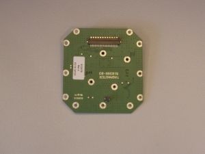
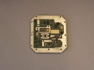
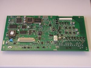
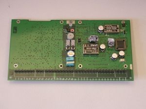
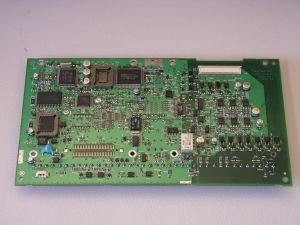
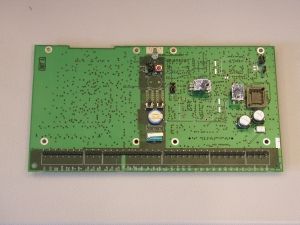
1(3) Internal photos Tagmaster FCC ID: M39S15XX S1500 S1500 2(3) S1501 S1501 3(3) S1566 See “Description of differences in the S15XX’s” for type S1503 and S1504.
Operational Description
TagMaster AB S1500 & S1501 Readers User programmable Read/Write station S1500 readers are a 2.45 GHz circular polarised read/write station for TagMaster RFID tags. Reading distance is typically up to 6 metres. The reader has 100 RF channels eliminating any interference of other nearby readers. Transmitted power and reception sen- sitivity is also adjustable with SW commands for op- timising any installation. S1500 has a movement detection function for detect- ing people and vehicles, or even smaller objects, even if not using a tag. It can determine their moving speed in approaching or retreating directions. S1500 is user programmable and has a large memory for application programs and built in database func- tions for fast, customised and efficient stand-alone op- eration. User software is downloaded and saved in EEPROM through a serial communication line. If user programming is not required, there is a ready-to-use standard application SW in the reader. A local database in EEPROM can be loaded with over 15,000 tag entries for extremely fast read-validate- activate response times. The ConfiTalk protocol is used for serial communica- tion in a polled RS485 network or point-to-point in RS232 connections. There are ConfiTalk communica- tion drivers available for DOS, Windows 3.1, 95/98/ME and NT/2000/XP with interface for C/C++, Delphi and Visual Basic. S1500 has two serial ports, a DTMF port for keypads, LED interfaces, relay, parallel I/O (emulating magcard data as an option). A control panel with a 7-segment LED display, two push buttons, a three colour LED, a buzzer and a reset button is available for local configuration and start up of test programs as installation aids. The unit can also be configured using a hand held computer or terminal connected locally. S1500 is sealed from water spray and dust. Non- corrosive materials are used in external parts. Connec- tions are made through rubber bushings, or via cable glands in a steel back plane. Jackable screw connec- tors connect the wires. Built in DC/DC converters tol- erate noisy voltages, provide low power consumption (3W) and can be set to 24 as well as 12 V DC Microwave/Antenna block Processor block I/O block DC supply RS 485 RS 232a RS 232b DTMF/LED Relay Opto I/O Radiated 2.45 GHz signal 6 m reading range Range/channel setting by SW Tag programming Movement detection at up to 5 m 3-colour LED and buzzer RS232 and 2/4 wire RS485 3 parallel in, 2 parallel out optoisolated. Relay and tamper switches EMI tolerant DC/DC conv. 24V or 12V powering User programmable C, Delphi and VB drivers Flash EEPROM database DTMF and LED interface Maintenance functions General S1500 comprises a plastic cover and a metal chas- sis for two PC boards, where the upper position carries a standard board and the lower is for an op- tion board. A rubber gasket seals the unit. The standard board includes a Processor and I/O block with analog and digital circuits, and is inte- grated with a Microwave and Antenna block. The antenna system is circular polarised and radi- ates through the front cover, with a lobe that is di- rected perpendicularly to the front surface of S1500. The lobe shape can be described as an el- lipsoid with a circular cross section, as shown in the figure below. CONFIDENT The reading and writing distances depend on the tag type and on the power and sensitivity SW set- tings. Typically, S1500 can read TagMaster tags at up to 6 m distance. See Reading/Writing range for details. When dismounting the cover, it separates from the cable inlets to conveniently operate the unit also without cover. Screw connectors are jackable and in logical groups, i.e. it is not needed to disconnect each wire to replace the electronics. J1 DTMF, LED, external tamper line J2 RS232 for terminal J3 RS232 and RS 485 for host J4 Parallel out and relay J5 Parallel in J6 DC supply To hide the cables, S1500 can be connected via cable glands in the back plane. Dual tamper switches monitor that the cover is closed. When removed, a software as well as hardware alarm is generated. For service and setup purposes there is a control panel with a 7-segment LED display, 2 control buttons, a reset button, a LED and a buzzer. There are also jumpers for RS232/485 and 12/24V selec- tion. A corrosion resistant mounting bracket that gives additional sealing for rough environments is sepa- rately available. It fits the mounting holes of S1500, and has a flexible joint for easy adjustment to different mounting angles. J1J2J3J4J5J6 8,7 236,6 120,0 23,7 Diameter of holes: 4,2 mm Reading/writing range The maximum reading or writing range is defined as the maximum distance along the radiation axis where the tag can be communicated when the tag and reader face each other and when there is free space in be- tween. The reading range depends on the tag reflectivity, the data speed (high/low), power output and sensitivity settings all resulting in R parameters for the tag and reader. Multiply these factors and the resulting reading range is found. Example: The R 1500 for S1500 is 2.7 and the R 1251, low speed for the S1251 tag is 1.5 resulting in a reading range of 2.7 * 1.5 = 4.0 meters. This assumes the high power and high sensitivity is used. If using low power and/or low sensitivity the reading range is reduced according to the following table. Range Sensitivity Power Range factor 4 HIGH HIGH 100% 3 HIGH LOW 50% 2 LOW HIGH 25% 1 LOW LOW 12% The same applies for the writing range where you mul- tiply the W factors for the tag and reader to find the resulting range. Example: The W 1500 for S1500 is 1.0 and the W 1251 for the S1251 tag is 0.5 resulting in a writing range of 1.0 * 0.5 = 0.5 meters. This assumes the high power, high sensitivity and high speed. Writing must be done at high power. The writing range is normally not affected by speed and sensitivity set- tings. Lobe width The lobe diagram shows, in a proportional scale, the approximate lobe shapes of the S1500 and S1501 read- ers. …
Text truncated - open the document above for the full version.
Operational Description
Description of model differences The S1500 and S1566 are members of an intended S15XX-series. The S1500 is the most fully-populated member of the family. S1566 Heavy Duty This reader is recently developed as a heavy-duty reader for harsh environments. It is a reduced version of the S1500, with only only RS-232 and RS-485 (2-wire) interfaces. It is based on the same hardware with the following differences. • 128 Kbyte Flash EEPROM for code only. No EEPROM database. • No 7-segment display. • No buzzer. • No hardware support for 4 wire RS-485. • 12V supply only. Standard voltage regulator instead of DC/DC converter. • No real time clock. • No option board connector.
Test Setup Photos
1(4) UPDATED TEST SET-UP PHOTOS FCC ID: M39S15XX Semi-anechoic shielded chamber (30 – 1000 MHz), type S1500 Bluetooth anechoic shielded chamber (1 – 26 GHz), type S1500 2(4) Conducted disturbance voltage 0,150-30 MHz, type S1500 Conducted disturbance voltage 0,150-30 MHz, type S1500 3(4) Semi-anechoic shielded chamber (30 – 1000 MHz), type S1566 Bluetooth anechoic shielded chamber (1 – 13 GHz), type S1566 4(4) Conducted disturbance voltage 0,150-30 MHz, type S1566 Conducted disturbance voltage 0,150-30 MHz, type S1566
Contact Information
Applicant
Johan Franzen(Chief Technical Officer)
Technical Contact
Non-Technical Contact
TagMaster ABThomas Oden
[email protected]46 8 632 19 64
Test Firm
Intertek SEMKO ABNiklas Bostrom
Technical Specifications
| # | Rule Parts | Frequency Range | Power Output |
|---|---|---|---|
| 1 | 15.245 | 2.44 GHz - 2.46 GHz | - |
Other Applications from Tagmaster AB
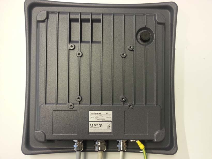
M39XTXX
Mar 30, 2014RFID reader
Equipment Class
DXT - Part 15 Low Power Transceiver, Rx Verified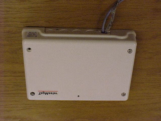
M39LRXX
Jul 26, 2006RFID Communicator
Equipment Class
FDS - Part 15 Field Disturbance Sensor