M45054064R/C TRANSMITTER
Estes-Cox Corp. d/b/a Estes Industries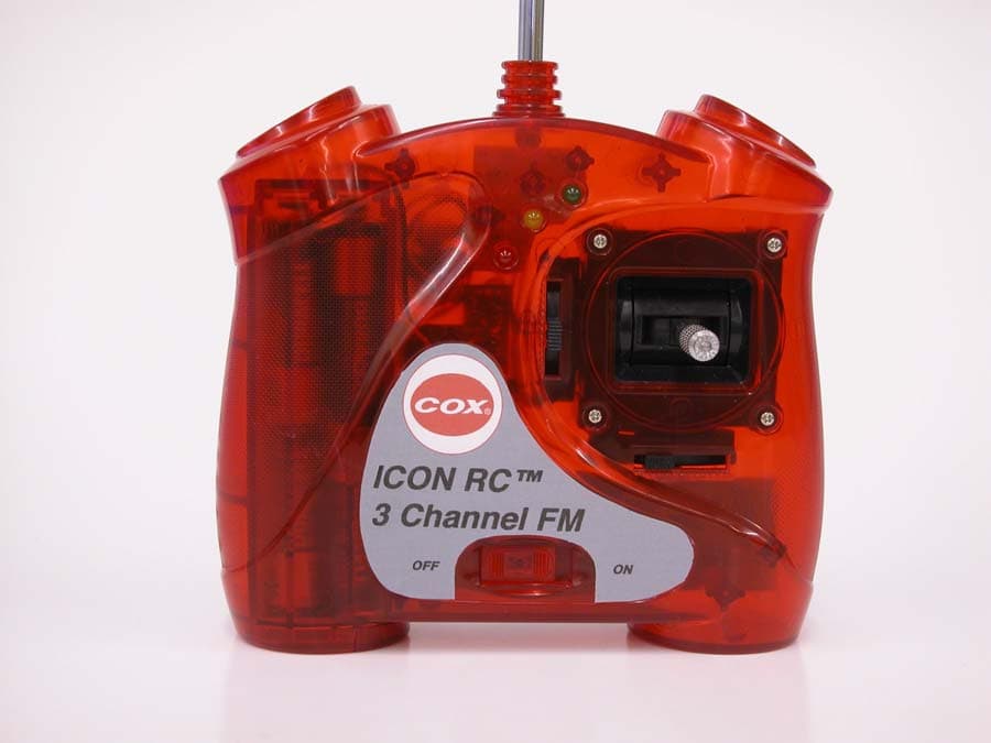
Click to zoom
Application Details
- Equipment Class
- TNB - Licensed Non-Broadcast Station Transmitter
- Date of Grant
- Nov 15, 2005
- Application Purpose
- Original Equipment
- Date of Application
- Nov 15, 2005
- Equipment Note
- R/C TRANSMITTER
- Frequency Range
- 72.00000000 - 73.00000000
- Country
- United States
Documents & Files

Document Text
Text extracted from the exhibit documents filed with the FCC. Open a document above to read the original.
Users Manual
FEATURES: • 3 channel single stick proportional FM transmitter • 3 channel, single conversion FM receiver with 10 amp ESC and BEC • Linear proportional 3rd channel lever • Servo reverse on Ch 1 and Ch 2 • “V” tail switch • Alkaline or NiCad operation • NiCad charge jack COX Hobby Distributors 1295 H St. Penrose, CO 81240 Printed in China V isit us at www .coxmodels.com ©Copyright 2005 Cox Corporation. All rights reserved. (9-05) PN 054138 Cox® One Year Limited Warranty Cox will repair or replace factory defects for one year from date of purchase. This warranty specifically does not cover crash damage or abuse! If you find a defect, or need replacement parts, please contact Cox Customer Service - at 877-269-9162 and let us know the date of purchase, order number, and reason for the return. We will promptly issue a Return Merchandise Authorization (RMA)number and give you instructions for the return. Unauthorized returns are not accepted and will be refused unless the RMA number that we issue is clearly marked on the shipping label of the return. We will assist all of our customers with fast and prompt customer service in the event of a manufacturing defect. If you return a defective part, send only the part with your purchase receipt, or other adequate proof of purchase to the Cox Customer Service Department,1295 H Street, Penrose, CO 81240 and Cox will repair or replace it if judged to be factory defective. There will be an additional handling charge if you send the whole model. This warranty applies only if the product is operated by an adult or with adult supervision and in compliance with assembly and operating instructions provided with each model. Cox assumes no liability except for the exclusive remedy of repair or replacement of parts as specified above. Cox shall not be liable for consequential or incidental damages. Some states do not allow the exclusion of incidental or consequential damages so the above limi- tation may not apply to you. This warranty gives you specific legal rights and you may also have other rights, which vary from state to state. Instruction Manual Transmitter Crystal Location Servo Reversing Switches NiCad Charge Jack Location S ystem Features Transmitter Receiver - ESC Servos Transmitter Setup Control Stick Length Installing the Antenna Battery Installation Power LED’s “V” Tail Mixing Servo Reversing Switches NiCad Charge Jack Location Transmitter Crystal Location Warranty System Features Table of Contents Transmitter - front view. Your Cox ICON RC 3 channel FM transmitter has been designed for comfort and a positive feeling of control. From the stylish and ergonomical curvature of the case to the conveniently placed, precision molded 2 axis gimbal, the Cox ICONRC™transmitter is meant to fit in your hand and provide the control authority you’d expect from an industry leader. OFF/ON Switch Power LED’s Tx Antenna Ch 2 Trim Ch 1 Trim 2 Servo reversing is a useful feature if the installation of your servos does not allow for the correct movement relative to the control stick input. To adjust, use a small screwdriver and flip the switch in the direction opposite the current setting and note the direction of movement of the control surface. There is no servo reversing for the 3rd channel. If you should choose to replace the 8 AA Alkaline batteries with rechargeable NiCads, the Cox ICON RC™ transmitter has a charge jack located on the bottom rear of the transmitter case. Make sure that the charger and batteries are suitable for this application. Do not charge non-rechargeable batteries. WARNING:Any adjustment(s) to your RC transmitter or replacement of transmitter components (crystal, semiconductor, etc.. that may result in modifying the power, range or frequency of your transmitter is a violation of FCC regulation and voids your authority to operate the transmitter . If you require a dif fer - ent operational frequency, please return the transmitter and receiver to Cox Hobbies for professional replacement and tuning. 7 “V” Tail Mixing 63 “V” tail mixing is the electronic coupling of the rudder and elevator to the 2 axis control stick. Since a “V” tail airplane requires input from both “ruddervators” for coordinated turns, the transmitter handles all of the electronic mixing of Ch 1 and Ch 2. The switch is either on or off. To turn on, use a small screwdriver and slide the switch toward the ON position. Controlling the up and down, right and left movement of a “V” tailed airplane is a little different than found on a cruciform (conventional rudder/elevator) model. Please refer to the images (as seen from the rear of the model) and directions below to properly set up your “V” tail equipped model. If required, use the servo reverse switches to get the correct direction of each control surface. If that fails to correct the problem, it may be necessary to reroute your control linkages. UPUP UP UP DOWN DOWNDOWN DOWN Airplane pitch nose UP- both ruddervators move UP. Airplane pitch nose DOWN both ruddervators move DOWN. Airplane RIGHT TURN - left ruddervator moves UP, right ruddervator moves DOWN. Airplane LEFT TURN - right ruddervator moves UP, left ruddervator moves DOWN. Receiver The COX ICON RC™ 3 channel 2 in 1 receiver is a single conversion, highly selective, light weight FM design with several sophisticated features. In addition to the 2 servo, 3 pin servo plug, the ICON RC 2-in-1 receiver features a built-in Battery Elimination Circuit (BEC), that supplies a safe 5V to your servos using a 6 cell (7.2V) battery pack. The ICON RC 2 in 1 receiver also has an Electronic Speed Control (ESC), that allows a full range of power settings to the flight motor . The high-current MOSFET motor driver is capable of supplying up to 10A of continuous motor current. In addition, the ICON 2 in 1 receiver includes a voltage sense circuit that automatically shuts off the motor when the battery pack has dropped to approximately 0.9V per cell. This allows a safe margin of remaining…
Text truncated - open the document above for the full version.
External Photos
ESTES-COX CORP. FCC ID: M45054064 EXTERNAL PHOTOS
ID Label/Location Info
Notes on The COX ‘ICON’ Transmitter FCC Label Product M45054064 Please note the attached image of the label. The label is printed on a self-adhesive backed brushed foil material. The printing color is black. The black printed frame measures 16mm (0.63”) X 40mm (1.57”). The final cut size of the label is 17mm (0.67”) X 41mm (1.61”). The label is applied after transmitter assembly and tuning to the bottom of the molded case housing.
Internal Photos
ESTES-COX CORP. FCC ID: M45054064 INTERNAL PHOTOS
Operational Description
Technical Description of The COX ‘ICON’ Transmitter Product M45054064 The COX ICON transmitter is a frequency shift modulated digital proportional design intended for use in the 72MHz model radio control band. Under previously established rules of operation, it is intended for controlling model aircraft only. It is designed for use on any of the fixed 50 channels within the 72.0MHz to 73.0MHz band. The transmitter circuitry consists of four primary sections. These include the MCU digital encoder, the FSK modulator, the RF section, and the antenna matching and harmonic trap circuitry. The antenna for the unit is a collapsible 7-section type, 1.1 meter in length. Eight 1.5V AA alkaline batteries for a total of 12 volts power the transmitter circuitry. A 5-volt regulator maintains voltage stability for all circuitry with the exception of the RF power amplifier. In production, the oscillator crystal is permanently affixed and not removable per FCC regulations. All circuitry is mounted to a single-sided printed circuit board which is mounted inside a hand- held molded plastic housing. The removable antenna is mounted to, and extends through an opening molded into the top of the molded plastic housing. A two-axis gimbaled control stick is mounted to the right of center of the face of the molded housing. The control stick provides user input commands to the MCU encoder with the rotation of two potentiometers. A third control input potentiometer is located in the back of the molded housed to the left of center. These locations are chosen for best ergonomic control inputs from the model flyer. Three battery condition LEDs are located near the center and top of the face of the molded housing. The ON/OFF switch is located near the center and bottom face of the housing. The non-removable crystal, and three function slide switches are mounted in the back of the housing near the bottom. The removable battery holder installs from the bottom of the housing and is held in place using a molded latch. The COX ‘ICON’ transmitter is a 3-Channel unit, offering three different control functions for the model flyer to control his aircraft. The three are typically elevator, ailerons, and throttle. In operation, the control input potentiometers vary the spacing between four information modulation pulses. The nominal spacing for all three channels is designed to range from 1.0ms to 2.0ms, with 1.5ms as the neutral position. A microprocessor with a crystal-controlled clock maintains accuracy for the pulses. The four information pulses are a nominal 300us in width, and are passed to the FSK modulator. The FSK modulator varies the forward voltage of a varicap diode. The varicap diode in turn varies the oscillation frequency of the RF oscillator circuitry by 3kHz. A fundamental crystal is the active component that provides the basic frequency. To achieve the final 72MHz frequency at the RF power amplifier, this frequency is multiplied by five. The RF power amplifier increases output power to be input to the antenna matching circuit. This circuit also provides harmonic trapping. The RF level is then fed to a base-loaded 1.1 meter long collapsible antenna.
Parts List/Tune Up Info
Bill of Material List ELECTRONIC COMPONENTS COX ICON TRANSMITTER PRODUCT M45054064 Used Part Type Designator ==== ========= ==================== 1 ANT1 3 0 R21 R22 R23 1 0.22uH L1 1 1.2K R20 1 1.5K R13 2 100P C18 C19 1 100uF/25V C34 1 102K VR2 2 102P C25 C7 2 103P C21 C33 2 104P C31 C36 4 10K R19 R24 R25 VR3 1 10uH L2 1 12V BT1 1 14.xxxMHZ XL1 1 16M XL2 1 1N4004 D4 1 1P C15 2 2.4K R12 R5 2 20P C26 C27 2 22 R10 R14 1 220K R17 1 222J C24 3 2694 T3 T4 T5 3 2R2 R3 R4 R7 2 2SC1923 Q2 Q3 1 2SC4735 Q1 3 3.3K R26 R27 R28 1 330uF/10V C32 4 333P C11 C12 C17 C6 3 334P C28 C29 C30 1 33P C2 1 390 R6 4 39P C10 C14 C16 C4 1 470P C23 1 47P C5 1 56 R11 1 56P C13 3 5K VR1 VR4 VR5 1 6.2V DZ3 1 6.8V DZ2 2 680 R16 R2 1 68P C3 1 7P C1A 1 9014(L6) Q4 1 DS-220 J1 2 HDR04S T1 T2 1 ISV113 D1 3 LED LED1 LED2 LED3 1 LW78L05 U2 1 SN8P2711A U1 1 SS-12F08 SW1 3 SS-22F17 SW2 SW3 SW4
Parts List/Tune Up Info
Tuning Procedure For COX ICON FM Transmitter Operating In the 72-73MHz Model Aircraft Frequency Band The Transmitter Please note that there are two specific areas of interest on the schematic titled COX HOBBIES ICON TRANSMITTER M45054064 having to do with the tuning of this transmitter. 1. The variable resistors VR2 and VR3 associated with transistor Q4 control the width of the frequency modulation for the oscillator Q3. 2. Tuned coils T2 through T5 are used to optimize and tune the transmitter to the specific operating frequency, while tuned coil T1 and its associated components form a harmonic trap. After final assembly, the transmitter is prepared for tuning by temporarily placing a ‘fake’ plastic case back onto the unit, installing the antenna, and installing a battery holder with 8 fresh alkaline batteries. The ‘fake’ case back has holes drilled in it corresponding to the five tuned coils. This allows the technician tuning the transmitter to grasp it for hand capacitance while inserting a ceramic tuning wand through the holes to adjust the coils. The removable case back also allows access to the modulation circuitry during alignment. When the tuning procedure is complete the ‘fake’ case back is replaced with a non-drilled production piece and screwed in place. The Alignment Equipment The tuning procedure for this transmitter is carried out within a screen room. The alignment equipment includes the following; 1. Frequency Counter 2. Spectrum Analyzer 3. FM/AM Modulation Meter 4. FM/AM Signal Generator (reference if needed) 5. High Frequency Oscilloscope Note that the frequency counter connected to the high frequency oscilloscope to observe all transmitter frequencies and frequency changes during alignment. Measurements are done by way of RF proximity link. The spectrum analyzer is set for split-screen operation to show the primary levels for the 72-73MHz frequencies, and the second 144-145MHz harmonic. The Tuning and Alignment Procedure Once the ‘fake’ case back and battery pack is installed in the transmitter, the telescoping antenna is fully extended, and the unit is switched on. 1. Grasping the transmitter with one hand, tune coils T5, T4, T3, and T2 for maximum RF level for the assigned frequency. 2. Coil T1 is then tuned for minimum second harmonic 144-145MHz power level. 3. Steps #1 and #2 are repeated three times in rapid succession. 4. Modulation control transistor Q4 is then shunted off. 5. The FM/AM modulation meter is then connected to the antenna. 6. Variable resistor VR3 is then adjusted for the primary 72-73MHz operation frequency. 7. Transistor Q4 is then shunted to the on position. 8. Variable resistor VR2 is then adjusted for a frequency shift from the primary operating frequency of –3KHz. 9. The shunt for transistor Q4 is then removed. 10. Normal frequency shift operation for the design from the encoder circuitry is then viewed on the modulation meter as the last tuning procedure. 11. The transmitter is removed from the alignment environment, the ‘fake’ case back, and the battery supply are removed. The correct production case back is then installed with four screws.
Schematics
123456 A B C D 654321 D C B A Title NumberRevisionSize B Date:7-Oct-2005 Sheet of File:C:\Present Projects\..\COX ICON TRANSMITTER M45054064.SCHDrawn By: R3 2R2 L2 10uH C4 39P C6 333P C5 47P R2 680 C2 33P C3 68P C17 333P C11 333P R10 22 C10 39P R11 56 C12 333P R13 1.5K R12 2.4K R14 22 R24 10K R25 10K R16 680 R17 220K C13 56P C14 39P C21 103P C23 470P C18 100P C19 100P D1 ISV113 C33 103P R4 2R2 R7 2R2 R19 10K R20 1.2K R21 0 R23 0 R22 0 C31 104P R5 2.4K ANT1 BT1 12V R6 390 C7 102P C15 1P C16 39P C25 102P J1 DS-220 VDD 1 XIN 2 XOU 3 RST 4 P5.3 5 TX-DA 6 P-H 7 HK 8 AN0 9 AN1 10 AN2 11 AN3 12 AN4 13 V S S 1 4 U1 SN8P2711A C26 20P C27 20P C28 334P C29 334P C30 334P R26 3.3K R27 3.3K R28 3.3K VR2 102K 6 4 1 2 3 T4 2694 6 4 1 2 3 T3 2694 64 123 T2 HDR04S VR3 10K VR1 5K VR5 5K VR4 5K 6 4 1 2 3 T5 2694 64 123 T1 HDR04S Vin 3 G N D 2 Vout 1 U2 LW78L05 Q3 2SC1923 Q4 9014(L6) Q2 2SC1923 3 2 1 Q1 2SC4735 1 2 3 SW1 SS-12F08 2 1 3 SW2A SS-22F17 5 4 6 SW2B SS-22F17 2 1 3 SW3A SS-22F17 5 4 6 SW3B SS-22F17 2 1 3 SW4A SS-22F17 LED1 LED LED2 LED LED3 LED C34 100uF/25V C32 330uF/10V XL1 14.xxxMHZ D4 1N4004 XL2 16M DZ2 6.8V DZ3 6.2V C24 222J +12V +5V L1 0.22uH C1A 7P Min ON OFF C36 104P CH2 CH1 TO Left or Right To Up or Down 1.1M To Front COX HOBBIES ICON TRANSMITTER M45054064 SCH V100505 Mike Dorffler PDF created with pdfFactory Pro trial version www.pdffactory.com
Test Report
TIMCO ENGINEERING INC. 849 NW State Road 45 Newberry, Florida 32669 http://www.timcoengr.com 888.472.2424 F 352.472.2030 email: [email protected] APPLICANT: ESTES-COX CORP. FCC ID: M45054064 Test Report Product Name: REMOTE CONTROL TRANSMITTER FCC ID: M45054064 Applicant: ESTES-COX CORP. 1295 H STREET P.O. BOX 227 PENROSE COLORADO 81240 USA Date Receipt: 11/7/2005 Date Tested: 11/7/2005 REPORT #: E\ESTES-COX_\2146UT55\2146UT55TestReport.doc COVER SHEET TIMCO ENGINEERING INC. 849 NW State Road 45 Newberry, Florida 32669 http://www.timcoengr.com 888.472.2424 F 352.472.2030 email: [email protected] APPLICANT: ESTES-COX CORP. FCC ID: M45054064 TABLE OF CONTENTS LIST TEST REPORT: PAGE 1............GENERAL INFORMATION & TECHNICAL DESCRIPTION PAGE 2............TECHNICAL DESCRIPTION CONTINUED RF POWER OUTPUT PAGE 3............MODULATION CHARACTERISTICS AUDIO FREQUENCY RESPONSE OCCUPIED BANDWIDTH PAGE 4............OCCUPIED BANDWIDTH PLOT PAGE 5............FIELD STRENGTH OF SPURIOUS EMISSION PAGE 6............METHOD OF MEASURING RADIATED SPURIOUS EMISSIONS PAGE 7............FREQUENCY STABILITY PAGE 8............TEST EQUIPMENT LIST EXHIBITS INCLUDING: BLOCK DIAGRAM SCHEMATIC PARTS LIST USERS MANUAL LABEL SAMPLE LABEL LOCATION EXTERNAL PHOTOGRAPHS INTERNAL PHOTOGRAPHS ALIGNMENT PROCEDURE OPERATIONAL DESCRIPTION TEST SET UP PHOTOGRAPH REPORT #: U:\E\ESTES-COX_\2146UT5\2146UT5TestReport.doc TABLE OF CONTENTS TIMCO ENGINEERING INC. 849 NW State Road 45 Newberry, Florida 32669 http://www.timcoengr.com 888.472.2424 F 352.472.2030 email: [email protected] APPLICANT: ESTES-COX CORP. FCC ID: M45054064 GENERAL INFORMATION 2.1033(c)(1)(2) ESTES-COX CORP. will sell the FCC ID: M45054064 Radio Control transmitter in quantity, for use PART 95 SUBPART C. ESTES-COX CORP. 1295 H STREET P.O. BOX 227 PENROSE COLORADO 81240 2.1033(c)(3) Instruction manual is included in the exhibits. 2.1033 (4) Type of Emission: 8K0F1D 95.631 (b)(5) Bn = 2M + 2DK M = 4,800 Bits per second D = 1600 Hz (Peak Deviation) K = 1 Bn = 2(4.8/2) + 2(1600)(1) =4.8K + 3.2K =8.0k ALLOWED AUTHORIZED BANDWIDTH = 8.00 kHz. 95.631 (b) Authorized Bandwidth 8 kHz for RC Transmitter 2.1033(c)(6) Frequency Range: 72.0 – 73.00 MHz 95.623 (a)(7) Power Range and Controls: There are NO user Power controls. (8) Function of each electron tube or semiconductor device or other active circuit device are included in the exhibits (9) Maximum Output Power Rating: 0.164 W ERP. (10) DC Voltages and Current into Final Amplifier: FINAL AMPLIFIER ONLY Vce = 12.0 VDC Ice = 0.039 A. Pin = 0.5 W 2.1033(c)(11) Tune-up procedure. The tune-up procedure is included in the exhibits. REPORT #: U:\E\ESTES-COX_\2146UT5\2146UT5TestReport.doc Page 1 of 8 TIMCO ENGINEERING INC. 849 NW State Road 45 Newberry, Florida 32669 http://www.timcoengr.com 888.472.2424 F 352.472.2030 email: [email protected] APPLICANT: ESTES-COX CORP. FCC ID: M45054064 2.1033(c)(12) Complete Circuit Diagrams: The circuit diagram are included in the exhibits. (13) Description of all circuitry and devices provided for determining and stabilizing frequency is given in the exhibits. 2.1033(c)(14) The Equipment identification is shown in the exhibits. 2.1033(c)(15) Photographs of the equipment are shown in the exhibits. 2.1033(c)(16) Equipment employing Digital modulation. N/A. 2.1033(c)(17) The data required by 2.1046-2.1057 follows; 2.1046 RF power is measured by the ERP METHOD. There are no provisions to limit the power. With a nominal battery voltage of 12.0 VDC, and the transmitter properly adjusted the RF output measures: Po = 0.164 Watts RADIATED SUBSTITUTION 2.1046 RF power output. SIGNAL GENERATOR DIPOLE ANTENNA TRANSMITTER UNDER TEST WITH INTERNAL ANTENNA 3.0 METERS HP SPECTRUM ANALYZER TUNED, CALIBRATED ANTENNA, WHICH MAY BE RAISED FROM 1 TO 4 METERS ABOVE GROUND AND CHANGED IN POLARIZATION Equipment placed 80 cm. above ground on a rotatable platform. REPORT #: U:\E\ESTES-COX_\2146UT5\2146UT5TestReport.doc Page 2 of 8 TIMCO ENGINEERING INC. 849 NW State Road 45 Newberry, Florida 32669 http://www.timcoengr.com 888.472.2424 F 352.472.2030 email: [email protected] APPLICANT: ESTES-COX CORP. FCC ID: M45054064 2.1047 Modulation characteristics: AUDIO FREQUENCY RESPONSE The Voice is NOT allowed in this band. 2.1049 Occupied bandwidth: 95.635 (b) (1) At least 25dB on any frequency removed from the center of the authorized bandwidth by more than 50% up to and including 100% of the authorized bandwidth. (3) At least 55 dB on any frequency removed from the center of the authorized bandwidth by more than 125% up to and including 250% of the authorized bandwidth. (7) At least 43+ 10 log10 (T) dB on any frequency removed from the center of the authorized bandwidth by more than 250%. (10) At least 45 dB on any frequency removed form the center of the authorized bandwidth by more than 100% up to and including 125% of the authorized bandwidth. (11) At least 55% dB on any frequency removed form the center of the authorized bandwidth by more than 125% up to and including 250%of the authorized bandwidth. (12) At least 56+ 10 log10 (T)dB on any frequency removed from the center of the authorized bandwidth by more than 250%. REPORT #: U:\E\ESTES-COX_\2146UT5\2146UT5TestReport.doc Page 3 of 8 TIMCO ENGINEERING INC. 849 NW State Road 45 Newberry, Florida 32669 http://www.timcoengr.com 888.472.2424 F 352.472.2030 email: [email protected] APPLICANT: ESTES-COX CORP. FCC ID: M45054064 Radiotelephone Transmitter with Modulation Limiter Test Procedure Diagram OCCUPIED BANDWIDTH MEASUREMENT 50 ohm RESISTIVE WATTMETER TRANSMITTER UNDERTEST AUDIO OSCILLATOR REPORT #: U:\E\ESTES-COX_\2146UT5\2146UT5TestReport.doc Page 4 of 8 TIMCO ENGINEERING INC. 849 NW State Road 45 Newberry, Florida 32669 http://www.timcoengr.com 888.472.2424 F 352.472.2030 email: [email protected] APPLICANT: ESTES-COX CORP. FCC ID: M45054064 OCCUPIED BANDWIDTH PLOT REPORT #: U:\E\ESTES-COX_\2146UT5\2146UT5TestReport.doc Page 5 of 8 TIMCO ENGINEERING INC. 849 NW State…
Text truncated - open the document above for the full version.
Contact Information
Applicant
Mary Roberts(Technical Services)
Test Firm
Timco Engineering, Inc.S Sanders
Technical Specifications
| # | Rule Parts | Frequency Range | Power Output | Emission | Tolerance |
|---|---|---|---|---|---|
| 1 | 95C | 72 MHz - 73 MHz | 164.00 mW | 8K0F1D | 20.0000000000 ppm |
Other Applications from Estes-Cox Corp. d/b/a Estes Industries

M45-5103
Dec 03, 2015PROTO N
Equipment Class
DSS - Part 15 Spread Spectrum Transmitter
M45-4611
Jul 27, 20142.4G remote controller
Equipment Class
DXX - Part 15 Low Power Communication Device Transmitter
M45-46066V1
Dec 29, 2013Proto X/Syncro
Equipment Class
DXX - Part 15 Low Power Communication Device Transmitter
M45-46066
Sep 29, 2013Proto X
Equipment Class
DXX - Part 15 Low Power Communication Device Transmitter
M45-45503
Jul 24, 20132.4GHz two-channel radio transmitter for use with radio-controlled model airplanes
Equipment Class
DXX - Part 15 Low Power Communication Device Transmitter