M4D-902FM Stereo Transmitter Module
Cardio Theater Holdings Inc
Click to zoom
Application Details
- Equipment Class
- DXX - Part 15 Low Power Communication Device Transmitter
- Date of Grant
- Oct 07, 2003
- Application Purpose
- Original Equipment
- Date of Application
- Oct 07, 2003
- Equipment Note
- FM Stereo Transmitter Module
- Frequency Range
- 905.05000000 - 923.67000000
- Company
- Cardio Theater Holdings Inc
- Country
- United States
Documents & Files
Document Text
Text extracted from the exhibit documents filed with the FCC. Open a document above to read the original.
Users Manual
Wireless Entertainment System Model xTV-9T Transmitter Model xTV-9R Receiver Operation Manual 21420-D NW Nicholas Ct #12 Hillsboro, Oregon Sales (800) 227-3461 Fax (503) 645-9036 www.cardiotheater.com www.enercise.tv FCC NOTICE This device complies with Part 15 of the FCC Rules. Operation is subject to the following two conditions: (1) This device may not cause harmful terference, and (2) this device must accept any interference received ding interference that may cause undesired operat in, incluion. TABLE OF CONTENTS Step 1: Setting Transmitter Number USA & Canada Mode Page 1 Australia Mode Page 2 Step 2: Connecting Transmitter to TV Page 3 Step 3: Installing Receiver Page 4 Step 4: Programming Receiver Page 5 Specifications Page 6 Warranty / Technical Support Page 7-8 STEP 1: SETTING TRANSMITTER NUMBER / USA & CANADA MODE Simply set the left and right dials on the rear of the transmitter to the corresponding numbers below. Example: For Transmitter #1 set left dial to “0” and right dial to “1” Transmitter Left Dial Right Dial #1 0 1 #2 0 2 #3 0 3 #4 0 4 #5 0 5 #6 0 6 #7 0 7 #8 0 8 #9 0 9 #10 1 0 #11 1 1 #12 1 2 #13 1 3 #14 1 4 #15 1 5 #16 1 6 #17 1 7 #18 1 8 #19 1 9 #20 2 0 #21 2 1 #22 2 2 #23 2 3 #24 2 4 #25 2 5 #26 2 6 #27 2 7 #28 2 8 #29 2 9 #30 3 0 #31 3 1 #32 3 2 1 STEP 1: SETTING TRANSMITTER NUMBER / AUSTRALIA MODE Warning! End user is responsible for following the number chart below for use in Australia. Setting Transmitter dials to any other number than the ones detailed in the chart below may result in fines and or additional punishment by local authorities. Simply set the left and right dials on the rear of the transmitter to the corresponding numbers below. Transmitter Left Dial Right Dial #1 0 3 #2 0 4 #3 0 5 #4 1 1 #5 1 2 #6 1 3 #7 1 4 #8 1 5 #9 1 6 #10 2 6 #11 2 7 #12 2 8 #13 2 9 #14 3 0 #15 3 1 #16 3 2 2 STEP 2: CONNECTING TRANSMITTER TO TELEVISION Important: Television with “Audio Output” jack required. 1. Connect provided patch cable into Left & Right Audio Output Jack on rear of TV. 2. Plug other end of patch cable into the Left & Right Audio Input jack on rear of transmitter. 3. Plug provided AC adapter into 110 AC outlet. 4. Turn TV Speakers OFF via TV menu function. 5. Turn TV volume up at least 50%. 6. Adjust audio level control so red “Peak” light blinks on and off. Caution: Turning audio level to high will cause sound distortion 7. Plug heaphones into xTV receiver. Match sound level of each TV by adjusting volume of each individual TV. 8. Place corresponding number sign under each TV CONNECTING THE xTV-9T TRANSMITTER TO MUSIC COMPONENT: 1. Connect provided patch cable into Left & Right Audio Output Jack on rear of music component and follow steps 2 through 8 above. 3 STEP 3: INSTALLING RECEIVER Mounting Receiver The Enercise xTV Receiver is designed to mount to any make or model of cardio equipment. 1. Insert two nylon wire ties (provided) through the holes in the mounting bracket on the rear of the Enercise xTV Receiver. 2. Wrap wire ties tightly around the bar so the receiver does not rotate. ΝΟΤΕ : Do not place receiver where it would interfere with the cardio unit controls or display panel. The xTV Receiver mounting bracket may be removed with pliers and mounted with Super Lock Velcro to any flat surface. Powering Receiver Power the xTV Receiver one of two ways: 1. C-Safe Cable: Most cardio manufacturers offer C-Safe compatibility. Connect the Ultra Seal C-Safe cable to the C-Safe port located on cardio unit. (Refer to the manufacturer to locate C-Safe port on cardio unit). Note: Many CV manufacturers offer C-Safe retrofit kits for older models. Contact your CV manufacturer for availability. 2. 9 Volt AC Adapter: In the event that C-Safe is not available on the cardio unit, use the optional Ultra Seal 9 Volt AC adapter. A standard 110AC outlet is required near the cardio unit. Ultra Seal Connector: The exclusive Enercise Ultra Seal power connector, found on both Enercise C- Safe cables and Enercise 9 Volt AC Adapters, prevents sweat or cleaning products, from entering the unit. 1. Insert the connector on the rear of the xTV-R and press firmly around the connector hood to make a complete seal. 2. To disconnect, press tab on bottom side of connector and release. 4 STEP 4: PROGRAMMING xTV-9R RECEIVER This function enables the receiver to program the exact amount of transmitters and number them accordingly. Enercise Auto Program Mode (When Using Enercise Transmitters): 1. To activate program mode, press Volume UP and Down buttons simultaneously for 3 seconds. The number 1 with a decimal point on the left side will pop up in display window 2. Press the EQ button to begin Scanning. Scanning will take about 15 seconds. 3. When Scanning is completed, press channel Up and Down buttons to confirm all transmitters have been programmed. Cardio Theater™ LCS Program Mode (When Using LCS Transmitters): 1. Press Volume "UP & DOWN" simultaneously for 3 seconds. The number 1 With a decimal point on the left side will pop up in display window 2. Press Channel 'UP" button for 2 seconds to select #2. 3. Press "EQ" button to begin Scanning. Scanning will take about 25 seconds. BroadcastVision™ 900 Program Mode (When Using BV900 16 Channel Transmitters): 1. Press Volume "UP & DOWN" simultaneously for 3 seconds. The number 1 with a decimal point on the left side will pop up in display window. 2. Press Channel 'UP" button for 2 seconds to select #3. 3. Press "EQ" button to begin Scanning. Scanning will take about 15 seconds. NOTE: BroadcastVision transmitters must be set to stereo/music mode. Manual Program Mode (To Add or Delete Channels Manually) 1. Perform Auto Program scan. Wait for Auto Program sequence to complete. 2. Press Channel UP and Down buttons simultaneously for 3 seconds. The number 1 with a decimal point on the left side will pop up in display window. 3. To activate any channel, press Channel Up or Down button to select desired channel. Press the EQ button to activate…
Text truncated - open the document above for the full version.
Attestation Statements
1 Scott McCutchan To: [email protected] Cc: Ruby Hall Subject: FCC ID: M4D-902 Mr. Madlangbayan, In order for processing of this application (FCC ID: M4D-902) to continue, the following issue will have to be addressed: 1) Please indicate the type of modulation utilized for this device. 2) Please indicate compliance with the voltage variation requirements contained in Section 15.31(e) of the FCC rules. The item(s) indicated above must be submitted before processing can continueon the above referenced application. Failure to provide the requestedinformation within 60 days of the original e-mail date may result in application dismissal and forfeiture of the filing fee. Also, please note that partial responses increase processing time and should not be submitted. Please upload responses and/or exhibits to the electronic filing website. Your correspondence number is M4D-902-1. If you have any questions, feel free to contact me. Best regards, Scott McCutchan Operations Manager Compatible Electronics TCB (714) 579-1489 fax (714) 579-1850 http://www.celectronics.com Correspondence by Project Project Number: 1065484512 Correspondence Number Memo M4D-902-1 Mr. McCutchen, Please see page two of the product description regarding the type of Modulation utilized. For the volatage requirements, please see the additional exhibits. Thank You kindly, Joey Madlangbayan
Test Report
FCC ID: M4D-902 Report Number: A30917F1 2337 TROUTDALE DRIVE, AGOURA, CALIFORNIA, 91301 • PH: (818) 597-0600 FX: (818) 597-1187 Page 1 of 17 FCC PART 15, SUBPART C TEST REPORT for 902-928 MHz FM STEREO TRANSMITTER MODULE Model: xTV-9T FCC ID: M4D-902 Prepared for CARDIO THEATER HOLDINGS, INC 21420-D NW NICHOLAS COURT #12 HILLSBORO OR, 97124 Prepared by: _____________________ ANDRE D. KHAN Approved by: ____________________ RUBY A. HALL COMPATIBLE ELECTRONICS INC. 2337 TROUTDALE DRIVE AGOURA, CALIFORNIA 91301 (818) 597-0600 DATE: SEPTEMBER 22, 2003 REPORT APPENDICES TOTAL BODY A B C D E PAGES 17 2 2 2 13 21 57 This report shall not be reproduced except in full, without the written approval of Compatible Electronics. FCC ID: M4D-902 Report Number: A30917F1 2337 TROUTDALE DRIVE, AGOURA, CALIFORNIA, 91301 • PH: (818) 597-0600 FX: (818) 597-1187 Page 2 of 17 TABLE OF CONTENTS Section / Title PAGE GENERAL REPORT SUMMARY 4 SUMMARY OF TEST RESULTS 4 1. PURPOSE 5 2. ADMINISTRATIVE DATA 6 2.1 Location of Testing 6 2.2 Traceability Statement 6 2.3 Cognizant Personnel 6 2.4 Date Test Sample was Received 6 2.5 Disposition of the Test Sample 6 2.6 Abbreviations and Acronyms 6 3. APPLICABLE DOCUMENTS 7 4. Description of Test Configuration 8 4.1 Description of Test Configuration - EMI 8 4.1.1 Photograph of Test Configuration - EMI 8 4.1.2 Cable Construction and Termination 9 5. LISTS OF EUT, ACCESSORIES AND TEST EQUIPMENT 10 5.1 EUT and Accessory List 10 5.2 EMI Test Equipment 11 6. TEST SITE DESCRIPTION 12 6.1 Test Facility Description 12 6.2 EUT Mounting, Bonding and Grounding 12 7. Test Procedures 13 7.1 RF Emissions 13 7.1.1 Conducted Emissions Test 13 7.1.2 Radiated Emissions Test 14 7.1.3 RF Emissions Test Results 15 RADIATED EMISSION – BAND EDGE 16 8. CONCLUSIONS 17 FCC ID: M4D-902 Report Number: A30917F1 2337 TROUTDALE DRIVE, AGOURA, CALIFORNIA, 91301 • PH: (818) 597-0600 FX: (818) 597-1187 Page 3 of 17 LIST OF APPENDICES APPENDIX TITLE A Laboratory Accreditations B Modifications to the EUT C Additional Models Covered Under This Report D Diagrams, Charts and Photos • Test Setup Diagrams • Antenna and Amplifier Gain Factors • Radiated and Conducted Emissions Photos E Data Sheets LIST OF FIGURES FIGURE TITLE 1 Conducted Emissions Test Setup 2 Plot Map And Layout of Test Site FCC ID: M4D-902 Report Number: A30917F1 2337 TROUTDALE DRIVE, AGOURA, CALIFORNIA, 91301 • PH: (818) 597-0600 FX: (818) 597-1187 Page 4 of 17 GENERAL REPORT SUMMARY This electromagnetic emission report is generated by Compatible Electronics Inc., which is an independent testing and consulting firm. The test report is based on testing performed by Compatible Electronics personnel according to the measurement procedures described in the test specifications given below and in the "Test Procedures" section of this report. The measurement data and conclusions appearing herein relate only to the sample tested and this report may not be reproduced in any form except in full, without the written permission of Compatible Electronics. This report must not be used to claim product endorsement by NVLAP, NIST or any other agency of the U.S. Government. Device Tested: 902-928 MHz FM Stereo Transmitter Module Model: xTV-9T SN: US-2 Product Description: This is an FM Stereo Transmitter Module. Modifications: The EUT was not modified during the testing. Manufacturer: Cardio Theater Holdings, Inc. 21420-D NW Nicholas Court #12 Hillsboro, OR 97124 Test Dates: September 17 & 22, 2003 Test Specifications: EMI requirements FCC CFR Title 47, Part 15 Subpart C Test Procedure: ANSI C63.4: 2001. Test Deviations: The test procedure was not deviated from during the testing. SUMMARY OF TEST RESULTS TEST DESCRIPTION RESULTS 1 Conducted RF Emissions, 150 kHz - 30 MHz. Complies with the limits of FCC CFR Title 47, Part 15 Subpart C 15.207. Highest Reading in relation to spec. limit: 37.19 dBuV @ 1.148 MHz (*u c = 0.27dB) 2 Radiated RF Emissions, 10 kHz - 10 GHz. Complies with the limits of FCC CFR Title 47, Part 15 Subpart C 15.205, 15.209 and 15.249. Highest Reading in relation to spec. limit: 91.20 dBuV @ 923.67 MHz (*u c = 2.91dB) FCC ID: M4D-902 Report Number: A30917F1 2337 TROUTDALE DRIVE, AGOURA, CALIFORNIA, 91301 • PH: (818) 597-0600 FX: (818) 597-1187 Page 5 of 17 1. PURPOSE This document is a qualification test report based on the Electromagnetic Interference (EMI) tests performed on the 902-928 MHz FM Stereo Transmitter Module Model: xTV-9T. The EMI measurements were performed according to the measurement procedure described in ANSI C63.4: 2001. The tests were performed in order to determine whether the electromagnetic emissions from the equipment under test, referred to as EUT hereafter, are within the specification limits defined in FCC CFR Title 47, Subpart C 15.205, 15.207, 15.209 and 15.249. FCC ID: M4D-902 Report Number: A30917F1 2337 TROUTDALE DRIVE, AGOURA, CALIFORNIA, 91301 • PH: (818) 597-0600 FX: (818) 597-1187 Page 6 of 17 2. ADMINISTRATIVE DATA 2.1 Location of Testing The EMI tests described herein were performed at the test facility of Compatible Electronics, 2337 Troutdale Drive, Agoura, California 91301. 2.2 Traceability Statement The calibration certificates of all test equipment used during the test are on file at the location of the test. The calibration is traceable to the National Institute of Standards and Technology (NIST). 2.3 Cognizant Personnel Cardio Theater Holdings, Inc. Tony Garcia Executive Vice President Compatible Electronics Inc. Andre D. Khan Test Technician Ruby A. Hall Lab Manager 2.4 Date Test Sample was Received The test sample was received on September 17, 2003. 2.5 Disposition of the Test Sample The test sample remains at Compatible Electronics, Inc. 2.6 Abbreviations and Acronyms The following abbreviations and acronyms may be used in this document. RF Radio Frequency EMI Electromagnetic Interference EUT Equipment Under Test P/N Part Number S/N Serial Number HP Hewlett Packard ITE Information Technology Equip…
Text truncated - open the document above for the full version.
Test Report
FCC ID: M4D-902 Report Number: A30917F1 2337 TROUTDALE DRIVE, AGOURA, CALIFORNIA, 91301 • PH: (818) 597-0600 FX: (818) 597-1187 Page 4 of 17 GENERAL REPORT SUMMARY This electromagnetic emission report is generated by Compatible Electronics Inc., which is an independent testing and consulting firm. The test report is based on testing performed by Compatible Electronics personnel according to the measurement procedures described in the test specifications given below and in the "Test Procedures" section of this report. The measurement data and conclusions appearing herein relate only to the sample tested and this report may not be reproduced in any form except in full, without the written permission of Compatible Electronics. This report must not be used to claim product endorsement by NVLAP, NIST or any other agency of the U.S. Government. Device Tested: 902-928 MHz FM Stereo Transmitter Module Model: xTV-9T SN: US-2 Product Description: This is an FM Stereo Transmitter Module. Modifications: The EUT was not modified during the testing. Manufacturer: Cardio Theater Holdings, Inc. 21420-D NW Nicholas Court #12 Hillsboro, OR 97124 Test Dates: September 17 & 22, 2003 Test Specifications: EMI requirements FCC CFR Title 47, Part 15 Subpart C Test Procedure: ANSI C63.4: 2001. Test Deviations: The test procedure was not deviated from during the testing. SUMMARY OF TEST RESULTS TEST DESCRIPTION RESULTS 1 Conducted RF Emissions, 150 kHz - 30 MHz. Complies with the limits of FCC CFR Title 47, Part 15 Subpart C 15.207. Highest Reading in relation to spec. limit: 37.19 dBuV @ 1.148 MHz (*u c = 0.27dB) 2 Radiated RF Emissions, 10 kHz - 10 GHz. Complies with the limits of FCC CFR Title 47, Part 15 Subpart C 15.205, 15.209 and 15.249 and the requirements of 15.31(e) Highest Reading in relation to spec. limit: 91.20 dBuV @ 923.67 MHz (*u c = 2.91dB)
Test Report
FCC ID: M4D-902 Report Number: A30917F1 2337 TROUTDALE DRIVE, AGOURA, CALIFORNIA, 91301 • PH: (818) 597-0600 FX: (818) 597-1187 Page 17 of 17 8. CONCLUSIONS The 902-928 MHz FM Stereo Transmitter Module Model: xTV-9T meets all of the requirements of the FCC CFR, Title 47, Part 15 Subpart A, Section 15.31(e), Subpart C 15.205, 15.207, 15.209 and 15.249.
Contact Information
Applicant
Rick Hoagland(General Manager)
Technical Contact
Compatible ElectronicsJoey Madlangbayan
[email protected]818-597-0600
2337 Troutdale Drive · Agoura, California · United States
Test Firm
Compatible ElectronicsRuby Hall
Technical Specifications
| # | Rule Parts | Frequency Range | Power Output |
|---|---|---|---|
| 1 | 15C | 905.05 MHz - 923.67 MHz | - |
Other Applications from Cardio Theater Holdings Inc
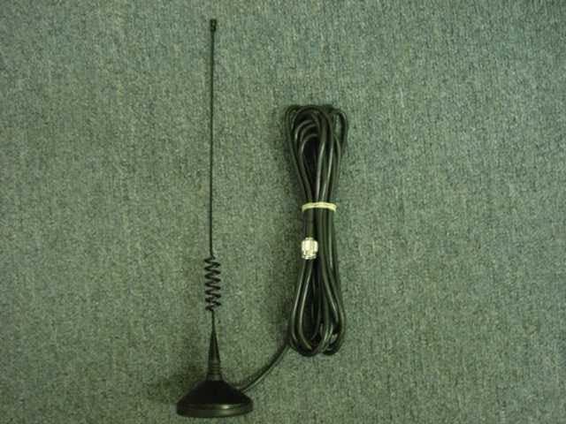
M4D1010
Mar 12, 2000Stereo TX
Equipment Class
DXX - Part 15 Low Power Communication Device Transmitter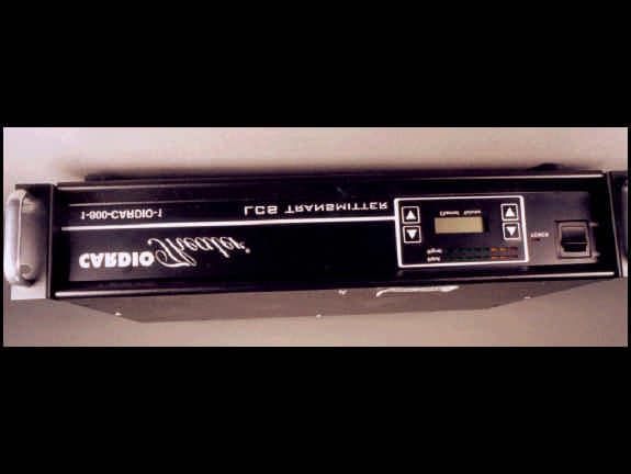
M4D0413
Mar 05, 2000Stereo TX
Equipment Class
DXX - Part 15 Low Power Communication Device Transmitter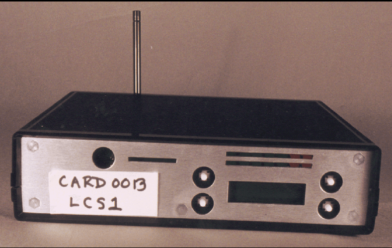
M4D0318
Feb 15, 2000Audio TX
Equipment Class
DXX - Part 15 Low Power Communication Device TransmitterM4D0656
Feb 19, 1997Audio Transmitter
Equipment Class
DXX - Part 15 Low Power Communication Device TransmitterM4D257
Nov 24, 1996Audio Transmitter
Equipment Class
DXX - Part 15 Low Power Communication Device Transmitter