M4D1010Stereo TX
Cardio Theater Holdings Inc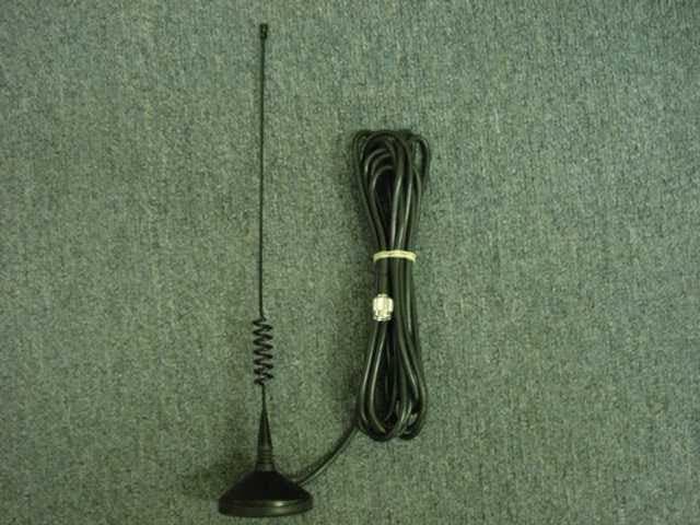
Click to zoom
Application Details
- Equipment Class
- DXX - Part 15 Low Power Communication Device Transmitter
- Date of Grant
- Mar 12, 2000
- Application Purpose
- Original Equipment
- Date of Application
- Mar 05, 2000
- Equipment Note
- Stereo TX
- Frequency Range
- 903.60000000 - 926.20000000
- Company
- Cardio Theater Holdings Inc
- Country
- United States
Documents & Files
Document Text
Text extracted from the exhibit documents filed with the FCC. Open a document above to read the original.
Users Manual
INSTRUCTION MANUAL LCS TX – 4 Channel Transmitter LCS1 – Single Channel Transmitter Cardio Theater Inc. Service 1-800-776-6695 Sales 1-800-CARDIO-1 1Introduction CONGRATULATIONS on your choice of this product. Its superior sound reproduction will provide enjoyment and entertainment. We appreciate your patronage and take pride in the quality components our company produces. Please read this manual before you install and operate the system. This manual will acquaint you with operating features and system-connection considerations. Retain this manual for future reference. For your records Record the serial number found on the back of the LCS-TX – 4 Channel Transmitter or LCS1 – Single Channel Transmitter. Refer to the serial number whenever you call your dealer for information or service. Serial Number: Unpacking Unpack the units carefully and secure all parts so that none are misplaced. Examine the units for possible damage. If any damage is noticed, notify your dealer immediately. If the system was shipped to you, notify the shipping company without delay. Only the person or company receiving the goods can file a claim against the carrier for shipping damage. We recommend that you retain the original carton and packing materials should you need to transport the system in the future. Contents Before You Begin....................................................................................................................................2 Important Safeguards.............................................................................................................................3 Suggestions for Installation.....................................................................................................................5 Controls and Indicators...........................................................................................................................6 System Connections.................................................................................................................................9 Receiver Configurations........................................................................................................................10 Attaching LCS Receivers......................................................................................................................11 LCS-TX – 4 Channel Transmitter Setup..............................................................................................12 LCS-1 – Single Channel Transmitter Setup.........................................................................................13 LCS Transmitter/Satellite/Cable Configuration..................................................................................14 LCS Transmitter/TV Setup..................................................................................................................15 LCS Receiver Setup..............................................................................................................................16 Specifications.........................................................................................................................................18 Before You Begin2 • Please ensure that you have all of the required equipment before disposing of any packing materials. LCS-TX – 4 Channel Transmitter LCS1 – Single Channel Transmitter LCS RECEIVER Quantity as ordered POWER CORD Quantity – one per transmitter WIRETIES Quantity two per receiver POWER ADAPTER (a.k.a.: wallbug) Quantity – As ordered (two wireties per wallbug) ANTENNA Quantity – one per transmitter CSAFE CABLE Quantity – one per each Cardio Theater Ready piece of equipment. 3Important Safeguards Please read all of the safeguards before operating this unit. Follow all warnings placed on the unit and adhere to the operating and use instructions. Retain this manual for future reference. 1.Power sources - Connect the unit to a power source only of the type described in the operating instructions or as marked on the appliance. 2.Power-cord protection - Route all power-supply cords so that they are not walked on or pinched by items placed upon or against them. 3. Grounding - Take precautions so that the grounding or polarization means of the unit are not defeated. 4.Ventilation - Position the unit so that its location does not interfere with ventilation. To maintain good ventilation, do not put items on or over the unit. Do not use the unit on a cushioned surface that may block the ventilation openings. 5. Water and moisture - Do not locate the unit near water. 6. Temperature - The unit may not function properly if used at extreme temperatures. The ideal temperature is 41oF (5 o C) to 87 o F (30 o C) 7.Heat - The unit should be located away from heat sources such as radiators, heat registers, stoves, etc. 8. Electric shock - Care should be taken so that objects do not fall and liquid is not spilled on the enclosure. If a metal object, such as a hairpin or a needle, comes in contact with the inside of this unit, a dangerous electric shock may result. 9.Enclosure removal - Never open the enclosure. If the internal parts are accidentally touched, a serious shock may occur. 10.Cleaning – Use a clean dry cloth. Do not use solvents such as alcohol; paint thinner, etc. to clean the unit. 11.Abnormal smell - If an abnormal smell is detected, immediately turn the power OFF and disconnect the power cord. Contact your dealer or service center. Important Safeguards - Continued4 12.Stands - Any component stand should be 14.Damage requiring service - The unit should moved with care. Quick or excessive forcebe serviced by a qualified Cardio Theater technician when: could cause the stand to overturn. A.The power cord or the plug has been damaged; B.Objects have fallen on, or liquid has been spilled into the unit; C.The unit has been exposed to rain; D.The unit does not appear to operate normally or exhibits a marked change in performance; E.The unit has been dropped or the encl…
Text truncated - open the document above for the full version.
Block Diagram
LCS FOUR CHANNEL TRANSMITTER BLOCK DIAGRAM VOLUME CONTROL STEREO MODULATOR VCO L R POWER AMPLIFIER LPF ANTENNA 38 KHZ OSC 4 MHZ REF 0SC 902-928 MHZ CONTROLSLCD DISPLAYPOWER SUPPLY 4MHZ CLOCK PROCESSOR - ADC LEVEL Σ POWER SWITCH ANTENNA RESISTANCE SENSE VCO 902-928 MHZ VOLUME CONTROL STEREO MODULATOR L R CHANNEL # 1 CHANNEL # 4
Block Diagram
LCS FOUR CHANNEL TRANSMITTER BLOCK DIAGRAM VOLUME CONTROL STEREO MODULATOR VCO L R POWER AMPLIFIER LPF ANTENNA 38 KHZ OSC 4 MHZ REF 0SC 902-928 MHZ CONTROLSLCD DISPLAYPOWER SUPPLY 4MHZ CLOCK PROCESSOR - ADC LEVEL Σ POWER SWITCH ANTENNA RESISTANCE SENSE VCO 902-928 MHZ VOLUME CONTROL STEREO MODULATOR L R CHANNEL # 1 CHANNEL # 4
ID Label/Location Info
LCS-TX, Rev. E – FCC ID Label Placement Input 1 PATENT PENDING FCC ID: M4D1010 This device complies with part 15 of the FCC rules. Operation is subject to the following two conditions: 1) This device may not cause harmful interference; And 2) This device must accept any interference received, including interference that may cause undesired operation CAUTION TO REDUCE THE RISK OF ELECTRIC SHOCK DO NOT REMOVE COVER. NO USER SERVICEABLE PARTS INSIDE. REFER SERVICE TO QUALIFIED SERVICE PERSONNEL OffOn 12Vdc 500ma
ID Label/Location Info
LCS-TX, Rev. E – FCC ID Label Placement Input 1 PATENT PENDING FCC ID: M4D1010 This device complies with part 15 of the FCC rules. Operation is subject to the following two conditions: 1) This device may not cause harmful interference; And 2) This device must accept any interference received, including interference that may cause undesired operation CAUTION TO REDUCE THE RISK OF ELECTRIC SHOCK DO NOT REMOVE COVER. NO USER SERVICEABLE PARTS INSIDE. REFER SERVICE TO QUALIFIED SERVICE PERSONNEL OffOn 12Vdc 500ma
Operational Description
LCS FOUR CHANNEL TRANSMITTER BLOCK DIAGRAM VOLUME CONTROL STEREO MODULATOR VCO L R POWER AMPLIFIER LPF ANTENNA 38 KHZ OSC 4 MHZ REF 0SC 902-928 MHZ CONTROLSLCD DISPLAYPOWER SUPPLY 4MHZ CLOCK PROCESSOR - ADC LEVEL Σ POWER SWITCH ANTENNA RESISTANCE SENSE VCO 902-928 MHZ VOLUME CONTROL STEREO MODULATOR L R CHANNEL # 1 CHANNEL # 4 LCS TRANSMITTER DESCRIPTION The transmitter is a four channel stereo FM transmitter operating in 902 - 928 Mhz frequency band. Microcontroller controls all the functions - reading the keypad, setting the volume (modulation depth), loading the synthesizers and displaying the channel number, volume settings and audio signal levels. Stereo audio signal from the audio source after the volume control circuitry goes to stereo modulator and then to synthesized VCO. Four modulated RF signals from VCO’s combined together and amplified by the power amplifier. Following the amplifier is the low pass filter which supress high order harmonics of the transmitted signal. Antenna is the modification of a resonant quarter-wavelength monopole with coax cable. The transmitter is powered by 120 VAC and is grounded by the standard three conductor power cord.
Test Report
Measurement/Technical Report Cardio Theater, Inc., LCS-TX, Rev. E FCC ID: M4D February 24, 2000 This report concerns (check one):Original Grant √__ Class II Change_____ Equipment Type: Intentional Radiator_ Deferred grant requested per 47 CFR 0.457 (d)(1)(ii)?yes_____ no__X__ If yes, defer until:______N/A______ date Cardio Theater agrees to notify the Commission by:______N/A______ date of the intended date of announcement of the product so that the grant can be issued on that date. Transition Rules Request per 15.37:yes_____ no__X__ If no, assumed Part 15, Subpart B for unintentional radiators - new 47 CFR [10-1-92] provision. Report prepared by:Northwest EMC, Inc. 22975 NW Evergreen Parkway, Suite 400 Hillsboro, OR 97124 (503) 844-4066 fax: (503) 844-3826 Report No. CARD0023 FCC ID: M4D Northwest EMC, Inc.Report No. CARD0023Page - 2 Table of Contents SectionDescriptionPage 1.0General Information3 1.1Product Description3 1.2Related Submittals/Grants4 1.3Tested System Details4 1.4Test Methodology5 1.5Test Facility5 2.0System Test Configuration6 2.1Justification6 2.2EUT Exercise Software6 2.3Special Accessories6 2.4Equipment Modifications6 Figure 2.1Configuration of Tested System7 3.0Conducted Emissions Data8 4.0Radiated Emissions Data10 4.2Field Strength Calculations12 4.3Measurement Bandwidths12 5.0Measurement Equipment13 Appendix IMeasurement Procedures14 FCC ID: M4D Northwest EMC, Inc.Report No. CARD0023Page - 3 1.0 General Information 1.1 Product Description Manufactured By............................................................................................Cardio Theater, Inc. Address............................................................21420 NW Nicholas Court, Hillsboro, OR 97124 Test Requested By:................................................................................................Rick Hoagland Model...................................................................................................................LCS-TX, Rev. E FCC ID..................................................................................................................................M4D Serial Number(s).....................................................................................................................N/A Date of Test.....................................................................................................February 24, 2000 Job Number.................................................................................................................CARD0023 The Equipment Under Test (EUT) is the Cardio Theater LCS-TX, Rev. E. The EUT is a four channel stereo FM transmitter operating in 903.6 – 926.2 MHz frequency band. A microcontroller controls all of the functions – reading the keypad, setting the volume (modulation depth), loading the synthesizers and displaying the channel number, volume settings and audio signal levels. Hardware Description: • Clocks/Oscillators Frequencies: 38 kHz, 4 MHz, 903.6-926.2 MHz • Ports: (4) Audio/Stereo Inputs, Antenna Input, Power Input • Antenna: Quarter-Wavelength Monopole, 3 dBi gain, Antenna World, Model BAS87ultra15F FCC ID: M4D Northwest EMC, Inc.Report No. CARD0023Page - 4 1.2 Related Submittals/Grants None. 1.3 Tested System Details EUT and Peripherals Item FCC ID Description and Serial No. EUTM4DCardio Theater, LCS-TX, Rev. E, Low Power Transmitter, Serial No. None. CD PlayerSony model D-171, S/N: 8010567 CD PlayerMagnavox model AZ6820, N/A: 22947140 Tape PlayerSony, model WM-EX102, S/N: 1.88541e+006 Tape PlayerSony, model WM-EX122, S/N: 767859 Cables: Item Description Audio Input1.0 meters in length. Shielded and no ferrite beads. Plastic connector. Connected from the EUT to the CD Player. Audio Input1.0 meters in length. Shielded and no ferrite beads. Plastic connector. Connected from the EUT to the CD Player. Audio Input1.0 meters in length. Shielded and no ferrite beads. Plastic connector. Connected from the EUT to the Tape Player. Audio Input1.0 meters in length. Shielded and no ferrite beads. Plastic connector. Connected from the EUT to the Tape Player. Power Input2.0 meters in length. Not shielded and no ferrite beads. AC connector. Connected from the EUT to the AC Mains. Antenna2.0 meters in length. Shielded and no ferrite beads. Metal connector. Connected from the EUT to the Antenna. FCC ID: M4D Northwest EMC, Inc.Report No. CARD0023Page - 5 1.4 Test Methodology Both conducted and radiated testing was performed according to the procedures in ANSI C63.4 (1992). Radiated testing was performed at an antenna to EUT distance of 3 meters. Please reference Appendix I for further detail on Test Methodology. 1.5 Test Facility The Open Area Test Site and conducted measurement facility used to collect the radiated and conducted data is located at Northwest EMC, Inc. 22975 NW Evergreen Parkway, Suite 400 Hillsboro, OR 97124 (503) 844-4066 Fax: 844-3826 The Open Area Test Site, and conducted measurement facility used to collect this data is located at the address shown above. This site has been fully described in a report filed and accepted by the FCC. (31040/SIT)(1300B3). It is also recognized under the National Voluntary Laboratory Accreditation Program (NVLAP Lab Code: 200059-0) for satisfactory compliance with criteria established in Title 15, Part 285 Code of Federal Regulations. Northwest EMC, Inc. is recognized under the United States Department of Commerce, National Institute of Standards and Technology, National Voluntary Laboratory Accreditation Program (NVLAP) for satisfactory compliance with criteria established in Title 15, Part 285 Code of Federal Regulations. These criteria encompass the requirements of ISO/IEC Guide 25 and the relevant requirements of ISO 9002 (ANSI/ASQC Q92-1987) as suppliers of calibration or test results. NVLAP Lab Code: 200059-0. FCC ID: M4D Northwest EMC, Inc.Report No. CARD0023Page - 6 2.0 System Test Configuration 2.1 Justification The EUT was configured to simulate typical use. Cable…
Text truncated - open the document above for the full version.
Test Setup Photos
Radiated Emission Test Set-up Photos Conducted Emission Test Set-up Photos
Contact Information
Applicant
Rick Hoagland(General Manager)
Technical Contact
Northwest EMC, Inc.Gregory V Kiemel
[email protected]503-844-4066
22975 NW Evergreen Parkway, Suite 400 · Hillsboro, Oregon · United States
Non-Technical Contact
Northwest EMC, Inc.Brenda M Wood
[email protected]503-844-4066
Test Firm
Northwest EMC, Inc.Greg Kiemel
Technical Specifications
| # | Rule Parts | Frequency Range | Power Output |
|---|---|---|---|
| 1 | 15C | 903.6 MHz - 926.2 MHz | - |
Other Applications from Cardio Theater Holdings Inc

M4D-902
Oct 07, 2003FM Stereo Transmitter Module
Equipment Class
DXX - Part 15 Low Power Communication Device Transmitter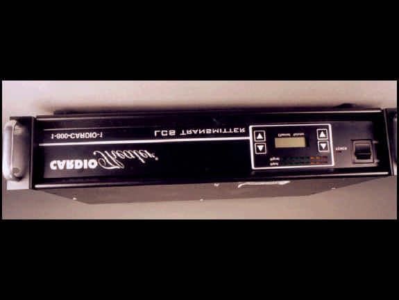
M4D0413
Mar 05, 2000Stereo TX
Equipment Class
DXX - Part 15 Low Power Communication Device Transmitter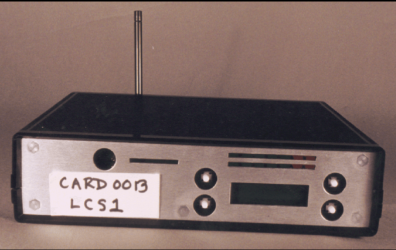
M4D0318
Feb 15, 2000Audio TX
Equipment Class
DXX - Part 15 Low Power Communication Device TransmitterM4D0656
Feb 19, 1997Audio Transmitter
Equipment Class
DXX - Part 15 Low Power Communication Device TransmitterM4D257
Nov 24, 1996Audio Transmitter
Equipment Class
DXX - Part 15 Low Power Communication Device Transmitter