M5ZFDEZIOIR Field Disturbance Sensor
Mesa Laboratories, Inc.
Click to zoom
Application Details
- Equipment Class
- DSC - Part 15 Security/Remote Control Transmitter
- Date of Grant
- Aug 15, 2007
- Application Purpose
- Original Equipment
- Date of Application
- Aug 15, 2007
- Equipment Note
- IR Field Disturbance Sensor
- Frequency Range
- 418.00000000 - 418.00000000
- Company
- Mesa Laboratories, Inc.
- Country
- United States
Documents & Files
Document Text
Text extracted from the exhibit documents filed with the FCC. Open a document above to read the original.
Users Manual
FCC ID: M5ZFDEZIO Point Six, Inc. Installation and Operation Instructions Wireless IR Field Disturbance Sensor Model FDEZIO 2 Description: The IR field disturbance sensor counts directional disturbances in its IR field and transmits packets which contain information pertaining to these counts. It is installed in locations where object counting is desired. Service Switch: Briefly pass a magnet over the service reed to activate the module. . Packet Structure: “DirectionCtr” (65/64) IDSSSSSSSSaaaaaabbbbbbCCCCKK<CR> Note: All fields are in ASCII Hex “ID” The device type field: Directional Counter has device type 65 hex. A 64 hex when in service mode. “SSSSSSSS” The MS-30 bits of these 4-bytes are the serial number of the Directional Counter. The LS-2 bits are the status flags.The meaning of the status flags are: Bit 1 Bit 0 State 00Blocked 01Okay 10Line power alarm 11Battery Alarm “aaaaaa” This 24-bit field is the direction “A” counter stored LS-byte first. Count s in Direction “A”. “bbbbbb” This 24-bit field is the direction “B” counter stored LS-byte first. Count s in Direction “B”. “CCCC” This field is the CRC-16 error check as was originally received and checked. This CRC is over the first 11 bytes of the packet starting with the device type and ending with but not including CRC-16. “KK” This field is the mod 256 sum of all the binary data values as represented by the ASCII hex values in the response but does not include the <CR>. Note: “Blocked” is when the sensor’s beam has been blocked for typically 10 seconds. Example Packet 6510732581FF0000FE0000464516 SN = 10732580; state = Okay; CountA = 255; CountB = 254 3 NOTE: This equipment has been tested and found to comply with the limits for a Class B digital device, pursuant to Part 15 of the FCC Rules. These limits are designed to provide reasonable protection against harmful interference in a residential installation. This equipment generates, uses and can radiate radio frequency energy and, if not installed and used in accordance with the instructions, may cause harmful interference to radio communications. However, there is no guarantee that interference will not occur in a particular installation. If this equipment does cause harmful interference to radio or television reception, which can be determined by turning the equipment off and on, the user is encouraged to try to correct the interference by one or more of the following measures: -- Reorient or relocate the receiving antenna. -- Increase the separation between the equipment and receiver. -- Connect the equipment into an outlet on a circuit different from that to which the receiver is connected. -- Consult the dealer or an experienced radio/TV technician for help. This device complies with Part 15 of the FCC Rules. Operation is subject to the following two conditions: (1) this device may not cause harmful interference, and (2) this device must accept any interference received, including interference that may cause undesired operation. FCC ID: M5ZFDEZIO MADE IN USA WARNING: Changes or modifications not expressly approved by the manufacturer for compliance could void the user’s authority to operate the equipment. Magnetic service switch.
Cover Letter(s)
August, 8 2007 Federal Communications Commission Equipment Approval Services re: FCC ID: M5ZFDEZIO Gentlemen: Enclosed please find the Point Six, Inc. application for FCC Certification of the Point Six Wireless IR field disturbance sensor, Model FDEZIO. The test data submitted as part of this application was prepared by dBi Corporation, 216 Hillsboro Ave., Lexington, Kentucky 40511-2105. dBi Corporation has A2LA accreditation for EMC testing, Certificate number 1985-01, valid to September 30, 2008. The facility used for radiated measurements is owned by Lexmark International, Inc. and was recognized by the Commission as meeting the requirements of section 2.948 of the Rules via a letter dated December 10, 2001, under Registration No. 949691. We submit the information in this application pursuant to the requirements of section 2.1033 and Part 15 of the Federal Communications Commission Rules and Regulations. We request that the Commission grant equipment authorization as soon as it is determined that the attached Application for Equipment Authorization is acceptable. We further request that the schematics and block diagrams of the Point Six Wireless Vibration/Motion sensor Model FDEZIO, be treated as confidential information as provided for in 47 CFR Section 0.459 (d) (2). Point Six considers this information to be a trade secret. The schematics and block diagrams are in pdf files (included with this application) and are listed as FDEZIO Sch.pdf and FDEZIO (Block-Diag).pdf respectively. Thank you in advance for your assistance. If further information is required concerning this application, please do not hesitate to contact me. Sincerely John I. Compton President, Point Six, Inc. Point Six, Inc. 2333 Alumni Park Plaza Suite 305 Lexington, Ky. 40517 859-266-3606 Fax 859-266-0542
Cover Letter(s)
Q: The cursors on the supplied 10sec separation plot may or may not be at the exact same points of the pulses (i.e from start of one to the start of next pulse or from end-to-end). How was this ensured during the measurement? At least 10sec of separation must be precisely demonstrated. A: The 10 second transmission period is a worse case boundary condition, the actual periods are always bigger. The cursors on the supplied plot were forced to 10 seconds by controlling or turning off all the variable contributions to the calculated period for the purposes of demonstrating the worse case boundary condition. I have stated that these are indeed the worse case conditions, actually having them occur in the lab without forcing them is not possible. The plots are an accurate representation of the worse case.
External Photos
FDEZIO ExteriorPhotos FDEZIO top FDEZIO right FDEZIO bottomFDEZIO left FDEZIO ExteriorPhotos FDEZIO Front FDEZIO Back
ID Label/Location Info
FDEZIO Motion Sensor Label
Internal Photos
FDEZIO interiorPhotos Interior top Interior bottom Antenna Interior top under antenna And battery
Internal Photos
FDEZIO Antenna
Operational Description
FCC ID: M5ZFDEZIO Operational description of the 418 mHz. battery operated IR field disturbance sensor. Description of the circuit functions, ground system and antenna of the IR Field Disturbance Wireless transmitter The Point Six IR field disturbance Wireless transmitter model FDEZIO is a lithium battery operated, microprocessor based, 418 MHz. transmitters that transmits vibration or motion data and a unique 30-bit serial number. The microprocessor is brought up from a power down state every 1/60 second by an internal timer in the microprocessor. The processor calculates a random number that is added to a base number resulting in a period that is always greater than 10 seconds and less than 17 seconds. When this time has expired the microprocessor gathers data from the IR counters. The microprocessor converts this information to digital data and then combines the data and with the serial number data from an onboard stored unique serial number and then transmits the entire data packet serially with a Linx Technologies TXM-418-LC-R 418 MHz. Transmitter module. The microprocessor then powers down into a quiescent state to wait for the next interrupt from the on board timer. The PC board bottom layer is a ground plane and the antenna is a 1/4-wave loop that has been etched in PC board material and placed into the ABS enclosures cover.
Test Report
dBi Corporation FCC Certification Test Report Point Six FDEZIO Wireless Sensor Report Number 07dBi010 Testing Certificate #1985.01 dBi Corporation 07dBi010 Page 2 of 20 ADMINISTRATIVE INFORMATION Historical record: Because dBi Corporation is a testing entity, and not a manufacturer, this original test report of the FDEZIO wireless sensor is being transmitted to the manufacturer, Point Six. dBi will keep a copy for its historical records and to satisfy A2LA-audit requirements. We strongly recommend archiving the unit that we tested, to facilitate answering future inquiries regarding this product. Retention of records: The FCC requires the records for a Class A or Class B product to be retained by the responsible party for at least two years after the manufacture of said product has been permanently discontinued. These records should include the original certification or verification test report, quality audit data, and the test procedures used. The European Union requires the Declaration of Conformity (DoC) and all supporting data for a product bearing the CE Marking to be retained, and available for inspection by enforcement authorities, for 10 years after placing the product on the market. Australia and New Zealand require the Declaration of Conformity, test reports, a description of the product, documentation that clearly identifies the product, and paperwork showing the product’s brand name, model number, etc. to be kept for at least five years after the product ceases to be supplied to Australia or New Zealand. Measurement uncertainties: The Lexmark Electromagnetic Compatibility Laboratory (EMC Lab) has a documented calculation of the measurement uncertainties associated with tests performed at the Lexmark site. Ongoing compliance: This report applies only to the sample tested. The manufacturer is responsibility for ensuring that the production models of this wireless sensor comply with the FCC and CE Marking requirements, and continue to comply throughout their manufacturing life. The manufacturer should check any changes to the product that could change its interference profile. A2LA approval: dBi Corporation has been accredited by the American Association for Laboratory Accreditation (A2LA) for Radiated Emissions and Conducted Emissions, Electromagnetic Interference, and Electrostatic Discharge testing. Copies of our Accreditation Certificate and Scope of Accreditation follow. The Federal Communications Commission (FCC) recognized the Lexmark site as meeting the requirements of section 2.948 of the FCC Rules in a letter dated December 10, 2001. This information is on file with the FCC under Registration No. 949691. Please note: This report may be copied as needed, as long as it is copied in its entirety. dBi Corporation 07dBi010 Page 3 of 20 dBi Corporation 07dBi010 Page 4 of 20 dBi Corporation 07dBi010 Page 5 of 20 dBi Corporation 07dBi010 Page 6 of 20 ADMINISTRATIVE DATA Manufacturer: Point Six, Inc. 2333 Alumni Park Plaza, Suite 305 Lexington, KY 40517 Appliance/Product: IR field disturbance counter Model/Type Number: FDEZIO FCC ID: M5ZFDEZIO Rating: 3.6Vdc (Lithium battery) Suppression Components: see attached sheet Measurement Equipment used: see attached sheet. Measurements According to, and Sample Unit Complies with: FCC 47 CFR Part 15-2006 Report Prepared By: John R. Barnes KS4GL, PE, NCE, NCT, ESDC Eng, ESDC Tech, PSE, SM IEEE Testing Performed by: dBi Corporation 216 Hillsboro Avenue Lexington, KY 40511-2105, USA Testing Performed on: July 29 & 31, 2007 at: Lexmark International, Inc. Development Lab. Lexington, KY 40550, USA Reviewed and Approved by: John R. Barnes KS4GL, PE, NCE, NCT, ESDC Eng, ESDC Tech, PSE, SM IEEE SIGNED_______________________________DATE__August 8, 2007__ John R. Barnes, PRESIDENT dBi Corp. dBi Corporation 07dBi010 Page 7 of 20 INFORMATION RELATING TO PRODUCT RF INTERFERENCE Appliance/Product: IR field disturbance counter Model/Type Number: FDEZIO FCC ID: M5ZFDEZIO Rating: 3.6Vdc (Lithium battery) Suppression Components: none Clock Frequencies: 8MHz and 418MHz Cables: none. Electronic Printed Circuit Boards: IR-CTR-DIRECTIONAL-418P/N P2792 Size of Product: 64mm x 51mm x 25mm high Weight of Product: 70g dBi Corporation 07dBi010 Page 8 of 20 Radiated Emissions 30-4,180 MHz Radiated Emission Standards: FCC 47 CFR Part 15-2006, using ANSI C63.4-2003; section 15.231(e) limits for 418MHz. Appliance/Product: IR field disturbance counter Model/Type Number: FDEZIO FCC ID: M5ZFDEZIO Rating: 3.6Vdc (Lithium battery) Serial Number: 70767010 Host and Other Peripherals: None Name of Test: Radiated Interference Test Procedure: ANSI C63.4-2003 Test Location: 5m semianechoic chamber Test Distance: 3m Test Instrumentation: See attached sheets Notes: Transmitting at 1 second intervals to speed up testing. Based on our experiences testing previous FCC Part 15.231(e) products, we put a calibrated 20dB attenuator right after the bi-con antenna to prevent signal compression in the preamp/receiver chain. for measurements from 30-1000MHz. We added its loss (20.194dB at 418MHz, 20.15dB at 836MHz) to the field strengths measured by the receiver in this band. We used a different antenna and preamp for measurements above 1GHz. The FCC Part 15.231(e) limits above 1GHz are lower than the FCC Class A limits above 1GHz, thus any linearity concerns had been addressed during equipment calibration. Due to software limitations, we had to measure PK+, QP, and AVE for 418MHz and its harmonics in manual mode, as follows: 1. With the equipment-under-test (EUT) upright, measure 418MHz and 836MHz in QP mode with the bi-con antenna vertical and horizontal (Lexmark’s EMC software records the azimuth and antenna elevation for the highest QP emissions). 2. Repeat step 1 with the EUT on its back. 3. Repeat step 1 with the EUT on its side. 4. Study the plots to determine which orientation of the EUT had the highest emissions in QP mode. 5. Return the EUT to this position. With the bi-con antenna…
Text truncated - open the document above for the full version.
Test Report
To Whom It May Concern: The Point Six FDEZIO IR field disturbance sensor transmits a 15-16 millisecond packet with a maximum total ON-time in any 100ms interval of 8ms. The smallest period between transmissions is 10 seconds, shown below. The packet consists of transmitter-on/transmitter-off timing that represents the serial number and data. The duty cycle is approximately 50%. The packet time can vary with serial number between 14-16 milliseconds. The Point Six wireless IR field disturbance sensor model FDEZIO has a maximum total ON-time in any 100ms interval of 8ms. The packet data is controlled by a microprocessor whose timing is based on a ceramic resonator that is very stable. The packet below (figure #2) illustrates a typical data packet, the worst case, 16 milliseconds, cannot be shown because serial number would have to be forced to make this so. Figure #1 illustrates the overall timing; a packet is sent each 10 seconds in this worst case. The battery used during the tests was new and was a standard 3.6 Volt Lithium cell. The battery is a 3.6 Volt Lithium chemistry, which has a flat discharge curve from new to about 90% used. In this application the battery requires about 3 years to discharge to the point that it cannot be used. The battery was used for no other purpose and had operated in the test unit for only a short time when the test was performed. The push button function does not alter the nature of the transmitted packet. The push button causes the next packet to be transmitted to have a different numerical data value when decoded then would otherwise be the case, indicating that the unit was being serviced. The label will be Flexcon 2 mil PM200S mylar with a Flexcon 1 mil PM100C Polyester laminate. The adhesive is permanent. John I. Compton President, Point Six, Inc. Point Six, Inc. 2333 Alumni Park Plaza Suite 305 Lexington, Ky. 40517 859-266-3606 Fax 271-0702 Figure #1 Overall timing Figure #2 Packet Timing
Test Setup Photos
FCC RADIATED-EMISSIONS TEST CONFIGURATION FDEZIO 5m SEMIANECHOIC CHAMBER LEXMARK INTERNATIONAL, LEXINGTON KY. dBi Corporation 07dBi010 Page 2 of 2 FCC OCCUPIED BANDWIDTH TEST CONFIGURATION FDEZIO 5m SEMIANECHOIC CHAMBER LEXMARK INTERNATIONAL, LEXINGTON KY.
Contact Information
Applicant
Jasmine Stone(Director of Quality)
Test Firm
dBi CorporationJohn Barnes
Technical Specifications
| # | Rule Parts | Frequency Range | Power Output |
|---|---|---|---|
| 1 | 15.231(e) | 418 MHz - 418 MHz | - |
Other Applications from Mesa Laboratories, Inc.
M5ZTMPC
Apr 23, 2012IR Point Sensor
Equipment Class
DSC - Part 15 Security/Remote Control Transmitter
M5ZP6HWSO
Mar 14, 2007Temperature Sensor
Equipment Class
DSC - Part 15 Security/Remote Control Transmitter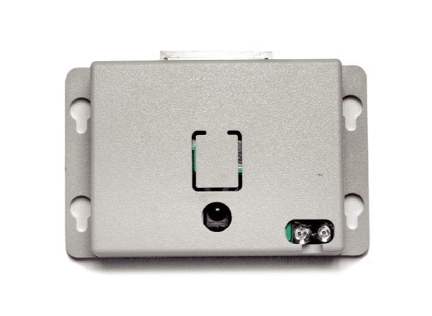
M5ZIRPROX2
Apr 18, 2006IR Proximity Counter
Equipment Class
DSC - Part 15 Security/Remote Control Transmitter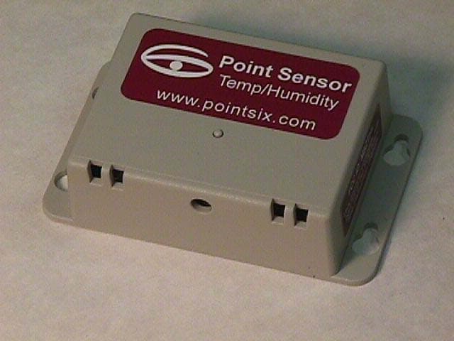
M5ZTHL
Mar 10, 2003Wireless Temperature/Humidity Sensor
Equipment Class
DSC - Part 15 Security/Remote Control Transmitter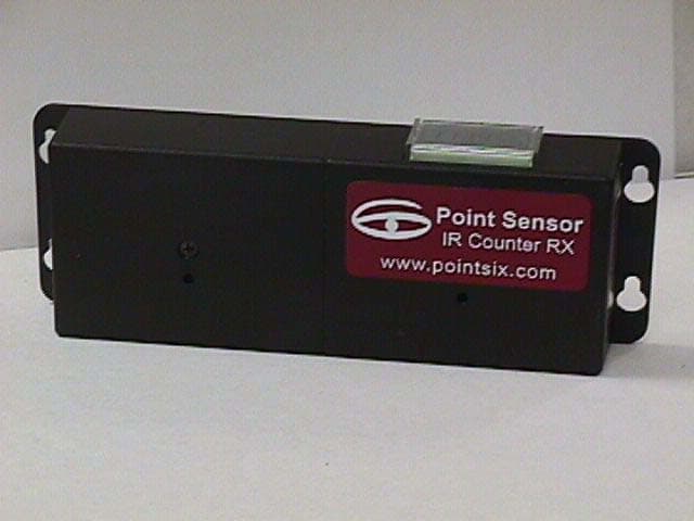
M5ZIRPC2
Mar 09, 2003IR Counter Transmitter
Equipment Class
DSC - Part 15 Security/Remote Control Transmitter