M5ZIRPROX2IR Proximity Counter
Mesa Laboratories, Inc.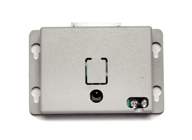
Click to zoom
Application Details
- Equipment Class
- DSC - Part 15 Security/Remote Control Transmitter
- Date of Grant
- Apr 18, 2006
- Application Purpose
- Original Equipment
- Date of Application
- Apr 18, 2006
- Equipment Note
- IR Proximity Counter
- Frequency Range
- 417.90000000 - 418.20000000
- Company
- Mesa Laboratories, Inc.
- Country
- United States
Documents & Files
Document Text
Text extracted from the exhibit documents filed with the FCC. Open a document above to read the original.
Users Manual
Point Six, Inc. 2333 Alumni Park Plaza - Lexington, KY - 40517- http://www.pointsix.com - 859-266-3606 - Fax 859-266-0702 FCC ID: M5ZIRPROX2 Installation and Operation Instructions for the IR Proximity Counter. Point Six, Inc. Wireless IR Proximity Counter Model IRPROX2 Installation and Operation Instructions Description The new IRPROX2 people counter has a battery life of >2years. The pushbutton on the sensor has the following functions: Power Down: Press and hold the button for > 8 Seconds. Test power state: Press briefly; LED comes on to indicate power down state. Power Up : Press for >2 seconds and <8 seconds, LED goes out. Transmit service packet: Briefly press while powered up. IR Program: Press and hold the button for >8 seconds while sending IR program parameter commands from IR transmitter attached to the serial port of a PC running Prox-Programmer software. When an IR command is properly received and processed the LED will flash to indicate success. This model has IR ranges of 6,4,3 and 2 feet, switch selectable. The IR programmability includes: In-beam time in ¼ second steps to 255 steps. Default: ¼ second. Out-of-beam time in ¼ second steps to 255 steps. Default: 1 second. Blocked beam time in ¼ second steps to 255 steps. Default: 16 seconds. LED flash enable/disable during count. Default: LED flash. Packet type enable/disable for automatic inclusion of the switch data in a new device type, type "09" the standard people counter is type "11" Note: IR programmed parameters are stored in EEPROM and are not lost when replacing the battery. Note: the LED flashes at other times as normal even if disabled to flash during count. Note: The packets are micro-randomized for 10 seconds +- 7 (1/4) second intervals. Point Six, Inc. 2333 Alumni Park Plaza - Lexington, KY - 40517- http://www.pointsix.com - 859-266-3606 - Fax 859-266-0702 2 Packet Description IDSSSSSSSSooooooccccccCCCCKK<CR> N ote: All fields are in ASCII Hex “ID” The device type field: “2CountRange” has device type 9 hex. A 8 hex when in service mode. “SSSSSSSS” The MS-30 bits of these 4-bytes are the serial number of the sensor. The LS-2 bits are the status flags for the open and closed limit switches. The LS bit (bit-0) is the Open switch flag and the next most significant bit (bit-1) is the Closed switch flag. For the Point Sensor IR Counter(Old) and Point Sensor IR Proximity Counter, the status bits have the following meaning: Bit 1 Bit 0 State 00Blocked 01Open 10Closed 11Error “oooooo” This 24-bit field is the Open counter stored LS-byte first. “cccccc” THE LOWER 22-BITS OF THE 24 BITS IS A DURATION COUNTER STORED LS-BYTE FIRST. THE DURATION COUNTER COUNTS THE NUMBER OF SECONDS THE BEAM IS OPEN (IN SECONDS). THE TOP 2 BITS (BITS 23 & 24) ARE USED IN INDICATE THE TYPE OF RANGE. Bit 1 Bit 0 State 00Range1 01Range2 10Range3 11Range4 “CCCC” This field is the CRC-16 error check as was originally received and checked. This CRC is over the first 11 bytes of the packet starting with the device type and ending with but not including CRC-16. “KK” This field is the mod 256 sum of all the binary data values as represented by the ASCII hex values in the response but does not include the <CR>. Point Six, Inc. 2333 Alumni Park Plaza - Lexington, KY - 40517- http://www.pointsix.com - 859-266-3606 - Fax 859-266-0702 3 In Beam : Select the desired in beam time requirement in ¼ second units to a max of 255 units. Out of Beam : Select the desired out of beam time requirement in ¼ second units to a max of 255 units. Blocked Time: Select the desired blocked time requirement in ¼ second units to a max of 255 units. Include Switch Data: Packet type enable/disable for automatic inclusion of the switch data. YES= type "09", NO=type “11” (see packed definition above). Note: changing device type will result in a changed serial number; two devices cannot be allowed to exist with identical serial numbers so when the device type is reprogrammed the serial number will be automatically changed as well. Allow LED to Flash on Count: Yes= LED will flash when people count advances. No= LED will not flash when people counter advances. IR Program: Press and hold the proximity sensor pushbutton for >8 seconds, aim the IR program transmitter at the Proximity IR sensor while clicking on the IR Program button. The LED on the proximity will flash to indicate success. Note: the proximity sensor will be in power down mode after an IR programming event. FCC ID: M5ZIRPROX2 MADE IN USA THIS DEVICE COMPLIES WITH PART 15 OF THE FCC RULES, OPERATION IS SUBJECT TO THE FOLLOWING TWO CONDITIONS: (1) THIS DEVICE MAY NOT CAUSE HARMFUL INTERFERENCE AND (2) THIS DEVICE MUST ACCEPT ANY INTERFERENCE RECEIVED, INCLUDING INTERFERENCE THAT MAY CAUSE UNDESERED OPERATION
Cover Letter(s)
March 28, 2006 Federal Communications Commission Equipment Approval Services re: FCC ID: M5ZIRPROX2 Gentlemen: Enclosed please find the Point Six, Inc. application for FCC Certification of the Point Six Wireless IR Proximity counter, Model IRprox2 The test data submitted as part of this application was prepared by dBi Corporation, 216 Hillsboro Ave., Lexington, Kentucky 40511-2105. dBi Corporation has A2LA accreditation for EMC testing, Certificate number 1985-01, valid to September 30, 2006. The facility used for radiated measurements is owned by Lexmark International, Inc. and was recognized by the Commission as meeting the requirements of section 2.948 of the Rules via a letter dated December 10, 2001, under Registration No. 949691. We submit the information in this application pursuant to the requirements of section 2.1033 and Part 15 of the Federal Communications Commission Rules and Regulations. We request that the Commission grant equipment authorization as soon as it is determined that the attached Application for Equipment Authorization is acceptable. We further request that the schematics and block diagrams of the Point Six Wireless IR Counter, Model Point Sensor IR Counter, be treated as confidential information as provided for in 47 CFR Section 0.459 (d) (2). Point Six considers this information to be a trade secret. The schematics and block diagrams are in Word files (included with this application) and are listed as IRprox2 (Schematics).doc and IRprox2 (Block-Diag).doc respectively. Thank you in advance for your assistance. If further information is required concerning this application, please do not hesitate to contact me. Sincerely John I. Compton President, Point Six, Inc. Point Six, Inc. 2333 Alumni Park Plaza Suite 305 Lexington, Ky. 40517 859-266-3606 Fax 859-266-0542
Cover Letter(s)
Response to TCB Findngs.txt From: "john" <[email protected]> SendTo: Kathlene McQuaid/USA/VERITAS@VERITAS Subject: RE: TCB Findings for ID: M5ZIRPROX2 Kathlene,“ Answers to your questions: "The address that is provided on the 731 form does not match the address on the FCC website.” The address on the 731 form is incorrect please see the attached File IRPROX2(731).pdf “Please provide new internal and external product photos. Internal photos should be brighter and clearly show component placement and traces on both sides of the board. External photos should be brighter and of higher resolution.” See attached file: IRPPROX2intererior.pdf ,IRPPROX2extererior.pdf and IRPROX2antenna.pdf ”Please provide label adhesive information including a statement of its permanence.” The label adhesive is permanent. ”Please update the user manual with a statement cautioning the user against modification” of the device (15.21) Please see attached file: IRPROX2user’smaunal.pdf ”Please identify the detector function and measurement bandwidths used for the readings listed in Tables 1 and 2.” Information provided by: Page 1 Response to TCB Findngs.txt John Barnes KS4GL, PE, NCE, NCT, ESDC Eng, ESDC Tech, PSE, SM IEEE dBi Corporation 216 Hillsboro Ave Lexington, KY 40511-2105 We evaluated IR Proximity People Counter serial number 60321000 using ANSI C63.4- 2003 to evaluate its compliance with 47 CFR Part 15 as an intentional radiator. For Table 1, I used a PEAK DETECTOR with a 120kHz bandwidth. For Table 2, I used an AVERAGE DETECTOR with a 120kHz bandwidth below 1,000MHz. I used an AVERAGE DETECTOR with a 1MHz bandwidth above 1,000MHz. Thanks, John I. Compton President - irprox2(731).pdf - IRPROX2interior.pdf - IRPROX2Exterior.pdf - IRPROX2antenna.pdf - IRprox2user's Man).pdf Page 2
Cover Letter(s)
TCB Findings Email Part 2.txt Hi John, Our evaluator has another question. Please see below: Please clarify how the device meets the peak emissions requirement as specified in 15.35(b) We evaluated IR Proximity People Counter serial number 60321000 using ANSI C63.4- 2003 to evaluate its compliance with 47 CFR Part 15 as an intentional radiator. For Table 1, I used a PEAK DETECTOR with a 120kHz bandwidth. For Table 2, I used an AVERAGE DETECTOR with a 120kHz bandwidth below 1,000MHz. I used an AVERAGE DETECTOR with a 1MHz bandwidth above 1,000MHz. Best Regards, Kathlene McQuaid Administrative Assistant Curtis-Straus LLC ~ A Bureau Veritas Company 527 Great Road Littleton, MA 01460 Tel: (978) 486-8880 Fax: (978) 486-8828 [email protected] Page 1
External Photos
IRPROX2 ExteriorPhotos IRPROX2 top IRPROX2 right IRPROX2 bottom IRPROX2 left IRPROX2 ExteriorPhotos IRPROX2 Front IRPROX2 Back
ID Label/Location Info
IR Proximity People Counter FCC Label
Internal Photos
IRPROX2 interiorPhotos Interior top Interior bottom Antenna Interior top under antenna
Operational Description
FCC ID: M5ZIRPROX2 Operational description of the IR Proximity Counter, Model Point Sensor IRProx2 Description of the circuit functions, ground system and antenna of the Point Six, IRProx2 Wireless transmitter The Point Six proximity IR Counter transmitter is a lithium battery operated, microprocessor based, 418 MHz. transmitter that transmits IR beam, open- state counter and total beam open time counters and a unique 30-bit serial number. The microprocessor is brought up from a power down state every 1/16 second by a 32768 Hz, oscillator connected to ripple carry counter divider to produce a wakeup period of 1/16 second. The microprocessor looks for IR pulses from an IR sensor connected to an input of the microprocessor, and determines the beam open/closed status from these pulses. The microprocessor counts the beam interrupt cycles and then combines the counts and IR sensor status with the serial number data from an onboard stored unique serial number and then transmits the entire data packet serially with a Linx Technologies TXM-418-LC-R 418 MHz. Transmitter module. The microprocessor then powers down into a quiescent state to wait for the next interrupt from the oscillator divider. The PC board bottom layer is a ground plane and the antenna is a 1/4-wave loop that has been etched in PC board material and placed into the ABS enclosures cover.
Test Report
dBi Corporation FCC Certification Test Report Point Six IR Proximity People Counter Report Number 06dBi005 Laboratory Certificate Number 1985-01 dBi Corporation 06dBi005 Page 2 of 21 ADMINISTRATIVE INFORMATION Historical record: Because dBi Corporation is a testing entity, and not a manufacturer, this original test report of the IR Proximity People Counter is being transmitted to the manufacturer, Point Six . dBi will keep a copy for its historical records and to satisfy A2LA-Audit requirements. We strongly recommend archiving the unit that we tested to facilitate answering future inquiries regarding this product. Retention of records: The FCC requires the records for a Class A or Class B product to be retained by the responsible party for at least two years after the manufacture of said product has been permanently discontinued. These records should include the original certification or verification product report, quality audit data, and the test procedures used. The European Union requires the Declaration of Conformity (DoC) and all supporting data for a product bearing the CE Mark to be retained, and available for inspection by enforcement authorities, for 10 years after placing the product on the market. Australia and New Zealand require the Declaration of Conformity, test reports, a description of the product, documentation that clearly identifies the product, and paperwork showing the product’s brand name, model number, etc. to be kept for at least five years after the product ceases to be supplied to Australia or New Zealand. Measurement uncertainties: The Lexmark Electromagnetic Compatibility Laboratory (EMC Lab) has a documented calculation of the measurement uncertainties associated with tests performed at the Lexmark site. Ongoing compliance: This report applies only to the sample tested. The manufacturer has full responsibility for ensuring that the production models of the IR Proximity People Counter comply with the FCC and CE Mark requirements, and continue to comply throughout their manufacturing life. The manufacturer should check all changes to the product that could change its interference profiles. A2LA approval: dBi Corporation has been accredited by the American Association for Laboratory Accreditation (A2LA) for Radiated Emissions and Conducted Emissions, Electromagnetic Interference, and Electrostatic Discharge testing. Copies of our Accreditation Certificate and Scope of Accreditation follow. The Federal Communications Commission (FCC) recognized the Lexmark site as meeting the requirements of section 2.948 of the FCC Rules in a letter dated December 10, 2001. This information is on file with the FCC under Registration No. 949691. Please note: This report may be copied as needed, as long as it is copied in its entirety. dBi Corporation 06dBi005 Page 3 of 21 dBi Corporation 06dBi005 Page 4 of 21 dBi Corporation 06dBi005 Page 5 of 21 dBi Corporation 06dBi005 Page 6 of 21 ADMINISTRATIVE DATA Manufacturer: Point Six Wireless LLC 2333 Alumni Park Plaza, Suite 305 Lexington, KY 40517 Appliance/Product: IR Proximity People Counter Model/Type Number: IRPROX2 FCC ID: M5ZIRPROX2 Rating: 3.6Vdc (Lithium battery) Measurement Equipment used: see attached sheets. Measurements According to, and Sample Unit Complies with: FCC 47 CFR Part 15-2005, using ANSI C63.4-2003 Report Prepared By: John R. Barnes KS4GL, PE, NCE, NCT, ESDC Eng, ESDC Tech, PSE, SM IEEE Testing Performed by: dBi Corporation 216 Hillsboro Avenue Lexington, KY 40511-2105, USA Testing Performed on: March 22-25, 2006 Testing Performed at: Lexmark International, Inc. Development Lab. Lexington, KY 40550, USA Suppression Components: see attached sheet. Reviewed and Approved by: John R. Barnes KS4GL, PE, NCE, NCT, ESDC Eng, ESDC Tech, PSE, SM IEEE SIGNED_______________________________DATE__March 27, 2006__ John R. Barnes, PRESIDENT dBi Corp. dBi Corporation 06dBi005 Page 7 of 21 INFORMATION RELATING TO PRODUCT RF INTERFERENCE Appliance/Product: IR Proximity People Counter Model/Type Number: IRPROX2 FCC ID: M5ZIRPROX2 Rating: 3.6Vdc (Lithium battery) Suppression Components: none Clock Frequencies: 32.768kHz, 4MHz, and 418MHz Cables: none Electronic Printed Circuit Boards: IR-PROXIMITY Size of Product: 78mm x 49mm x 24mm high Weight of Product: 65g dBi Corporation 06dBi005 Page 8 of 21 Radiated Emissions 30-4,180 MHz (Internal Battery) Radiated Emission Standards: FCC 47 CFR Part 15-2005, using ANSI C63.4-2003; section 15.231(e) limits for 418MHz. Appliance/Product: IR Proximity People Counter Model/Type Number: IRPROX2 FCC ID: M5ZIRPROX2 Rating: 3.6Vdc (Lithium battery) Serial Number: 60321000 Host and Other Peripherals: None Name of Test: Radiated Interference Test Procedure: ANSI C63.4-2003 Test Location: 10m and 5m semianechoic chambers Test Distance: 3m Test Instrumentation: See attached sheets Note: Transmitting at 1 second intervals to speed up testing. For measurements under 1,000MHz we used a 20dB attenuator at the antenna to prevent signal compression. At the highest orientation/ azimuth/height based on quasipeak measurements, we measured peak, quasipeak, and average values with 0dB, 10dB, 20dB, and 30dB attenuators. The differences between the 20dB and the 30dB-attenuation values were approximately 10dB, showing that 20dB attenuation was enough. Average and peak measurements below 1,000MHz were made with the receiver in manual mode with a 100ms sample time, watching the display to catch the highest value. Because we could only catch the top two digits, we added 0.99dB to the measured value to be conservative. Test Results: Tables 1 and 2, and the Transmitted Bandwidth Data show that this unit meets the radiated interference requirements of FCC Part 15 for an intentional radiator licensed to operate at 418MHz under Section 15.231(e). . Under Section 15.231(e), the average limit for the fundamental is calculated by linear interpolation from 1500uV/m at 260MHz, to 5000uV/m at 470MHz when measured at 3m. Averag…
Text truncated - open the document above for the full version.
Test Report
To Whom It May Concern: The Point Six wireless IR proximity sensor (model Point Sensor IRProx2) transmits a 15-16 millisecond packet once each 600-10 seconds. This is identical to the data packet timing of a previously certified “M5ZWOW”. The packet consists of transmitter-on/transmitter-off timing that represents the serial number and vibration data. The duty cycle is approximately 50%. The packet time can vary with serial number between 14- 16 milliseconds. The packet data is controlled by a microprocessor whose timing is based on a ceramic resonator that is very stable. The packet below (figure #2) illustrates a typical data packet, the worst case, 16 milliseconds, cannot be shown because serial number would have to be forced to make this so. Figure #1 illustrates the overall timing; a packet is sent each 10 seconds in this worst case. The battery used during the tests was new and was a standard 3.6 Volt Lithium cell. The battery is a 3.6 Volt Lithium chemistry, which has a flat discharge curve from new to about 90% used. In this application the battery requires about 3 years to discharge to the point that it cannot be used. The battery was used for no other purpose and had operated in the test unit for only a short time when the test was performed. The label will be Flexcon 2 mil PM200S mylar with a Flexcon 1 mil PM100C Polyester laminate. John I. Compton President, Point Six, Inc. Point Six, Inc. 2333 Alumni Park Plaza Suite 305 Lexington, Ky. 40517 606-266-3606 Fax 271-0702 Figure #1 Overall timing Figure #2 Packet Timing
Test Setup Photos
IR Proximity People Counter Test Setup Photos FCC MAXIMUM-RADIATED-EMISSIONS TEST CONFIGURATIONS IR PROXIMITY PEOPLE COUNTER 10m SEMIANECHOIC CHAMBER LEXMARK INTERNATIONAL, LEXINGTON KY. FCC 30-1,000MHz RADIATED EMISSIONS TEST CONFIGURATION IR PROXIMITY PEOPLE COUNTER 5m SEMIANECHOIC CHAMBER LEXMARK INTERNATIONAL, LEXINGTON KY. FCC 1,000-4,180MHz RADIATED EMISSIONS TEST CONFIGURATION IR PROXIMITY PEOPLE COUNTER 10m SEMIANECHOIC CHAMBER LEXMARK INTERNATIONAL, LEXINGTON KY. FCC TRANSMITTED BANDWIDTH TEST CONFIGURATION IR PROXIMITY PEOPLE COUNTER 10m/5m SEMIANECHOIC CHAMBER CONTROL ROOM LEXMARK INTERNATIONAL, LEXINGTON KY.
Contact Information
Applicant
Jasmine Stone(Director of Quality)
Test Firm
Lexmark InternationalJohn Fessler
Technical Specifications
| # | Rule Parts | Frequency Range | Power Output |
|---|---|---|---|
| 1 | 15.231(e) | 417.9 MHz - 418.2 MHz | - |
Other Applications from Mesa Laboratories, Inc.
M5ZTMPC
Apr 23, 2012IR Point Sensor
Equipment Class
DSC - Part 15 Security/Remote Control Transmitter
M5ZFDEZIO
Aug 15, 2007IR Field Disturbance Sensor
Equipment Class
DSC - Part 15 Security/Remote Control Transmitter
M5ZP6HWSO
Mar 14, 2007Temperature Sensor
Equipment Class
DSC - Part 15 Security/Remote Control Transmitter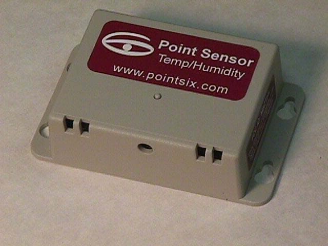
M5ZTHL
Mar 10, 2003Wireless Temperature/Humidity Sensor
Equipment Class
DSC - Part 15 Security/Remote Control Transmitter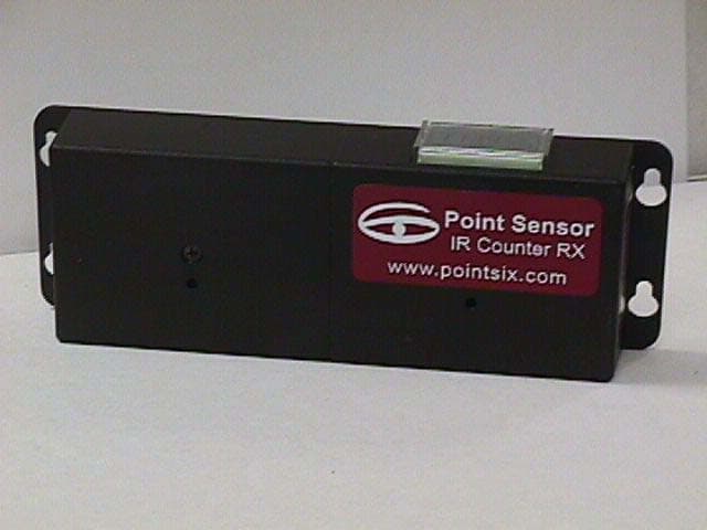
M5ZIRPC2
Mar 09, 2003IR Counter Transmitter
Equipment Class
DSC - Part 15 Security/Remote Control Transmitter