M6JN9702COLOR MONITOR
NPG Display Ltd Taiwan Branch
Click to zoom
Application Details
- Equipment Class
- JBP - Part 15 Class B Computing Device Peripheral
- Date of Grant
- Mar 26, 2000
- Application Purpose
- Original Equipment
- Date of Application
- Feb 18, 2000
- Equipment Note
- COLOR MONITOR
- Country
- Taiwan
Documents & Files
Document Text
Text extracted from the exhibit documents filed with the FCC. Open a document above to read the original.
Users Manual
1 SPECIFICATIONS Monitor Specifications MultiSync N9702 Monitor Notes Picture Tube Diagonal: Viewable: Image Size: Radius: 17 inch 16 inch 1210 mm 90° deflection, 0.26 mm dot pitch CRT, medium –short persistence phosphor, multi-layered anti static screen coating, semi-tint screen, Invar Shadow Mask and Opticlear screen surface. Input Signal Video: Sync: ANALOG 0.7Vp-p/75 Ohms Separate sync. Positive/Negative Display Color Analog input: Unlimited number of Colors Depends on display card used. Synchronization Horizontal: Range Vertical: 31 kHz to 86 kHz 55 Hz to 160 Hz Automatically Automatically Resolutions Supported Resolution based on horizontal and vertical frequencies only 640 × 480 @ 60 to 160 Hz 800 × 600 @ 55 to 137 Hz 832 × 624 @ 55 to 128 Hz 1024 × 768 @ 55 to 105 Hz 1152 × 870 @ 55 to 95 Hz 1280 × 1024 @ 55 to 80 Hz ......... 1600 × 1280 @ 55 to 68 Hz Some systems may not support all modes listed. NEC cites recommended resolution at 85 Hz for optimal display performance. Active Display Area (Factory Setting) Horizontal: Vertical: 310 mm 232 mm Dependent upon signal timing used, And does not include border area. Active Display Area (Full Scan) 325 mm 244 mm Dependent upon signal timing used, And does not include border area. Power Supply AC 100 - 240V, 50/60Hz Current Rating 2.2A @ 100 - 240V Dimensions 403 mm (W) × 420 mm (H) × 418 mm (D) Weight 16.0 kg Environmental Considerations Operating Temperature: Humidity: Feet: Storage Temperature: Humidity: Feet: 0° C to + 35° C 30% to 80% 0 to 10,000 Feet -20° C to + 60° C 10% to 90% 0 to 45,000 Feet NOTE: Technical specifications are subject to change without notice. 2 CONTROLS On-screen display control buttons on the front of the monitor function as follows: SELECT Enters and exits the OSM menu and decides the icon. CONTROL − / + Selects one of the controls and increases or decreases the adjustment. RESET Resets the highlighted control to the factory Setting. Adjusts the overall image and background screen brightness. Adjusts the image brightness in relation to the background. Red Color Control: Adjust the red contrast of the display. Green Color Control: Adjust the green contrast of the display. Blue Color Control: Adjust the blue contrast of the display. Moves the image horizontally (left or right). Moves the image vertically (up or down). Increases or decreases the horizontal size of the image. Increases or decreases the vertical size of the image. Increases or decreases the curvature of the sides either inward or outward. Increases or decreases the top of the screen to be the same as the bottom. Increases or decreases the tilt of the sides either to the left or right. Increases or decreases the curvature of the sides either to the left or right. Rotates the entire display clockwise or counterclockwise. Degauss Control: Eliminates the buildup of stray magnetic fields that alter the correct scan of the electron beams and affect the purity of the screen colors, focus and convergence. When activated, your screen image will jump and waver a bit as the screen is +– SELECTRESET 3 demagnetized. Caution: Please allows a minimum of 20 minutes to elapse between uses of the Degauss Control. 9300K This color setting is adjusted at the factory to the stated Kelvin Moves the OSM menu vertically (up or down). Moves the OSM menu horizontally (left or right). EXIT: To exit the OSM window. Select EXIT in “Icon select window”, then push SELECT button to exit OSM window. Note: If no buttons are pushed after 10 seconds while in OSM, the window will automactically disappear. 4 SERIAL NUMBER INFORMATION Refer to the serial number information shown below. SERIAL NUMBER LABEL Manufactured Year : ( Last digit ) Manufactured Month : January to September 1 to 9 October X NovemberY DecemberZ Factory mark : NPG CHINA ...............................Y It doesn’t have meaning specially MODEL SERIAL No. 00001 ~ on ward (Start from 00001 ~ when month is changed.) 5 DISASSEMBLY ü Before you disassemble the set, turn off power and pull out the power plug. ü Use a proper screwdriver. If you user screwdriver that does not fit, you may damage the screws. ü Disassembly is the opposite process of assembly. ü Carefully discharge the CRT anode potential by grounding to CRT dag ground harness before removing Anode Cap. MAIN BOARD and CRT BOARD EXPLANATION 1. Disassemble a screw like a picture. 2. Unsolder the GND wire (CRT coating earth wire) from MAIN BOARD ASSY and CRT BOARD ASSY. This model has two kinds of CRT. Depend on CRT, the GND wire assembly is some different. Be careful. 3. Disconnect the connector “S201”, “S202”, “S203”, Coating earth connector, and screen lead from the CRT BOARD ASSY. 4. Disconnect the CRT BOARD ASSY from the CRT. 5. Disconnect the connector “S301”, “S601”, “S703”, “S701”, “S104” and “P102” from the MAIN BOARD ASSY. 6. Remove the Anode Cap from the CRT. NOTE: Carefully discharge the CRT anode by shorting it to ground before removing Anode Cap. 6 ADJUSTMENT SPECIFICATIONS TABLE OF CONTENTS Page (1) Adjustment Tools ..................................................................................................................... 7 (2) Timing Table ........................................................................................................................... 7 (3) Definition for Normal Condition ................................................................................................. 7 (4) B+ Adjustment ........................................................................................................................ 7 (5) H. V. Adjustment ..................................................................................................................... 8 (6) X-ray Test ............................................................................................................................... 8 (7) H-Center Adjustment ..................................................................................................…
Text truncated - open the document above for the full version.
Cover Letter(s)
Federal Communications CommissionDate: Feb. 19, 2000 Authorization and Evaluation Division 7435 Oakland Mills Rd. Columbia, MD. 21046 Attention: Authorization and Evaluation Division Subject: Application for Certification on COLOR MONITOR (EUT) with FCC ID: M6JN9702 Dear Sir: We would like to apply for FCC certification of the EUT. Enclosed please find all required documents of the EUT listed below: 1. Exhibit 1 : The Authorization Letter signed by the applicant 2. Exhibit 2 : The FCC Label of EUT 3. Exhibit 3 : The modification List Letter signed by the applicant 4. Exhibit 4 : The RFI/EMI Test Report issued by ADT Corp. 5. Exhibit 5 : The photographs of EUT 6. Exhibit 6 : The Block Diagram & Schematic Diagram of EUT 7. Exhibit 7 : The User’s Manual of EUT Please review the information we submitted and issue us a grant for the EUT. If you have any questions or comments, please do not hesitate to contact Mr. Mike Su of ADT Lab. at fax no.: 886-2-2602-2943 or e-mail: [email protected] Sincerely yours, Cc. Mr. Mike Su / Advance Data Technology Corporation
External Photos
(Photo 1) FCC ID: M6JN9702 (Photo 2) FCC ID: M6JN9702 1 (Photo 3) FCC ID: M6JN9702 (Photo 4) FCC ID: M6JN9702 (Photo 5) FCC ID: M6JN9702 2 2 (Photo 6) FCC ID: M6JN9702 3 (Photo 7) FCC ID: M6JN9702 (Photo 8) FCC ID: M6JN9702 (Photo 9) FCC ID: M6JN9702 4 5 1 6 (Photo 10) FCC ID: M6JN9702 7 7 (Photo 11) FCC ID: M6JN9702 (Photo 12) FCC ID: M6JN9702 8 8 (Photo 13) FCC ID: M6JN9702
Test Report
ADVANCE DATA TECHNOLOGY CORPORATION REPORT NO.: F88110902 Page 1 FCC ID: M6JN9702 EMC TEST REPORT REPORT NO.: F88110902 MODEL NO.: N9702 DATE OF TEST: Nov. 16, 1999 PREPARED FOR : NPG DISPLAY LTD., TAIWAN BRANCH ADDRESS : 2FL-1, NO. 70, SEC. 2, TUN HWA S. RD., TAIPEI, TAIWAN, R.O.C. PREPARED BY:ADVANCE DATA TECHNOLOGY CORPORATION 11F, NO.1, SEC.4, NAN-KING EAST RD., TAIPEI, TAIWAN, R.O.C. This test report consists of 15 pages in total. It may be duplicated completely for legal use with the allowance of the applicant. It shall not be reproduced except in full, without the written approval of our laboratory. It should not be used by the client to claim product endorsement by NVLAP or any agency of the U.S. government. The test result in the report only applies to the tested sample. Accredited Laboratory ADVANCE DATA TECHNOLOGY CORPORATION REPORT NO.: F88110902 Page 2 FCC ID: M6JN9702 TABLE OF CONTENTS 1.CERTIFICATION..................................................................................................................3 2.GENERAL INFORMATION.................................................................................................4 2.1GENERAL DESCRIPTION OF EUT.........................................................................4 2.2DESCRIPTION OF SUPPORT UNITS.....................................................................5 2.3TEST METHODOLOGY AND CONFIGURATION................................................5 3.TEST INSTRUMENTS..........................................................................................................6 3.1TEST INSTRUMENTS (EMISSION)........................................................................6 3.2LIMITS OF CONDUCTED AND RADIATED EMISSION......................................7 4.TEST RESULTS (EMISSION)............................................................................................8 4.1RADIO DISTURBANCE...........................................................................................8 4.2EUT OPERATION CONDITION..............................................................................8 4.3TEST DATA OF CONDUCTED EMISSION............................................................9 4.4TEST DATA OF RADIATED EMISSION...............................................................11 5.PHOTOGRAPHS OF THE TEST CONFIGURATION WITH MINIMUM MARGIN........13 6.APPENDIX - INFORMATION OF THE TESTING LABORATORY................................15 ADVANCE DATA TECHNOLOGY CORPORATION REPORT NO.: F88110902 Page 3 FCC ID: M6JN9702 1. CERTIFICATION Issue Date: Jan. 25, 2000 Product:COLOR MONITOR Trade Name:NEC Model No.:N9702 Applicant:NPG DISPLAY LTD. TAIWAN BRANCH Standard:FCC Part 15, Subpart B, Class B CISPR 22: 1993+A1: 1995+A2: 1996, Class B ANSI C63.4-1992 We hereby certify that one sample of the designation has been tested in our facility on Nov. 16, 1999. The test record, data evaluation and Equipment Under Test (EUT) configurations represent herein are true and accurate representation of the measurements of the sample's EMC characteristics under the conditions herein specified. The test results show that the EUT as described in this report is in compliance with the Class B limits of conducted and radiated emission of applicable standards. ADVANCE DATA TECHNOLOGY CORPORATION Accredited Laboratory ADVANCE DATA TECHNOLOGY CORPORATION REPORT NO.: F88110902 Page 4 FCC ID: M6JN9702 2. GENERAL INFORMATION 2.1 GENERAL DESCRIPTION OF EUT Product:COLOR MONITOR Model No.:N9702 Power Supply Type:Switching Power Cord:Nonshielded (1.5m, 3-pin) Data Cable:Shielded (1.5m) Note: The EUT is a 17” color monitor with resolution up to 1600x1200. There is a ferrite core on the video cable outside the monitor. For more detailed features description, please refer to manufacturer's specification or User's Manual. ADVANCE DATA TECHNOLOGY CORPORATION REPORT NO.: F88110902 Page 5 FCC ID: M6JN9702 2.2 DESCRIPTION OF SUPPORT UNITS The EUT has been tested as an independent unit together with other necessary accessories or support units. The following support units or accessories are used to form representative test configuration during the tests. No.ProductBrandModel No.FCC IDI/O Cable 1. PERSONAL COMPUTER NTIPII-333T FCC DoC Approved Nonshielded Power (1.8m) 2. KEYBOARDFORWARDFDA-104GAF4ZDA-104GShielded Signal (1.4m) 3. MOUSEDEXINA2P800ANIYA2P800AShielded Signal (1.5m) 4. PRINTERHP2225C+DSI6XU2225 Shielded Signal (1.2m) Nonshielded Power (1.2m) 5. MODEMACEEX1414IFAXDM1414 Shielded Signal (1.2m) Nonshielded Power (1.2m) 6. VGA CARDCARDEXCD-GX2A44TICUVGA-GW710NA 2.3 TEST METHODOLOGY AND CONFIGURATION Both conducted and radiated testing were performed according to the procedures in ANSI C63.4: 1992. Radiated testing was performed at an antenna to EUT distance of 3/ 10 m on an open area test site. Please refer to the photos of test configuration in Item 5. ADVANCE DATA TECHNOLOGY CORPORATION REPORT NO.: F88110902 Page 6 FCC ID: M6JN9702 3. TEST INSTRUMENTS 3.1 TEST INSTRUMENTS (EMISSION) CONDUCTED EMISSION MEASUREMENT Description & ManufacturerModel No.Serial No.Calibrated Until ROHDE & SCHWARZ Test Receiver ESHS30828765/002Aug. 2, 2000 ROHDE & SCHWARZ Artificial Mains Network ESH2-Z5828075/003July 21, 2000 EMCO-L.I.S.N.3825/290031627July 21, 2000 Shielded RoomSite 5ADT-C05NA Note: 1. The measurement uncertainty is less than +/- 2.6dB, which is calculated as per NAMAS document NIS81. 2. The calibration interval of the above test instruments is 12 months. And the calibrations are traceable to NML/ROC and NIST/USA. RADIATED EMISSION MEASUREMENT Description & ManufacturerModel No.Serial No.Calibrated Until HP Spectrum Analyzer8590L3544A01176April 22, 2000 HP Preamplifier8447D2944A08485May 1, 2000 HP Preamplifier8347A3307A01088Aug. 30, 2000 ROHDE & SCHWARZ TEST RECEIVER ESMI 839013/007 839379/002 Aug. 30, 2000 SCHWARZBECK Tunable Dipole Antenna VHA 9103 UHA 9105 E101051 E101055 Nov. 25, 1999 CHASE BILOG AntennaCBL6112A2221Aug. 4, 2000 EMCO Turn Table1…
Text truncated - open the document above for the full version.
Contact Information
Applicant
Yasuhisa Okano(General Manager)
886 2 703-8262Fax: 886 2 702-9472
Technical Contact
ADVANCE DATA TECHNOLOGY CORPORATIONMIKE SU
[email protected]886-2-26032180
NO. 47, 14 LING, CHIA PAU TSUEN, LIN KOU HSIANG · TAIPEI HSIEN · Taiwan
Non-Technical Contact
ADVANCE DATA TECHNOLOGY CORPORATIONMIKE SU
[email protected]886-2-26032180
Test Firm
Bureau Veritas CPS (H.K.) Ltd. Taoyuan BranchRichard Chen
Technical Specifications
| # | Rule Parts | Frequency Range | Power Output |
|---|---|---|---|
| 1 | 15B | - | - |
Other Applications from NPG Display Ltd Taiwan Branch
M6JNL2501
Sep 05, 2002LCD Monitor
Equipment Class
JBP - Part 15 Class B Computing Device Peripheral
M6JNL1503
May 16, 2002LCD Monitor
Equipment Class
JBP - Part 15 Class B Computing Device Peripheral
M6JNL1501
Feb 06, 2002LCD Monitor
Equipment Class
JBP - Part 15 Class B Computing Device Peripheral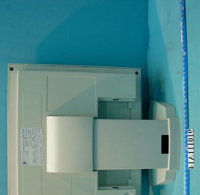
M6JNL1502
Jan 29, 2002LCD Monitor
Equipment Class
JBP - Part 15 Class B Computing Device Peripheral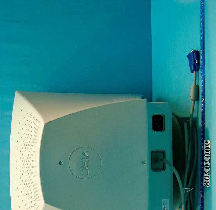
M6JN0706
Jun 18, 2001Color Monitor
Equipment Class
JBP - Part 15 Class B Computing Device Peripheral