M8YIDTElectronic Dog Trainer
DT Systems Inc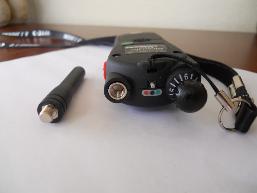
Click to zoom
Application Details
- Equipment Class
- DXX - Part 15 Low Power Communication Device Transmitter
- Date of Grant
- Jun 09, 2010
- Application Purpose
- Original Equipment
- Date of Application
- Jun 09, 2010
- Equipment Note
- Electronic Dog Trainer
- Frequency Range
- 27.09500000 - 27.09500000
- Company
- DT Systems Inc
- Country
- United States
Documents & Files
Document Text
Text extracted from the exhibit documents filed with the FCC. Open a document above to read the original.
Users Manual
SUPER TRAINER SUPER TRAINER TM TM Micro-iDT™ PLUS SERIES Electronic Dog Trainer Owner’s Manual • Micro-iDT™ PLUS (One Dog Trainer with Add-On Capability) 2 TABLE OF CONTENTS • Table of Contents .................................. 3 • Introduction............................................ 4 • Package Contents ................................. 5 • Model Features...................................... 5 • Parts & Functions .................................. 6 • Charging the Batteries........................... 11 • Turning ON and OFF............................. 12 • Testing................................................... 13 • Programming ......................................... 14 • Properly Fitting the Collar ...................... 15 • Setting the Intensity Level..................... 16 • Maintenance .......................................... 17 • Important Safety Notes.......................... 18 • Warranty ................................................ 19 • FCC & IC Compliance ........................... 19 • Contact Information ............................... 20 4 Congratulations and thank you for purchasing our Micro-iDT™ PLUS Training Collar with Add-On capability. It offers the Maxx-Range™ Internal Antenna System, the industry’s only internally woven antenna in the collar. With up to a 900 yard range, they are perfect for use around the house and versatile enough to use out in the field. Micro-iDT™ PLUS series collars feature sixteen levels of intensity with an easy ‘no-look’ clicking intensity selection dial. This model includes both Momentary ‘Nick’ and Continuous stimulations, and Positive Vibration. The collars are 100% waterproof and can be worn even when the dog is submerged. The Micro-iDT™ PLUS Series Dog Training Collar is durable, safe, and very humane when used correctly. The automatic safety shut-off feature stops the stimulation after 8 seconds to prevent accidental or prolonged stimulation. Thanks again for choosing D.T. Systems to help bring out the best in your best friend! INTRODUCTION IMPORTANT NOTE : Please read this owner’s manual in its entirety before operating this unit. Should you have any questions about our collars or their operation please contact our Customer Service department (see back page for contact information). PACKAGE CONTENTS • Transmitter* • Collar Receiver • Rechargeable Batteries for the Collar (already in- stalled in collar unit) • Battery Charger • Splitter/Adaptor Charging Cable • Test Light • Owner’s Manual *9-volt transmitter battery not included MODEL FEATURES • Digital Technology • Up to 900 yard range • Expandable to 2- or 3-dog system with Micro-iDT Add-On collar units (sold separately) • Lightweight, compact collar and transmitter • 16 adjustable intensity levels of Momentary (‘Nick’) Stimulation and Continuous Stimulation • Positive Vibration • Rechargeable Ni-MH battery system in collar • Completely waterproof collars • Weather resistant transmitter • Gentle Touch System™ Extra Mild Stimulation • MAXX-Range™ Internal Antenna System in collar belt • Built in safety shut-off system 6 Transmitter PARTS & FUNCTIONS Intensity Selection Dial Collar Selecting Switch Antenna LED Indicator Light Vibration Button Magnet Indicator (Red Mark) Model Number Momentary “Nick” Stimulation Button Continuous Stimulation Button Battery Cover (back side) PARTS & FUNCTIONS Intensity Selection Dial The intensity selection dial can be set from level 1 to level 16 to find the exact stimulation level for your dog (see page 16). Transmitter Antenna Be sure to check that the antenna is securely fas- tened to the transmitter before each use. Hand- tightened only. Be careful when screwing the an- tenna into the transmitter. Over-tightening the an- tenna can cause damage to the antenna or the antenna mount. Magnet Indicator (Red Mark) The RED mark indicates the location of the magnet in the transmitter. The indi- cator is used to turn the receiver ON/ OFF and for ID programming. Transmitter Indicator Light When one of the buttons on the transmitter is pushed, the Red LED light will turn on to indicate that the transmitter is being operated. If the Red LED light blinks rapidly after pressing any of the transmitter buttons, the 9-volt battery will need to be replaced soon. 8 PARTS & FUNCTIONS Collar Selecting Switch Switching between collar units can be controlled by moving the toggle selection switch to the desired unit. Remote Training Buttons Pressing the “NICK” button will make the collar give a Momentary, or ‘Nick’ Stimulation. Pressing the “CONT” button gives a Continuous Stimula- tion. Pressing the red button on the left side will make the collar Vibrate only. Collar Receiver Battery Charging Receptacle LED Indicator Light Red Mark (Magnetic Switch Indicator) Contacts Collar Belt with Embedded Re- ceiver Antenna Red Mark on the Collar Unit The Red Mark indicates the location of the Magnet Switch in the receiver. To turn the receiver ON/OFF, touch and hold the Red Mark with the Magnet Indicator (Red Mark) on the side of the transmitter until the LED light on the Collar unit starts to flash. PARTS & FUNCTIONS Collar Indicator Light When the Collar Receiver is turned on, the Red LED light will flash steadily once every two seconds to indicate that the unit is active. The Red LED light changes to a rapid flash when the battery is in need of charging. The Red LED light stays lit while plugged into the charger. CAUTION If your collar belt is too long , we recommend looping the excess collar belt back around through the buckle. We DO NOT recommend cutting the collar belt. Cutting the collar belt too much will drastically reduce the range of your collar unit. However, the collar belt can be cut up to about 3 inches without affecting the range too much. Collar Belt with MAXX-Range™ Antenna The embedded collar antenna is woven into the collar belt, and runs along the entire length of the belt. 10 Contacts Contacts should fit snugly against the dog’s neck to en…
Text truncated - open the document above for the full version.
Cover Letter(s)
On Your Company Letterhead May 5, 2010 Equipment Authorization Division Federal Communications Commission 7435 Oakland Mills Road Columbia, MD 21046 FCC ID: M8YIDT Product Name: Micro iDT Plus Request for Confidentiality Pursuant to Sections 0.457 and 0.459 of the Commission’s rules, we hereby request that the following documents be held confidential: • Schematics • Block diagram • Operational Description These materials contain trade secrets and proprietary information and are not customarily released to the public. The public disclosure of this information might be harmful to the company and provide unjustified benefits to our competitors. Dated this 5 Day of May 20 10 By: J. S. Kim Signature Printed Title: President On behalf of : D. T. Systems, Inc. Telephone: 214‐350‐9446 D.T. SYSTEMS, INC. 2872 Walnut Hill Lane Dallas, Texas 75229 214-350-9446
Cover Letter(s)
On Your Company Letterhead May 5, 2010 Nemko Canada Inc 303 River Road Ottawa, Ontario, Canada K1V 1H2 Attn: Director of Certification Authority to Act as Agent FCC On our behalf, I appoint Nemko USA, Inc. at 802 N Kealy Avenue, Lewisville TX 75057 to act as our agent in the preparation of this application for equipment certification. I certify that submitted documents properly describe the device or system for which equipment certification is sought. I also certify that each unit manufactured, imported or marketed, as defined in FCC regulations will have affixed to it a label identical to that submitted for approval with this application. We also authorize Nemko USA, Inc. to certify that neither the applicant nor any party to the application is subject to a denial of Federal benefits, that include FCC benefits, pursuant to Section 5301 of the Anti‐Drug Abuse Act of 1988, 21 U.S.C. § 862 because of a conviction for possession or distribution of a controlled substance. For instances where our authorized agent signs the application for certification on our behalf, I acknowledge that all responsibility for complying with the terms and conditions for certification, as specified by Nemko Canada Inc, still resides with D. T. Systems, Inc., 2872 Walnut Hill Lane, Dallas, TX 75229. Dated this 5 Day of May 20 10 Agency agreement expiration date: May 5, 2011 By: J. S. Kim Signature Printed Title: President On behalf of : D. T. Systems, Inc. Telephone: 214‐350‐9446 D.T. SYSTEMS, INC. 2872 Walnut Hill Lane Dallas, Texas 75229 214-350-9446
Test Report
Nemko Test Report: 43653RUS1Rev2 Applicant: D.T. Systems 2872 Walnut Hill Lane Dallas, TX 75229 USA Equipment Under Test: Micro iDT Plus (E.U.T.) In Accordance With: CFR 47, Paragraph 15.227 Operation in the Band 26.96 to 27.28 MHz TESTED BY: DATE: 31 March 2010 David Light, Senior Wireless Engineer APPROVED BY: DATE: 09 June 2010 Tom Tidwell, Telecom Direct Total Number of Pages: 14 Nemko USA, Inc. CFR 47, Paragraph 15.227 Operation in the Band 26.96 to 27.28 MHz EQUIPMENT: Micro iDT Plus Test Report No.: 43653RUS1Rev2 Page of 14 2 Table of Contents SECTION 1. SUMMARY OF TEST RESULTS 3 SECTION 2. EQUIPMENT UNDER TEST (E.U.T.) 5 SECTION 3. RADIATED EMISSIONS 7 SECTION 4. BLOCK DIAGRAMS 11 SECTION 5. TEST EQUIPMENT LIST 12 ANNEX A 13 Nemko USA, Inc. CFR 47, Paragraph 15.227 Operation in the Band 26.96 to 27.28 MHz EQUIPMENT: Micro iDT Plus Test Report No.: 43653RUS1Rev2 Page of 14 3 Section 1. Summary of Test Results Manufacturer: D.T. Systems Model No.: Micro iDT Plus Serial No.: 801286 General: All measurements are traceable to national standards. These tests were conducted on a sample of the equipment for the purpose of demonstrating compliance with FCC CFR 47, Paragraph 15.227. All tests were conducted using measurement procedure ANSI C63.4-2003. Radiated emissions are made on an open area test site. A description of the test facility is on file with the FCC. New Submission Production Unit Modification Filing Pre-Production Unit THIS TEST REPORT RELATES ONLY TO THE ITEM(S) TESTED. THE FOLLOWING DEVIATIONS FROM, ADDITIONS TO, OR EXCLUSIONS FROM THE TEST SPECIFICATIONS HAVE BEEN MADE. See “ Summary of Test Data”. Nemko USA, Inc. authorizes the above named company to reproduce this report provided it is reproduced in its entirety and for use by the company’s employees only. Any use which a third party makes of this report, or any reliance on or decisions to be made based on it, are the responsibility of such third parties. Nemko USA, Inc. accepts no responsibility for damages, if any, suffered by any third party as a result of decisions made or actions based on this report. This report applies only to the items tested. Nemko USA, Inc. CFR 47, Paragraph 15.227 Operation in the Band 26.96 to 27.28 MHz EQUIPMENT: Micro iDT Plus Test Report No.: 43653RUS1Rev2 Page of 14 4 Summary Of Test Data Name of Test Paragraph Number Results Radiated Emissions 15.209 / 15.227 Complies Powerline Conducted Emissions RSS-General, 7.2.2 N/A Notes: 1) The EUT is battery powered Nemko USA, Inc. CFR 47, Paragraph 15.227 Operation in the Band 26.96 to 27.28 MHz EQUIPMENT: Micro iDT Plus Test Report No.: 43653RUS1Rev2 Page of 14 5 Section 2. Equipment Under Test (E.U.T.) General Equipment Information Frequency Range: 26.96 to 27.28 MHz Operating Frequency(ies) of Sample: 27.095 MHz (fixed) Type of Emission: F1D Emission Designator: 9K50F1D Input Power: 9 Vdc (battery) Antenna: Integral Nemko USA, Inc. CFR 47, Paragraph 15.227 Operation in the Band 26.96 to 27.28 MHz EQUIPMENT: Micro iDT Plus Test Report No.: 43653RUS1Rev2 Page of 14 6 Description of E.U.T. The Micro iDT Plus is a handheld wireless transmitter for training dogs. System Diagram Nemko USA, Inc. CFR 47, Paragraph 15.227 Operation in the Band 26.96 to 27.28 MHz EQUIPMENT: Micro iDT Plus Test Report No.: 43653RUS1Rev2 Page of 14 7 Section 3. Radiated Emissions NAME OF TEST: Radiated Emissions PARA. NO.: 15.209 / 15.227 TESTED BY: David Light DATE: 19 March 2010 Test Results: Complies. The maximum field strength of the fundamental emission is 72.2 dBμV/m @ 3 meters. This is 7.8 dB below the specification limit of 80 dBμV/m @ 3m. Test Data: See next page. Test Equipment Used: 1554-1733-1763-1767-1783 Measurements 9 kHz to 30 MHz RBW=VBW=10 kHz Measurements 30 to 1000 MHz: RBW=VBW=100 kHz Detector: Peak The spectrum was searched from 9 kHz to 1000 MHz. All emissions within 20 dB of the specification limit are reported. The device was tested on three orthogonal axes. Fresh batteries were used in testing this device. Nemko USA, Inc. CFR 47, Paragraph 15.227 Operation in the Band 26.96 to 27.28 MHz EQUIPMENT: Micro iDT Plus Test Report No.: 43653RUS1Rev2 Page of 14 8 Band edge Nemko USA, Inc. CFR 47, Paragraph 15.227 Operation in the Band 26.96 to 27.28 MHz EQUIPMENT: Micro iDT Plus Test Report No.: 43653RUS1Rev2 Page of 14 9 Test Data – Radiated Emissions Meas.Ant.Atten.MeterAntennaPathRFCorrectedSpec.CR/SLPass Freq.Pol.Reading FactorLossGainReadinglimitDif f .Fail (MHz)(H/V )(dB)(dBuV )(dB)(dB)(dB)(dBuV /m) (dBuV /m)(dB)Unc.Comment 27Loop05615.21.00.072.280.0-7.8PassCarrier Op erator: D. Ligh t Mode l: M icro iDT Plu s Freque ncyField Strength Field St re ngthMargin (MHz)B LimitsdB(uV/m@3m)(dB) 3 0.040.019.3-20.7 1 12.243.522.3-21.2 7 58.346.041.9-4.1 8 94.046.043.8-2.2 9 21.346.044.6-1.4 9 48.646.043.4-2.6 9 75.854.049.1-4.9 Nemko Radia ted Emissions 30 M Hz - 1 GHz Nemko FCC Class B 30MHz -1GHz Horizontal Scan 30.0M230.0M430.0M630.0M830.0M Frequency (H z ) 0 10.0 20.0 30.0 40.0 50.0 60.0 70.0 80.0 Limit Level (dBuV/m) Company: Model N umber: 08:29:10 AM, Friday, March 19, 2010 Operator: Scan FCC B Limit Scan Peaks Peaks Nemko USA, Inc. CFR 47, Paragraph 15.227 Operation in the Band 26.96 to 27.28 MHz EQUIPMENT: Micro iDT Plus Test Report No.: 43653RUS1Rev2 Page of 14 10 Nemko FCC Class B 30MHz -1GHz Vertical Scan 30.0M230.0M430.0M630.0M830.0M Frequency 0 10.0 20.0 30.0 40.0 50.0 60.0 70.0 80.0 A mplit ude ( dbuV/m) Company: Model N umber: 08:33:05 AM, Friday, March 19, 2010 Operator: Scan FCC B Limit Scan Peaks Peaks Nemko USA, Inc. CFR 47, Paragraph 15.227 Operation in the Band 26.96 to 27.28 MHz EQUIPMENT: Micro iDT Plus Test Report No.: 43653RUS1Rev2 Page of 14 11 Section 4. Block Diagrams Test Site For Radiated Emissions 3 METERS E.U.T. NON-CONDUCTING TURN-TABLE 0.8 METER VARIABLE SEARCH HEIGHT (1 TO 4 m) TO TEST RECEIVER/SPECTRUM ANALYZER SEARCH ANTENNA Nemko USA, Inc. CFR 47, Paragraph 15.227 Operation in the Band 26.96 to 27.28 MHz EQUIPMENT: Mic…
Text truncated - open the document above for the full version.
Contact Information
Applicant
Bryant Kim(VP)
Technical Contact
D.T. SystemsBryant Kim
[email protected]214-350-9446
2872 Walnut Hill Lane · Dallas, Texas · United States
Non-Technical Contact
D.T. SystemsBryant Kim
[email protected]214-350-9446
Test Firm
Nemko Dallas, Inc.Mike Cantwell
Technical Specifications
| # | Rule Parts | Frequency Range | Power Output |
|---|---|---|---|
| 1 | 15C | 27.095 MHz - 27.095 MHz | - |
Other Applications from DT Systems Inc
M8YRAPT
Jan 12, 2014remote control for a canine training collar
Equipment Class
DXX - Part 15 Low Power Communication Device Transmitter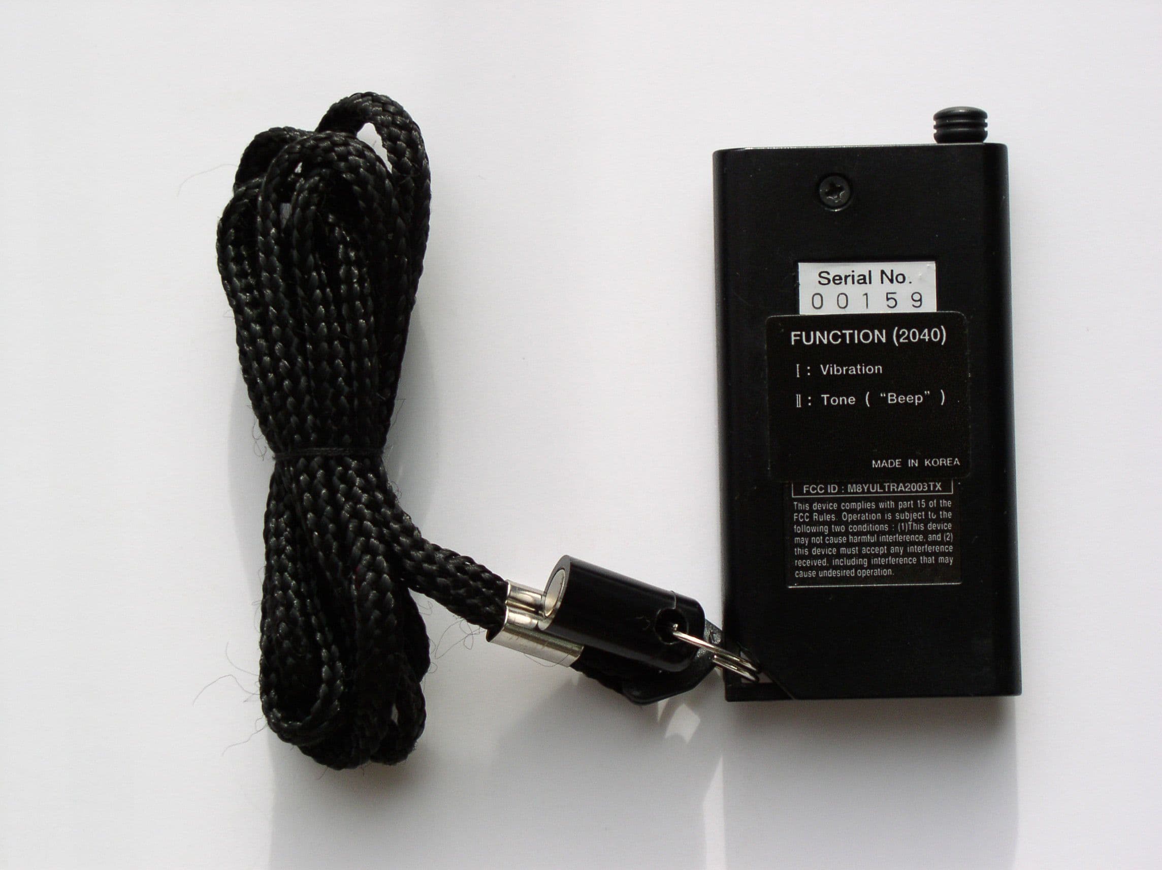
M8YULTRA2003TX
Feb 02, 2003Dog Collars
Equipment Class
DSC - Part 15 Security/Remote Control Transmitter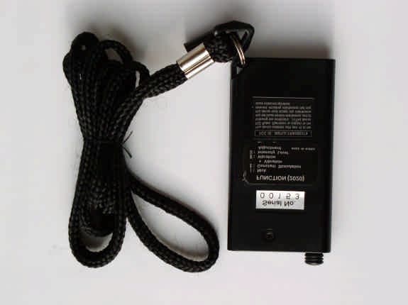
M8YULTRA2002TX
Feb 02, 2003Dog Collars
Equipment Class
DSC - Part 15 Security/Remote Control Transmitter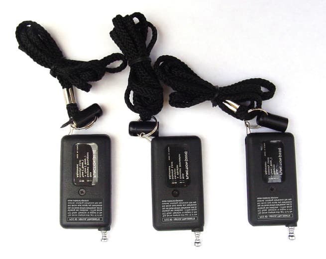
M8YULTRA2000TX
Aug 23, 2001Dog Collars
Equipment Class
DSC - Part 15 Security/Remote Control Transmitter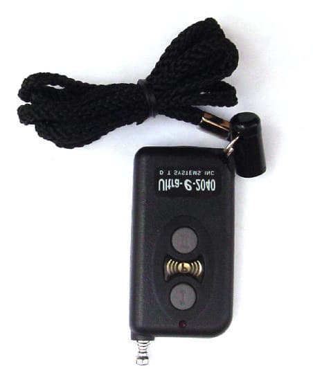
M8YULTRA2001TX
Aug 13, 2001Dog Collars
Equipment Class
DSC - Part 15 Security/Remote Control Transmitter