M8YRAPTremote control for a canine training collar
DT Systems Inc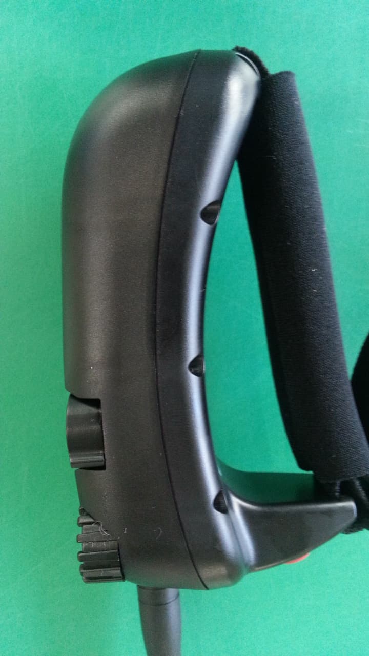
Click to zoom
Application Details
- Equipment Class
- DXX - Part 15 Low Power Communication Device Transmitter
- Date of Grant
- Jan 12, 2014
- Application Purpose
- Original Equipment
- Date of Application
- Jan 12, 2014
- Equipment Note
- remote control for a canine training collar
- Frequency Range
- 26.99500000 - 26.99500000
- Company
- DT Systems Inc
- Country
- United States
Documents & Files
Document Text
Text extracted from the exhibit documents filed with the FCC. Open a document above to read the original.
Users Manual
24 2872 Walnut Hill Lane Dallas, Texas 75229 Tel: (214) 350-9446, (888) 588-8364 Fax: (214) 350-7847 Website: www.dtsystems.com E-mail: [email protected] 1-RAPT 2013.03.20 Printed in Korea • R.A.P.T. 1400 • R.A.P.T. 1400 CoverUp • R.A.P.T. 1450 • R.A.P.T. 1400 Elite R.A.P.T. Series with SmartLED Owner’s Manual 2 NOTICE! According to how you use your transmitter, the transmitting range might be much different. You will have more range if you use your transmitter apart from your body as follows: Maximum Typical Range Minimum Range IMPORTANT NOTE : Please read this owner’s manual in its entirety bef ore operating this unit. Should you have any questions about our collars or their operation please contact our Customer Service department (see back page for address and phone number information). 23 FCC/IC/CE COMPLIANCE Your R.A.P.T. Series TM Trainer has been manufactured under complete compliance with Part 15 of the Federal Communication Commission (FCC) rules, Industry Canada (IC) Standard RSS-310, and A rticle 3 of the Directive 1999/5/EC. The complex internal structure of each product has been designed to operate within specific regulation s of FCC specifications. Any changes or modifications not expressly approved by the manufacturer is a violation of these specifications and could vo id the user's authority to operate the equipment. This device complies with Part 15 of the FCC rules su bject to the following two conditions: 1. This device may not cause harmful interference 2. This device must accept all interference received, i ncluding interference that may cause undesired operation. Note: This equipment has been tested and found to c omply with the limits for a Class B digital device, pursuant to part 15 of the FCC Ru les. These limits are designed to provide reasonable protection against harmful inter ference in a residential installation. This equipment generates, uses and can radiate radi o frequency energy and, if not installed and used in accordance with the instructi ons, may cause harmful interference to radio communications. However, ther e is no guarantee that interference will not occur in a particular install ation. If this equipment does cause harmful interference to radio or television recepti on, which can be determined by turning the equipment off and on, the user is encou raged to try to correct the interference by one or more of the following measur es: - Reorient or relocate the receiving antenna. - Increase the separation between the equipment and receiver. - Connect the equipment into an outlet on a circuit different from that to which the receiver is connected. - Consult the dealer or an experienced radio/TV tec hnician for help. This Category II radiocommunication device complies with Industry Canada Standard RSS-310. 26.96-27.28.10mv. Ce dispositif de radiocommunication de catégorie II respecte la norme CNR-310 d'Industrie Canada. Declaration of Conformity (Directive 1999/5/EC) D.T. Systems, Inc. declares that the R.A.P.T. Series TM products are in compliance with the essential requirements under Ar ticle 3 of the R&TTE Directive 1999/5/EC by application of the following standards: Article 3.1(a) - EN 60950-1 Article 3.1(b) - EN 301 489-1 V1.8.1, EN 301 489-3 V1.4.1 Article 3.2 - EN 300 220-1 V2.1.1, EN 300 220-2 V2. 1.2 22 WARRANTY • D.T. Systems Premium Lifetime Warranty is the best w arranty offered in the industry. This warranty is free to participa ting U.S. customers (a completed warranty registration card must be return ed within 30 days of original purchase). This changes our normal one year parts and labor warranty to a limited lifetime warranty again st manufacturing defects on parts and a one year warranty on labor. How the Limited Lifetime Warranty works: • To qualify for the Warranty you must fill out the wa rranty registration card which came with your system and mail it (with your original sales receipt) to D.T. Systems within 30 days of purchase. • Your unit must be sent to D.T. Systems for all warra nty issues. • There is no charge for parts or labor for the first year on any of our lifetime warranty products. • When the product’s labor warranty expires after the first year, there will be a normal labor charge for any repair under the l ifetime warranty program should your system be in need of service. Labor charges will vary depending on: 1) the system model and 2) the severity of the repair needed. • When your unit is sent in for repairs, any defectiv e part(s) that need replacement will be free during the lifetime warran ty period. What is covered: D.T. Systems Premium Lifetime Warranty covers all pa rts to be free from manufacturing defects for as long as the unit is he ld by the original owner. What is not covered: • Rechargeable batteries have a one year warranty fro m the original purchase date and are not part of our lifetime warr anty. • Lost parts or parts that malfunction due to abuse, misuse, improper maintenance, or incorrect handling are not covered. • Damage from dogs chewing or wear and tear from exce ssive field use is not covered. • Our warranty does not cover the cost of shipping th e unit to our repair center. Return ground shipping (inside the contine ntal United States) to the customer is covered. However, expedited or special shipping is not covered, but available by request for an extra shipping fee. International shipping charges are not covered. 3 TABLE OF CONTENTS • Table of Contents .................................. .....3 • Introduction....................................... ..........4 • Package Contents ................................... ...5 • Model Features..................................... ......5 • Parts & Functions .................................. .....6 • SmartLED........................................... ........11 • Charging the Batteries............................. ...12 • Turning ON and OFF................................. .13 • Testing ............................................ ....…
Text truncated - open the document above for the full version.
Operational Description
General Information and operation of TX & RX 1. General information A. TX Equipment under test R.A.P.T. 14xx Model name R.A.P.T. 1400 Variant model name R.A.P.T. 1400 CoverUP, R.A.P.T. 1400 Elite, R.A.P.T. 1450, R.A.P.T. 1450 CoverUP, R.A.P.T. 1450 Elite Serial number ***** Frequency range 26.995MHz Modulation technique ASK Number of channels 1 Antenna type Connector type(Coil antenna) Power source DC 9.0V(Alkaline Battery) B. RX Equipment under test R.A.P.T. 14xx Model name R.A.P.T. 1400 RX Variant model name R.A.P.T. 1400 CoverUP Rx, R.A.P.T. 1400 Elite Rx, R.A.P.T. 1450 Rx, R.A.P.T. 1450 CoverUP Rx Serial number ***** Frequency range 26.995MHz (Rx) Modulation technique ASK Number of channels 1 Antenna type Fixed type(Wire antenna) Power source DC 4.8V(Ni-MH Batteries) 2. Test frequency Low channel Middle channel High channel Frequency(MHz) 26.995 - - 3. Operations A. TX i. Electric Voltage Use 9V-DC Alkaline battery. ii. Operations(TX) 1. Digital Board Once the power switch is ON, 9VDC electric voltage which is provided from 9VDC battery will be 5VDC thorough regulator which is installed on the board. 5VDC electric voltage will provide the power to microprocessor of the PCB, RF oscillator of RF board and 1 st RF amplifier. LED will operate only when the switch is ON. When the unit is normal, it will always ON and when low battery, it will flash for 5 seconds after power OFF. 3 DOGS switch determines the ID of transmitter. In other words, the location of switch knob indicates their ID according to the location(left, center, right). The Intensity has 16 levels(from1 to 16) and has each different signal. The receiver which receives the signal from Transmitter generates the shock voltage. Once a switch is pushed, a regulator operates and makes 5VDC. The microprocessor provided 5VDC searches both dog switch and intensity level switch if Nick or Continuous switch is pushed. And if vibration switch is pushed, it searches dog switch only and send the optimal signal to RF modulation. 2. RF Board A square wave from microprocessor will be modulated at oscillator that consists of Crystals(26.995MHz) and TRs. The oscillator will oscillate when Power is provided, then the signal oscillated will be provided to the 1 st amplifier. The signal from 1 st amplifier will be amplified by the 1 st amplifier(2SC4226), and then the signal that amplified by the final amplifier(2SC4272) will be radiated through an antenna. A ground system has its own ground method. iii. Operations(RX) 1. Main Board Charging process i. It will be provide 12VDC from a charger. ii. It will charge the battery as the charging circuit changes. iii. When charging, it will not operate. Operation i. The electric power will be changed to 3.3VDC through a regulator and be provided to the microprocessor. The microprocessor will adjust the regulator so as to provide the voltage continuously. ii. The receive will get a signal from a Rx modulator. iii. When low battery, it will send the signal to the microprocessor. 2. RX module The signal(26.995MHz) from a transmitter goes to a low filter(28MHz) and will be amplified by an amplifier. A mixed circuit will change the 1 st 16.295MHz signal to 10.7MHz signal. Then the signal of 10.7MHz will be input to ‘IF IC(NJM2527V)’ through a 10.7MHz ceramic filter(NJM2537V). The ‘IF IC(NJM2537V’ will make 455KHz signal, and pass 455KHz filer, finally get audio signal. This audio signal passes RC filter and becomes pure signal, then make a squire wave using signal from transmitter. The squire wave will be input to the microprocessor on the main PCB.
Test Report
NVLAP Lab Code 100426-0 This report must not be used to claim product certification, approval, or endorsement by NVLAP, NIST, or any agency of the Federal Government. Nemko USA, Inc. is a NVLAP accredited laboratory . Test Report issued under the responsibility of: www.nemko.com TEST REPORT FCC Part 15 Radio Frequency Devices Subpart C – Intentional Radiators RSS 310 Low Power Licence-exempt Radio Apparatus: Category II Equipment FCC ID ......... : M8YRAPT Report Reference No. ...................... : 10247674_TRF_Part 15 Compiled by (+ signature) ................ : Arturo Ruvalcaba Approved by (+ signature) ................. : Tom Tidwell Date of issue .................................... : 10-Dec-13 Report Revision ................................ : 0 Total number of pages ..................... : 34 Testing Laboratory .......................... : Nemko USA, Inc. (Dallas) Address ............................................ : 802 N. Kealy Ave. Lewisville, TX 75057 USA Tel: +1 972 436 9600 Fax: +1 972 436 2667 Applicant’s name ............................. : DT Systems, Inc. Address .............................................. : 2872 Walnut Hill Lane, Dallas, Texas 75229 Model(s) .......................................... : RAPT 1400 Test specification: Standard ............................................ : 47 CFR Part 15 Subpart C & RSS 310 Issue 2 Test procedure ................................... : ANSI C63.4:2009 Non-standard test method ................. : N/A TRF Revision ..................................... : 26-Apr-13 Nemko USA, Inc. 802 N. Kealy Ave. Lewisville, TX USA Page 1 of 34 Tel: +1 972-436-9600 Fax: +1 972-436-9600 47 CFR Part 15 Subpart C & RSS 310 Issue 2 Report Number: 10247674_TRF_Part 15 Revision: 0 Issue Date: 10-Dec-13 Revision History # Description Date 0 Original Report Release 10-Dec-13 Notices: 1. This report shall not be reproduced, except in full, without the written approval of the Issuing testing laboratory. 2. The test results presented in this report relate only to the object tested. 3. The results contained in this report reflect the results for this particular model and serial number. It is the responsibility of the manufacturer to ensure that all production models meet the intent of the requirements detailed within this report. 4. "(see Enclosure #)" refers to additional information appended to the report. 5. Throughout this report a point is used as the decimal separator. 6. Dimensions in English units for convenience only, metric units prevail. Nemko USA, Inc. 802 N. Kealy Ave. Lewisville, TX USA Page 2 of 34 Tel: +1 972-436-9600 Fax: +1 972-436-9600 47 CFR Part 15 Subpart C & RSS 310 Issue 2 Report Number: 10247674_TRF_Part 15 Revision: 0 Issue Date: 10-Dec-13 Table of Contents Revision History .................................................................................................................................................................. 2 Normative References ........................................................................................................................................................ 4 Equipment Under Test (EUT) ............................................................................................................................................. 5 Details: ........................................................................................................................................................................... 5 EUT Configuration .......................................................................................................................................................... 6 EUT Photo(s).................................................................................................................................................................. 8 Summary of Testing .......................................................................................................................................................... 10 Testing Location ........................................................................................................................................................... 11 Procedural Requirements ............................................................................................................................................ 12 United States ............................................................................................................................................................ 12 Canada ..................................................................................................................................................................... 12 Information to the User and Labeling Requirements ........................................................................................................ 12 United States ................................................................................................................................................................ 12 Labeling .................................................................................................................................................................... 12 Information to User .................................................................................................................................................. 13 Canada ......................................................................................................................................................................... 13 Labeling .................................................................................................................................................................... 13 User Manual Statements ......................................................................................................................................... 13 Technical Requirements ...................................................................…
Text truncated - open the document above for the full version.
Test Setup Photos
47 CFR Part 15 Subpart C & RSS 310 Issue 2 Report Number: 10247674_TRF_Part 15 Revision: 0 Issue Date: 10-Dec-13 Nemko USA, Inc. 802 N. Kealy Ave. Lewisville, TX USA Page 32 of 34 Tel: +1 972-436-9600 Fax: +1 972-436-9600 Setup Photos 47 CFR Part 15 Subpart C & RSS 310 Issue 2 Report Number: 10247674_TRF_Part 15 Revision: 0 Issue Date: 10-Dec-13 Nemko USA, Inc. 802 N. Kealy Ave. Lewisville, TX USA Page 33 of 34 Tel: +1 972-436-9600 Fax: +1 972-436-9600 Photo 3 Test Setup – 9 kHz – 30 MHz Supplemental Information: Photo 4 Test Setup – 30 MHz – 1 GHz Supplemental Information: 47 CFR Part 15 Subpart C & RSS 310 Issue 2 Report Number: 10247674_TRF_Part 15 Revision: 0 Issue Date: 10-Dec-13 Nemko USA, Inc. 802 N. Kealy Ave. Lewisville, TX USA Page 34 of 34 Tel: +1 972-436-9600 Fax: +1 972-436-9600 Photo 5 Test Setup – EUT worst-case orientation Supplemental Information:
Contact Information
Applicant
Bryant Kim(VP)
Technical Contact
Non-Technical Contact
Nemko USAJenny Gibbs
[email protected]940-455-2246
Test Firm
Nemko Dallas, Inc.Jenny Gibbs
[email protected]9724369200
Technical Specifications
| # | Rule Parts | Frequency Range | Power Output |
|---|---|---|---|
| 1 | 15C | 26.995 MHz - 26.995 MHz | - |
Other Applications from DT Systems Inc
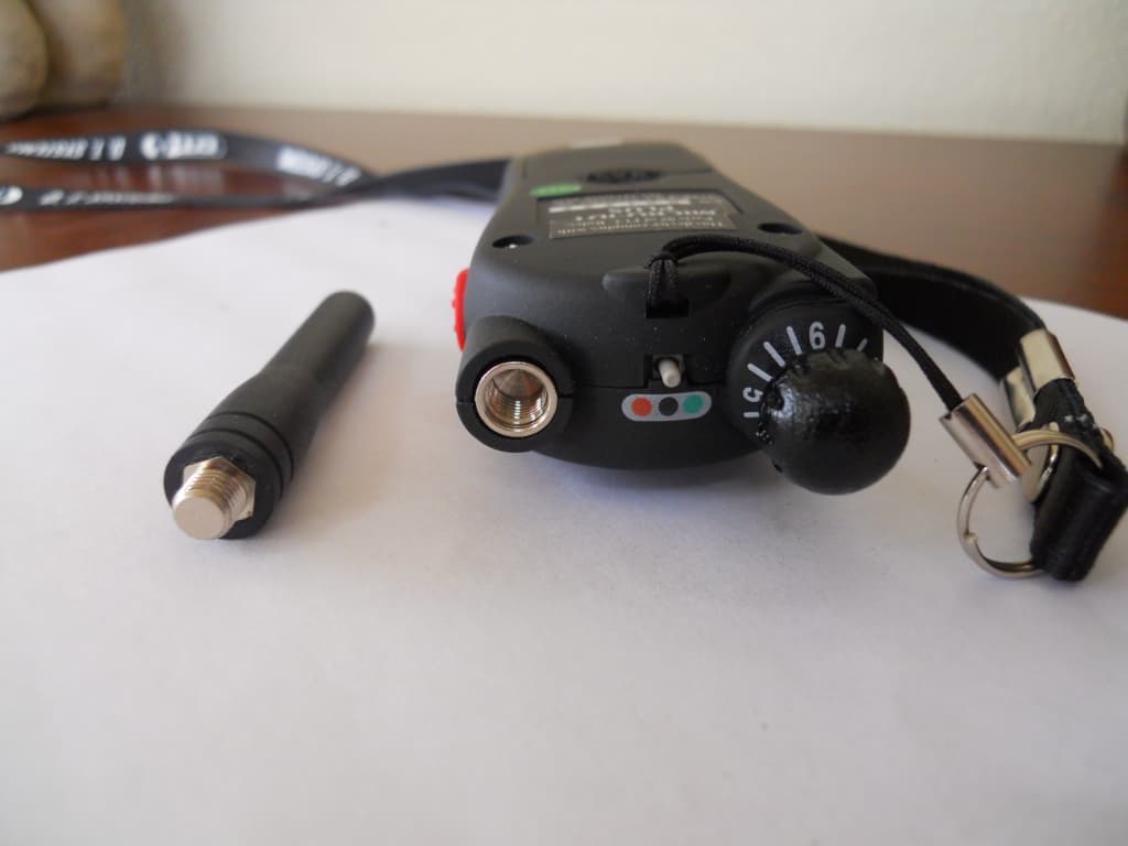
M8YIDT
Jun 09, 2010Electronic Dog Trainer
Equipment Class
DXX - Part 15 Low Power Communication Device Transmitter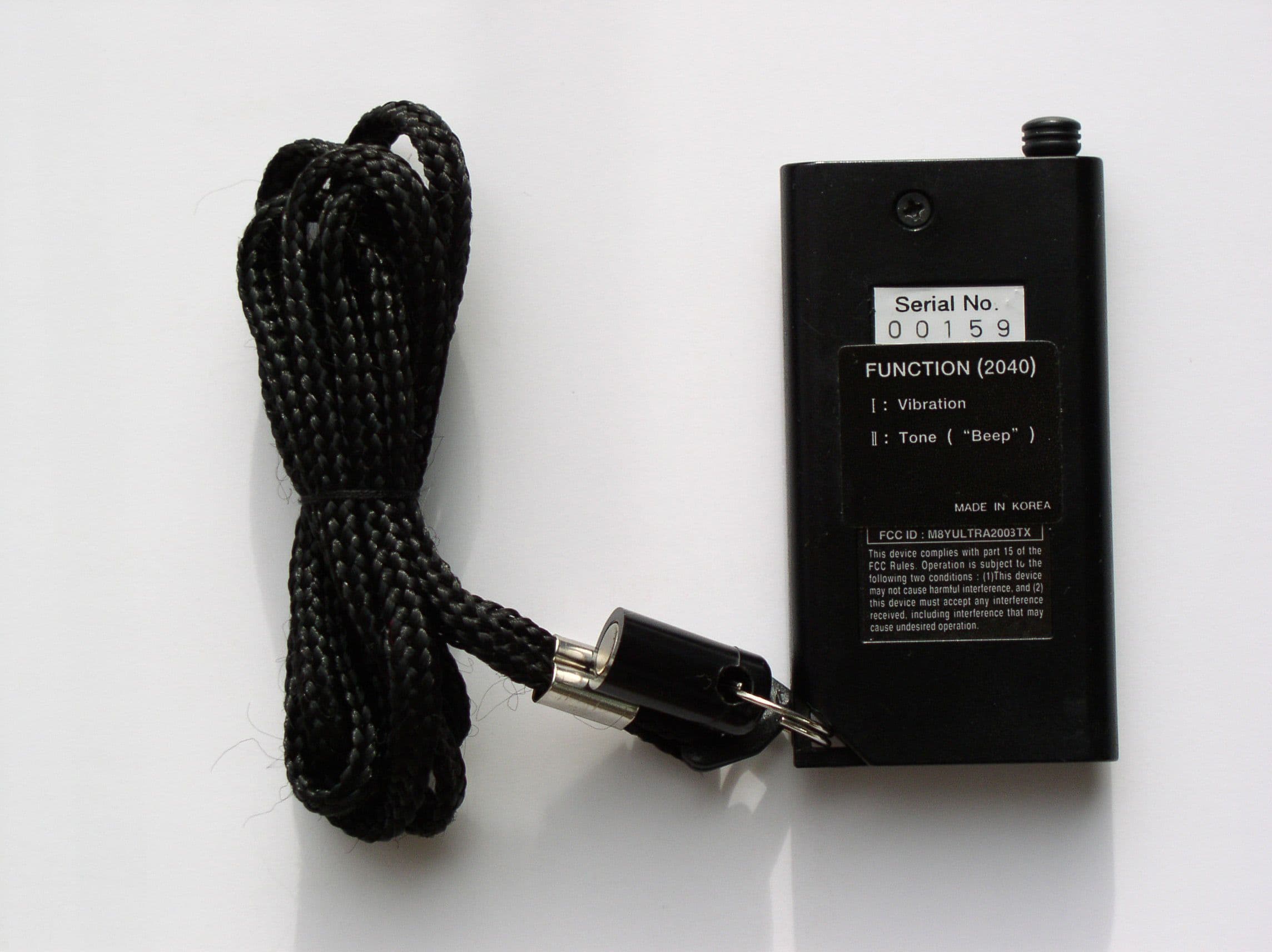
M8YULTRA2003TX
Feb 02, 2003Dog Collars
Equipment Class
DSC - Part 15 Security/Remote Control Transmitter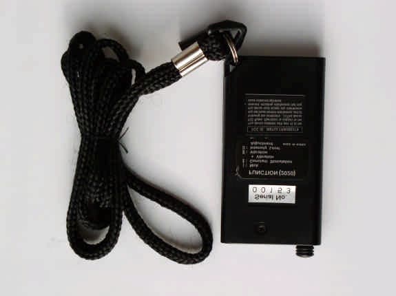
M8YULTRA2002TX
Feb 02, 2003Dog Collars
Equipment Class
DSC - Part 15 Security/Remote Control Transmitter
M8YULTRA2000TX
Aug 23, 2001Dog Collars
Equipment Class
DSC - Part 15 Security/Remote Control Transmitter
M8YULTRA2001TX
Aug 13, 2001Dog Collars
Equipment Class
DSC - Part 15 Security/Remote Control Transmitter