M8YULTRA2002TXDog Collars
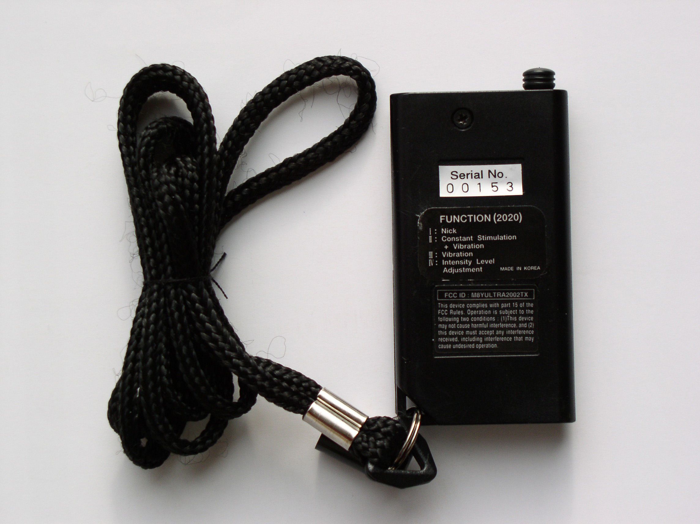
DT Systems Inc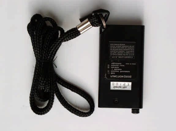
Click to zoom
Application Details
- Equipment Class
- DSC - Part 15 Security/Remote Control Transmitter
- Date of Grant
- Feb 02, 2003
- Application Purpose
- Original Equipment
- Date of Application
- Feb 02, 2003
- Equipment Note
- Dog Collars
- Frequency Range
- 308.00000000 - 308.00000000
- Company
- DT Systems Inc
- Country
- United States
Documents & Files
Document Text
Text extracted from the exhibit documents filed with the FCC. Open a document above to read the original.
Cover Letter(s)
From: Jeong-Min Kim [[email protected]] Sent: Sunday, February 02, 2003 11:52 PM To: Mike Kuo Subject: Re: D.T.Systems Inc., FCC ID:M8YULTRA2002TX, AN03T2573 Renewed test report. ************************************************ Jeong-Min Kim Tel. 82-2-860-1464 Fax. 82-2-860-1468 Mobile 82-19-226-8336 Senior Engineer Telecommunication Team, Korea Testing Laboratory 222-13, Guro-dong, Guro-ku, Seoul, 152-848, Korea e-mail: [email protected] ************************************************ ----- Original Message ----- From: "Mike Kuo" <[email protected]> To: <[email protected]> Sent: Friday, January 31, 2003 8:50 AM Subject: FW: D.T.Systems Inc., FCC ID:M8YULTRA2002TX, AN03T2573 > > > -----Original Message----- > From: CERTADM > Sent: Thursday, January 30, 2003 3:27 PM > To: '[email protected]' > Subject: D.T.Systems Inc., FCC ID:M8YULTRA2002TX, AN03T2573 > > > Notice_content > ------------- > Question #1: Per section 13.1.4.1 of ANSI C63.4, for handheld device, the > investigation shall be done with investigation of three orthogonal axes. > There is no indication in the test report that such procedure was followed. > Please explain. > > Question #2: For pulse modulation, the Average reading=Peak + 20log (M%). > M% is the max. duty cycle in 0.1 second period including blanking period ( > 15.35( c ) ). M%=(((T x N )+(t x n ))/56.2) x 100%. N: is the number of T > and n is the number of t. The sample calculation indicated in the test > report to obtain the average reading is not correct. Please correct your > tabular data. > > For your information, if the peak reading is below the average limits, you > do not need to use duty cycle correction to obtain average reading. > > Best Regards > > > Mike Kuo > The items indicated above must be submitted before processing can continue > on the above referenced application. Failure to provide the requested > information within 60 days of the original e-mail date may result in > application dismissal and forfeiture of the filing fee. Also, please note > that partial responses increase processing time and should not be submitted. > Any questions about the content of this correspondence should be directed to > the e-mail address listed below the name of the sender. >
Operational Description
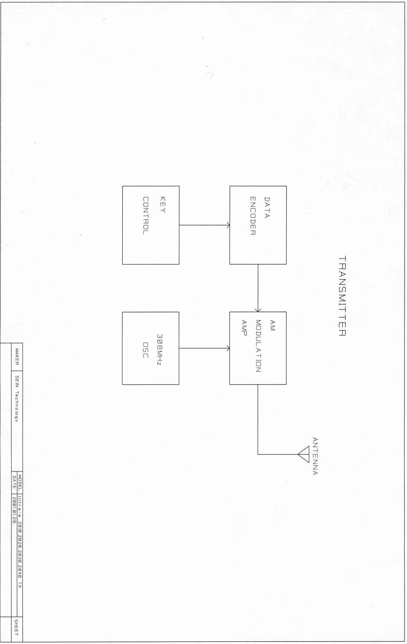
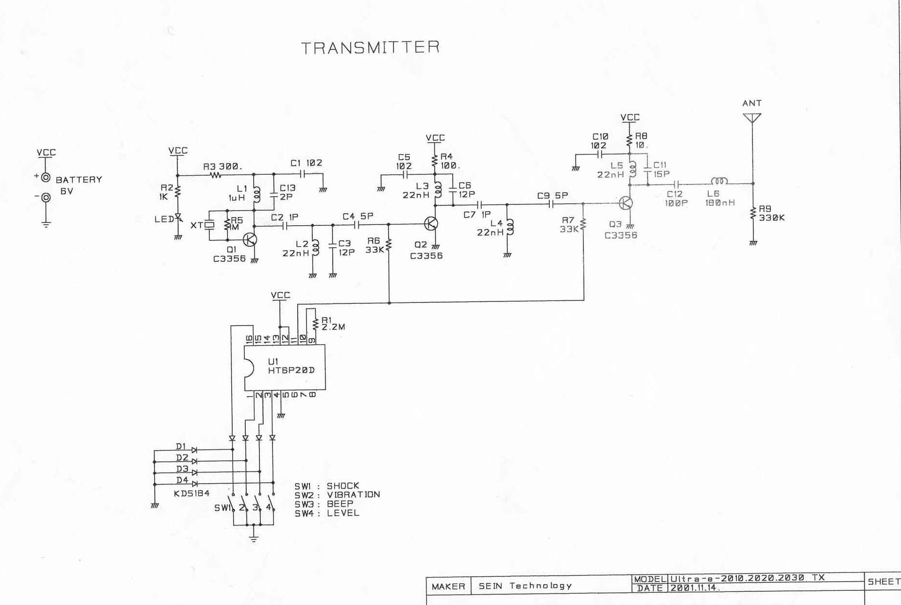
Circuit Description of Transmitter(TX) (Ultra-e-2020) Pushing one of 4 switches(SW1, SW2, SW3, SW4) on transmitter, voltage at the base of Transistor(Q1) is dropped and power is supplied into the RF Circuit(Q2, Q3). At the same time, carrier frequency(308MHz) is generated by Crystal(XT) in the Oscillation Circuit. This carrier frequency is going into Modulation Circuit through Condensor(C13) which mixes up and modulates the carrier frequency and pluse coded signal supplied from Encorder(U1). This mixed up and modulated signal enter into Antenna Circuit which emits the carrier frequency through Matching Coil(L5) in the air. The coding specification of Encorder IC is as following.
Test Report
KTL Korea Testing Laboratory Page 1 of 14 TEST REPORT This test report only responds to the tested sample and shall not be reproduced except in full without written approval of the Korea Testing Laboratory. Tested and reported by Reviewed by Jeong-Min Kim , Senior Engineer Hee-Soo Kim, EMC Team Leader KOREA TESTING LABORATORY FG101-01-02-00 222-13, Guro-Dong Guro-Gu Seoul Korea 152-053 http://www.ktl.re.kr Ref. Report No. 02-341-053 Name and address of the applicant D.T. Systems, Inc. 2872, Walnut Hill Lane, Dallas, TX 75229, USA Standard / Test regulation FCC Part 15, Subpart C Test result Pass Incoming date : December 11, 2002 Test item(s) ; Security/Remote Control Transmitter (Dog Collars) Model/type ref. ; Ultra-e-2020 Manufacturer ; EUN KI Trading Co., Ltd. Additional information ; - Required Authorization : Certification - FCC ID. : M8YULTRA2002TX - The receiver for this unit has been granted.(FCC ID.: M8YULTRA2000RX) Test date:December 162002 Issue date :December 172002 Ref. Report No. 02-341-053 Page 2 of 14 TABLE OF CONTENTS I. GENERAL INFORMATION.......................................................................................3 1. Grantee’s Name and Mailing Address 2. Manufacturer's Name and Mailing Address 3. Equipment Descriptions 4. Rules and Regulations 5. Measuring Procedure 6. Date of Measurement . GENERAL REQUIREMENTS OF THE EUT..................................................................4 1. Labelling Requirement (Section 15.19) 2. Information to User (Sections 15.21) 3. Special Accessories (Section 15.27) 4. Compliant Conditions (Section 15.231) . RADIATED EMISSION MEASUREMENT (Section 15.231)...........................................6-12 1. Test Procedure 2. Photograph of the test configuration 3. Sample Calculation 4. Measurement Data 5. Reference Data . OCCUPIED BANDWIDTH MEASUREMENT (Section 15.231)..........................................13 . TEST EQUIPMENTS USED FOR MEASUREMENT.......................................................14 Ref. Report No. 02-341-053 Page 3 of 14 . GENERAL INFORMATION 1. Grantee’s Name and : D.T. Systems, Inc. Mailing Address 2872, Walnut Hill Lane, Dallas, TX 75229 U.S.A. 2. Manufacturer's Name and : EUN KI Trading Co., Ltd. Mailing Address 1104-15, Mansu-Dong, Namdong-Ku, Incheon, 405-869, Korea 3. Equipment Descriptions 3.1 Operating Frequency : 308 MHz 3.2 Type of Emission : Pulse Code Signal 3.3 Oscillator Used : 308 MHz (Resonator) 3.4 Power Supply : DC 6 V(Battery) 4. Rules and Regulations : FCC Part 15, Subpart C 5. Measuring Procedure : ANSI C63.4-1992 6. Place of Measurement : Absorber-lined Room (KTL) 7. Date of Measurement 7.1 Line Conducted : Not Applicable 7.2 Radiated Emission : December 16, 2002 Ref. Report No. 02-341-053 Page 4 of 14 . GENERAL REQUIREMENTS OF THE EUT 1. Labelling Requirement (Section 15.19) This device complies with Part 15 of the FCC Rules. Operation is subject to the following two conditions: (1) this device may not cause harmful interface, and (2) this device must accept any interference received, including interference that may cause undesired operation. 1.1 Location of Label : Bottom side of EUT 1.2 How Applied : By Ink-Printing on Adhesive Label 2. Information to User (Section 15.21) The following or similar statements were provided in the manual for user instruction. Please refer page 19 of the attached manual for details. CAUTION : Any changes or modifications in construction of this device which are not expressly approved by the party responsible for compliance could void the user's authority to operate the equipment. 3. Special Accessories (Section 15.27) 3.1 Were the special Accessories provided? [ ] yes, [ x ] no 3.2 If yes, details for the special accessories are as follows : 3.3 If yes, were the appropriate instructions provided on the first page of the text concerned with the device? [ ] yes, [ ] no 3.4 Are these accessories provided of the type which can be readily obtained from multiple retail outlets ? [ ] yes, [ ] no And therefore does the manual specify what additional components or accessories are required to used in order to comply with the Rules? [ ] yes, [ ] no Ref. Report No. 02-341-053 Page 5 of 14 4. Compliant Conditions (Section 15.231) 4.1 Was the EUT used for continuous transmissions, such as voice or video, and data transmission ? [ ] yes, [ x ] no 4.2 Was the EUT manually operated ? [ x ] yes, [ ] no If yes, did the EUT employ a switch that would automatically deactivate the transmitter within not more than 5 seconds of being released ? [ x ] yes, [ ] no 4.3 Was the EUT automatically activated ? [ ] yes, [ x ] no If yes, did the EUT cease transmission within 5 seconds after deactivation ? [ ] yes, [ ] no 4.4 Was the EUT used for periodic transmissions at regular predetermined intervals ? [ ] yes, [ x ] no Ref. Report No. 02-341-053 Page 6 of 14 . RADIATED EMISSION MEASUREMENT (Section 15.231) 1. Test Procedure 1.1 Preliminary Testing for Reference Preliminary testing was performed in a KTL absorber-lined room to determine the emission characteristics of the EUT. The EUT was placed on the wooden table which has dimensions of 0.8 meters in height, 1 meter in length and 1.5 meters in width. Receiving antenna (Biconical antenna : 30 to 300 MHz, Log-periodic antenna : 200 to 1000 MHz or Horn Antenna : 1 to 18 GHz) was placed at the distance of 1 meter from the EUT. An attempt was made to maximize the emission level with the various configurations of the EUT. Emission levels from the EUT with various configurations were examined on a spectrum analyzer connected with a RF amplifier and graphed by a plotter. 1.2 Final Radiated Emission Test at an Absorber-Lined Room The final measurement of radiated field strength was carried out in a KTL absorber-lined Room that was listed up at FCC according to the "Radiated Emissions Testing" procedure specified by ANSI C63.4. Based on the test results in preliminary test, measurement was made in same test set up and configu…
Text truncated - open the document above for the full version.
Test Setup Photos
Ref. Report No. 02-341-053 Page 7 of 14 2. Photograph of the test configuration 3. Sample Calculation The measured field strength was determined by averaging one complete pulse train including blanking interval because the pulse repetition time of the EUT(=56.2ms) does not exceeds 0.1 seconds (15.35(c)). See graphs of page 12 . With the resolution bandwidth set at 10 kHz, the EUT produces a pulse spectrum on the spectrum analyzer because the bandwidth of the analyzer is greater than or equal to the PRF (= 641 Hz ). Therefore, as mentioned in HP Application Note 150-2 (page 11), the pulse desensitization( p ) equals zero and the display amplitude is essentially a peak level.
Contact Information
Applicant
Bryant Kim(VP)
Test Firm
Korea Testing LaboratoryJeong-Min Kim
Technical Specifications
| # | Rule Parts | Frequency Range | Power Output |
|---|---|---|---|
| 1 | 15.231 | 308 MHz - 308 MHz | - |
Other Applications from DT Systems Inc
M8YRAPT
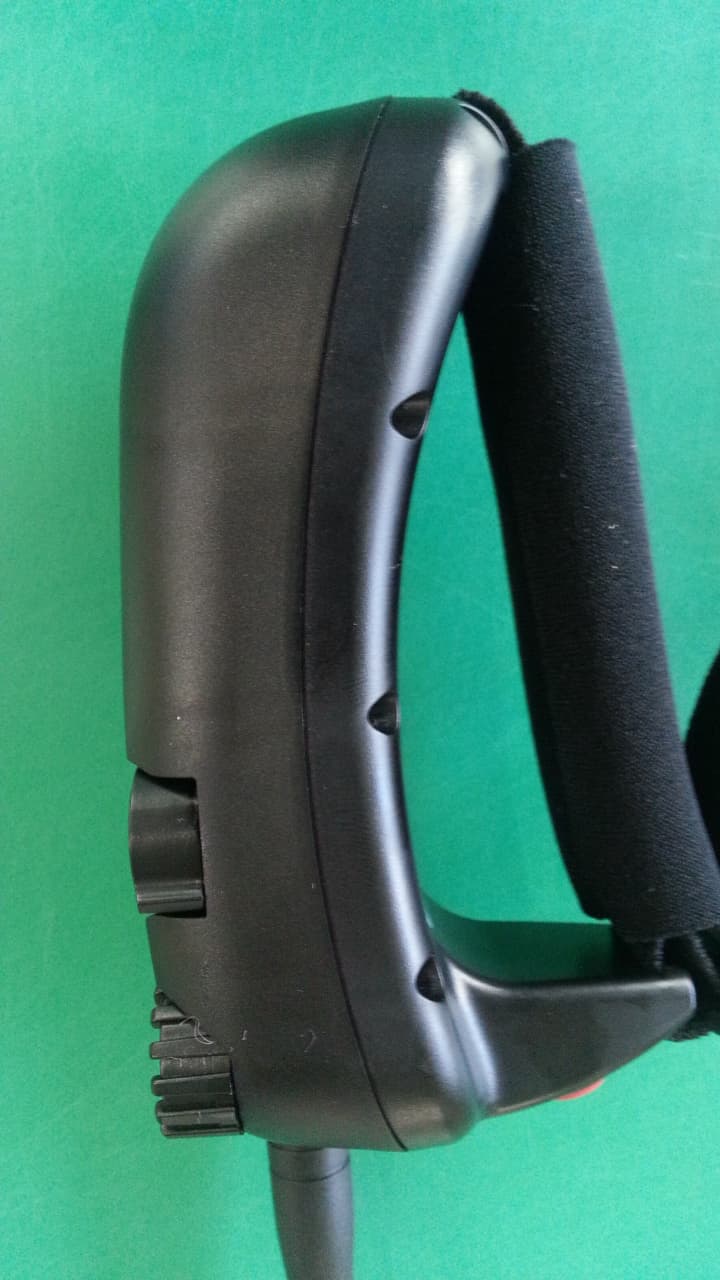
Jan 12, 2014remote control for a canine training collar
Equipment Class
DXX - Part 15 Low Power Communication Device Transmitter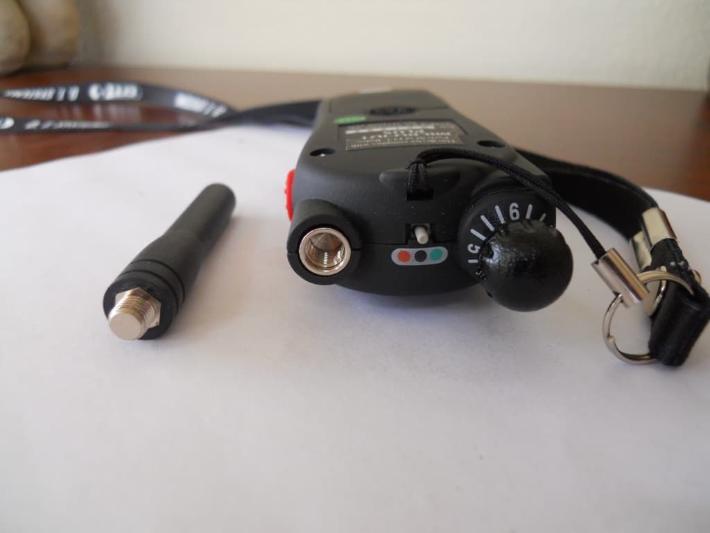
M8YIDT
Jun 09, 2010Electronic Dog Trainer
Equipment Class
DXX - Part 15 Low Power Communication Device Transmitter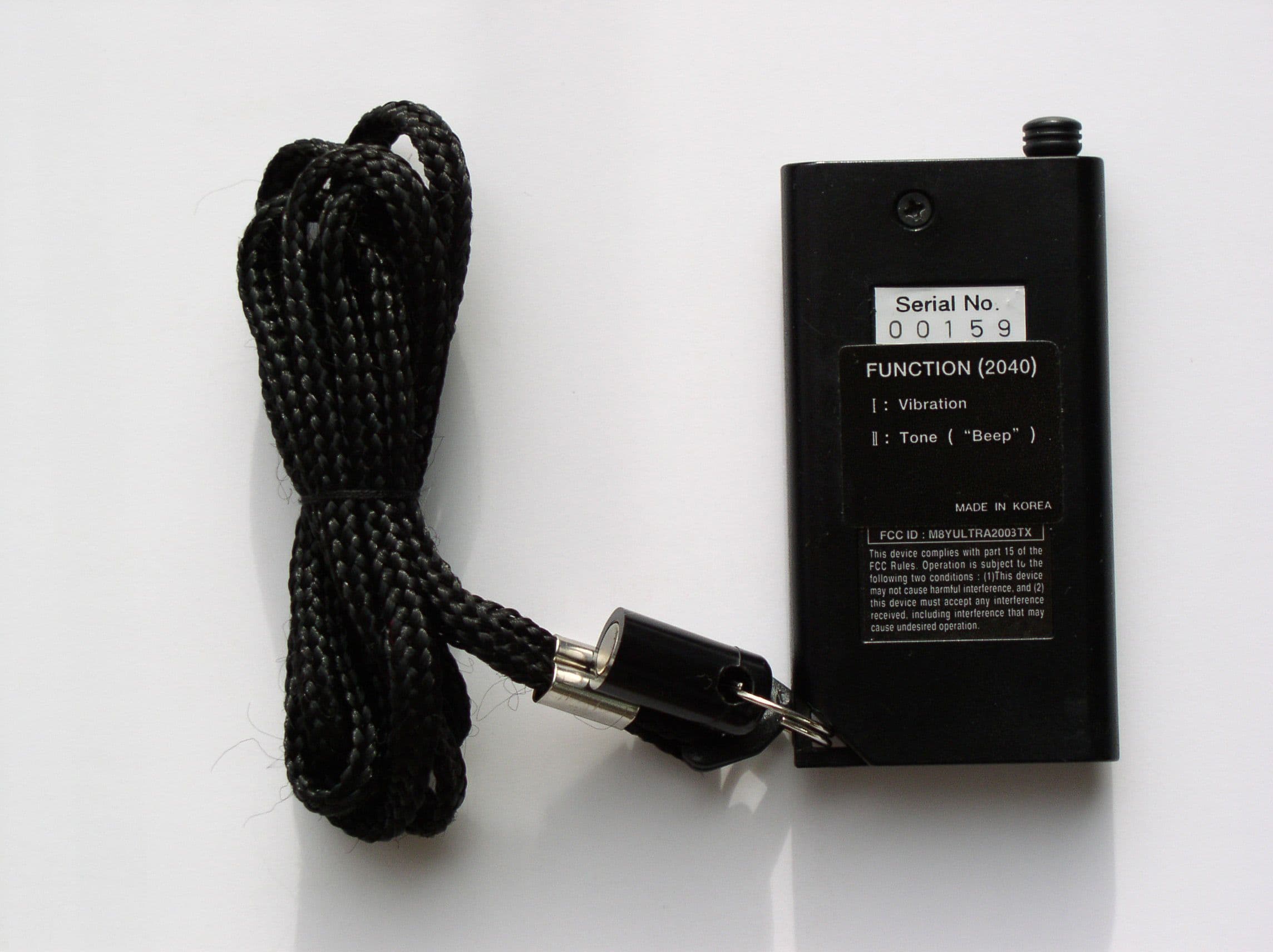
M8YULTRA2003TX
Feb 02, 2003Dog Collars
Equipment Class
DSC - Part 15 Security/Remote Control Transmitter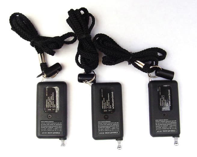
M8YULTRA2000TX
Aug 23, 2001Dog Collars
Equipment Class
DSC - Part 15 Security/Remote Control Transmitter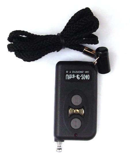
M8YULTRA2001TX
Aug 13, 2001Dog Collars
Equipment Class
DSC - Part 15 Security/Remote Control Transmitter