MCI-3775.7GHz Wireless LAN
RadioLAN Marketing Group, Inc.
Click to zoom
Application Details
- Equipment Class
- DTS - Digital Transmission System
- Date of Grant
- Nov 24, 2002
- Application Purpose
- Original Equipment
- Date of Application
- Nov 24, 2002
- Equipment Note
- 5.7GHz Wireless LAN
- Frequency Range
- 5775.00000000 - 5775.00000000
- Country
- United States
Documents & Files
Document Text
Text extracted from the exhibit documents filed with the FCC. Open a document above to read the original.
Users Manual
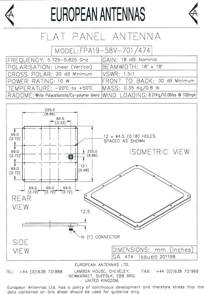
892-010 - 09/02 © 2001 RadioLAN Marketing Group, Inc. All Rights Reserved. Wireless Local Area Network Campus BridgeLINK-II™ Quick Installation Guide Campus BridgeLINK-II Quick Installation Guide Page i © 2002 – RadioLAN – All rights reserved Notices This equipment has been tested and found to comply with the limits for a Class B digital device, pursuant to Part 15 of the FCC rules. These limits are designed to provide reasonable protection against harmful interference in a residential installation. This equipment generates, uses, and can radiate radio frequency energy and, if not installed and used in accordance with the instructions, may cause harmful interference to radio communications. However, there is no guarantee that interference will not occur in a particular installation. If this equipment does cause harmful interference to radio or television reception, which can be determined by turning the equipment off and on, the user is encouraged to try to correct the interference by one of the following measures: • Reorient or relocate the receiving antenna. • Increase the separation between the equipment and receiver. • Connect the equipment into an outlet on a circuit different from that to which the receiver is connected. • Consult the dealer or an experienced radio/TV technician for help. FCC ID: MCI-377 FCC Rule Part(s): 15.247 AND 15.407 Frequency: 5.15-5.25, 5.25-5.35, and and 5.725-5.875 GHz Equipment Class: Low Power Communication Device Transmitter Output Power: 50 mW Notes: This device complies with Part 15 of FCC rules. Operation is subject to the following two conditions: 1) this device may not cause harmful interference, and 2) this device must accept any interference received, including interference that may cause undesired operation. All interface cables must be shielded. This device has shown compliance with new rules adopted under Dockets 87-389, 99-231, and 02-151 and is not affected by the Section 15.37, transition rule. Each radio is marked with its operating frequency. Campus BridgeLINK-II Quick Installation Guide Page ii © 2002 – RadioLAN – All rights reserved FCC regulations require that a person knowledgeable in electronics and trained in the correct installation of this device professionally install this device. Professional installers have a responsibility to comply with FCC part 15 rules on antenna limits and amplification. Unauthorized modifications to the device could void the End-users authority to operate it. This Product has been certified with the following antennas, and may only be used with antennas by the same manufacturer and with the same or less gain: Antenna Model Max_Gain European Antennas FPA19-58V-701/474 18 dBi RadioWaves Sector antenna SEC-5H-90CS 18 dBi RadioWaves Parabolic Dish Antennas SP4-5.8 34.8 dBi Telex Yagi Antennas 5816AB 16.5 dBi 1 Campus BridgeLINK-II Quick Installation Guide Page 1 © 2002 – RadioLAN – All rights reserved Welcome to wireless networking. The Campus BridgeLINK-II (CBL-II) is a module, which connects or bridges two 10BaseT wired networks, located in different buildings, together using a 10BaseRadio wireless link. RadioLAN allows you to connect two buildings, which are up to 1 mile (1.6 km) apart, using a Campus BridgeLINK-II™ Processor Unit (CPU), a Companion Radio Module (CRM), and a 8.86 inch square directional antenna with a 19° angle of operation, for each building link. When using the CBL-II application, you need only install the components at each building, aim the antennas toward one another, and power the system on. Quick Setup This document provides the simple steps required to install and setup the CBL-II. Please see the Campus BridgeLINK-II Users Manual located on the RMG website for more specific information. For a fast, successful installation, find a location that: • has a non-switched electrical outlet. • has access to the Ethernet backbone: • is within range of the distant CBL-II Figure 1: Campus BridgeLINK-II Bridge Processor Unit 2 Campus BridgeLINK-II Quick Installation Guide Page 2 © 2002 – RadioLAN – All rights reserved Assigning an IP Address to the CPU You need an IP address to use the CBL-II’s Web Management features. There are two ways to assign the CPU an IP Address for the TCP/IP Network. RadioLAN provides a utility called IPASSIGN, or you may use the Serial Port on the BBL. Assigning an IP Address using the Serial Port 1. Connect the CPU to a VT-100 terminal or a PC running terminal emulation software. Set up the terminal with the following settings: 9600 bits per second, 8 data bits, no parity, 1 stop bit, and no flow control. 2. Connect a standard DB-9 serial cable (not included) between a COM port on the terminal or PC and the CPU’s DB-9 serial port, and power on the CPU. You will see a series of tests then a logon screen. Initially there is no password, so press Enter. 3. Arrow down to System Configuration, and press Enter. 4. Arrow down to IP Parameters, and press Enter. 5. Enter the IP Address, Subnet Mask, and Default Gateway IP Address. 6. Next, highlight DHCP Operation Mode. Press Enter until the Disabled is displayed. 7. Press Backspace to go to the previous screen. Arrow down to Configuration Changes, and press Enter. 8. Choose “Save Configuration Changes”, and press Enter twice. The CPU will reset using the new IP address. You may also use this same serial connection to configure and manage the CPU. See the manual for more information. 3 Campus BridgeLINK-II Quick Installation Guide Page 3 © 2002 – RadioLAN – All rights reserved Preparing a PC to use IPASSIGN This utility allows you to assign an IP address to the CPU using a PC with a 10BaseT-network interface card installed. Note: The PC must not be operating a DHCP server during this procedure. The CPU supports connection to the network by way of a standard 10BaseT Ethernet Cable, which is typically used for connection to a hub, or a Crossover Cable, which is typically used for connection directly to a PC network interfac…
Text truncated - open the document above for the full version.
Cover Letter(s)
tel: 650-726-1263 fax: 650-726-1252 [email protected] Thomas N. Cokenias EMC &Radio Approvals Test & Consulting Services for Commercial, Military, International Compliance P.O. Box 1086 El Granada, CA 94018 FCC Laboratory 15 Sept 2002 7435 Oakland Mills Road Columbia, MD 21046 Attention: Application Examiner Reviewing Engineer Applicant: RadioLAN Marketing Group FCC ID: MCI-387 and FCC ID:MCI-377 To whom it may concern, Request is hereby submitted, on behalf of my client RadioLAN to withhold from public review certain portions of the application for equipment certification for the referenced FCC identifier. In particular, the following sections of the application and report are requested to be kept confidential: Block Diagrams Schematic Operational Description Rationale for request for confidentiality: RadioLAN has invested considerable time and materials in research and development to produce the referenced product. Disclosure of the confidential portions of this application to competitors would give them competitive advantage in developing similar products. If you have questions or need further information, please contact the undersigned. Sincerely, tel: 650-726-1263 fax: 650-726-1252 [email protected] THOMAS N. COKENIAS EMC Consultant/Agent for RadioLAN Marketing Group
Cover Letter(s)
From: Tom Cokenias [[email protected]] Sent: Thursday, November 14, 2002 8:45 PM To: Mike Kuo Subject: Re: FW: RadioLAN Marketing Group, Inc., FCC ID:MCI-377, AN02t2275 Mike, Here are answers to your questions: ANS1 These are the point to point antennas: RadioWaves Parabolic Dish Antennas SP4-5.8 34.8 dBi ANS2 I made corrections to test report, MPE info, and user manual. Attached are corrected corrected documents. ANS3 The antenna data sheets are attached. The user manual, spec sheets, and reports are now consistent with each other. ANS4 Pulse position modulation means that the carrier is turned ON and OFF at different times. The amplitude of each (very short) pulse is equal to the peak amplitude of the TX output. Because pulses are only a few nanoseconds in length and are separated from each other by nanoseconds, it is difficult to make peak power measurements when the EUT is transmitting pulse modulated signals. Since it is possible to turn off the pulsing function of the transmitter, the peak output of the transmitter has been determined to be 18 dBm. This is a standard method of making measurement for this type of product - page 13 of the attached TCB training document seems to permit this, and it is consistent with pulse measurement techniques in HP Application Note 150, and I hope you will be able to accept the measurement as it was presented. -----Original Message----- From: CERTADM Sent: Thursday, October 31, 2002 1:41 PM To: '[email protected]' Subject: RadioLAN Marketing Group, Inc., FCC ID:MCI-377, AN02t2275 Notice_content ------------- Question #1: Page 1 of 12 of test report listed four antennas that will be used. Please specify which antenna will be used for point-to-point. Question #2: The antenna specification listed in the test report does not agree with those antenna listed in the user manual. Please explain. Question #3: Please provide antenna specification for European Antenna, Telex and 4 ft dish. The 4ft dish antenna specification provided does not agree with the specification listed in the test report. Question #4: The RBW used in the conducted output power test is 1MHz. The 6dB bandwidth measured for this device is 26MHz. Per FCC measurement guideline in measuring the spread spectrum device, the RBW shall be greater than 6dB BW. Please redo the conducted output power tests and provide the test data. Best Regards Mike Kuo / TCB Certifier The items indicated above must be submitted before processing can continue on the above referenced application. Failure to provide the requested information within 60 days of the original e-mail date may result in application dismissal and forfeiture of the filing fee. Also, please note that partial responses increase processing time and should not be submitted. Any questions about the content of this correspondence should be directed to the e-mail address listed below the name of the sender.
Cover Letter(s)
Description of RadioLAN Product Similarities FCC ID: MCI-387 FCC ID: MCI-377 plastic enclosure The two products use the same electronics, with the exception that the 387 is limited to the EA panel antenna only. Antenna conducted data is taken at the antenna output of the CRM, and is applicable to both products. The radiated and AC line conducted data taken for one product is applicable to both units. The same schematics, block diagrams, and theory of operation are applicable to both products. Campus BridgeLINK-II 15.247 DTS 5.775 GHz radio box (CRM) various antennas: yagi, dish, flat panel Campus BridgeLINK-II 15.247 DTS 5.775 GHz radio box (CRM) Panel Antenna only LAN AC/DC AC mains LAN AC/DC AC Mains
External Photos
Product Photographs Applicant: RadioLAN Marketing Group FCC ID: MCI-377 Radio Unit Product Photographs Applicant: RadioLAN Marketing Group FCC ID: MCI-377 Radio Unit
External Photos
Product Photographs Applicant: RadioLAN Marketing Group FCC ID: MCI-377 IDU Product Photographs Applicant: RadioLAN Marketing Group FCC ID: MCI-377 IDU Product Photographs Applicant: RadioLAN Marketing Group FCC ID: MCI-377 IDU Product Photographs Applicant: RadioLAN Marketing Group FCC ID: MCI-377 IDU
ID Label/Location Info
FCC ID Label and Label location Applicant: RadioLAN Marketing Group FCC ID: MCI-377 FCC ID: MCI-377 This device complies with Part 15 of the FCC Rules. Operation is subject to the following two conditions: (1) This device may not cause harmful interference, and (2) This device must accept any interference received, including interference than may cause undesired operation
Internal Photos
Product Photographs Applicant: RadioLAN Marketing Group FCC ID: MCI-377 Radio Unit Product Photographs Applicant: RadioLAN Marketing Group FCC ID: MCI-377 Radio Unit Product Photographs Applicant: RadioLAN Marketing Group FCC ID: MCI-377 Radio Unit Product Photographs Applicant: RadioLAN Marketing Group FCC ID: MCI-377 Radio Unit Product Photographs Applicant: RadioLAN Marketing Group FCC ID: MCI-377 Radio Unit Product Photographs Applicant: RadioLAN Marketing Group FCC ID: MCI-377 Radio Unit
Internal Photos
Product Photographs Applicant: RadioLAN Marketing Group FCC ID: MCI-377 IDU Product Photographs Applicant: RadioLAN Marketing Group FCC ID: MCI-377 IDU
Parts List/Tune Up Info
ModelFrequency,PolarizationGainBeamwidth °X-Pol.F/B RatioVSWR, Max NumberGHzdBi (nominal) -3dBRejection, dBdB(R.L., dB) 5.725 - 5.850 GHZ PARABOLICSUBSCRIBERANTENNAS FEATURES nAntenna diameters: • 1′(30 cm) • 1.5′(45 cm) • 2′(60 cm) • 3′(90 cm) • 4′(120 cm) • 6′(180 cm) nAntenna weights: • 1′15 lbs. (6.8kg) • 1.5′18 lbs. (8.3kg) • 2′22 lbs. (9.9kg) • 3′35 lbs. (15.8kg) • 4′60 lbs. (27.0kg) • 6′90 lbs. (40.5kg) nLightweight and rugged design nEasily installed nRF Connector Interface: Type “N” female nStandard color white: other colors available on request nRadome standard for 1′and 1.5′models, optional for all other models nDual Polarity models also available ELECTRICALSPECIFICATIONS(typical performance)* SP1-5.85.725 - 5.850Single22.511.7 17301.5:1 (14.0) SP1.5-5.85.725 - 5.850Single25.78.020311.5:1 (14.0) SP2-5.85.725 - 5.850Single28.56.228361.5:1 (14.0) SP3-5.85.725 - 5.850Single31.44.230381.5:1 (14.0) SP4-5.85.725 - 5.850Single34.83.030421.5:1 (14.0) SP6-5.85.725 - 5.850Single37.92.030441.5:1 (14.0) * All specifications subject to change without notice. Radio Waves, Inc. http://www.radiowavesinc.com
Parts List/Tune Up Info
90- Degree 5.725 - 5.850 GHz Sector Antenna Frequency, GHz Polarization Gain, dBi (nominal) Beamwidth -3dB Azimuth, deg. Elevation, deg. X-Pol. Rejection, dB Isolation btw ports, dB F/B Ratio, dB VSWR, Max (R.L., dB) RF Interface Note: Product specifications may change without notice. For greater F/B ratio consult factory. Electrical Specifications, typical Key Features •Flat panel design offers low windloads. •Lightweight and rugged design is easily installed. •Dimensions: Low Gain model: 25.5 x 8.5 x 7.5 inches High Gain model: 41.5 x 8.5 x 7.5 inches Dual-pol model: 41.5 x 8.5 x 7.5 inches •Connector Interface: Type “N” female. •Polarization: • Plane Polarized (Horizontal or Vertical) • Dual Polarized (Horizontal & Vertical) •Standard antenna mount accommodates a 2.5 in. to 4.5 in. diameter pipe. Optional 15 degree mechanical downtilt. Model # Radio Waves, Inc. • 495 R Billerica Avenue • N. Billerica, MA 01862 USA • Tel: (978) 459-8800 • Fax: (978) 459-8814 www.radiowavesinc.com • E-mail: [email protected] DSSEC-5.7-90 Rev.D 5.725 - 5.850 Vertical 16.0 90 8 25 >25 1.5:1 (14.0) “N” (F) 5.725 - 5.850 Horizontal 16.0 90 8 25 >25 1.5:1 (14.0) “N” (F) SEC-5V-16-90SEC-5H-16-90SEC-5D-16-90 5.725 - 5.850 Dual 16.0 90 8 25 20 >25 1.5:1 (14.0) “N” (F) SEC-5H-18-90 5.725 - 5.850 Horizontal 18.0 90 4 25 >25 1.5:1 (14.0) “N” (F) SEC-5V-18-90 5.725 - 5.850 Vertical 18.0 90 4 25 >25 1.5:1 (14.0) “N” (F)
Parts List/Tune Up Info
Telex ® TechnicalData 5.8 GHz WLAN/UNII Directional Antenna 5.725 - 5.825 GHz Order No. 5816AB Specifications Electrical: Frequency Range . . . . . . . . . . . . . . . . . . . . . . . . . . . . . . . . . . . . . . . . . . . . . . . . . . . . . . . . . . . . . . 5725-5825 MHz VSWR . . . . . . . . . . . . . . . . . . . . . . . . . . . . . . . . . . . . . . . . . . . . . . . . . . . . . . . . . . . . Less than 2:1, 1.5:1 Nominal Nominal Impedance . . . . . . . . . . . . . . . . . . . . . . . . . . . . . . . . . . . . . . . . . . . . . . . . . . . . . . . . . . . . . . . . . . 50 ohms Gain . . . . . . . . . . . . . . . . . . . . . . . . . . . . . . . . . . . . . . . . . . . . . . . . . . . . . . . . . . . . . . . . . . . . . . 16.5 dBi Nominal Front-to-Back ratio . . . . . . . . . . . . . . . . . . . . . . . . . . . . . . . . . . . . . . . . . . . . . . . . . . . . . . . . Greater than 20 dB Half-power Beamwidth . . . . . . . . . . . . . . . . . . . . . . . . . . . . . . . . . . . . . . . . . . . . . . . . . . . . . . . . . . . . . 19 degrees Polarization . . . . . . . . . . . . . . . . . . . . . . . . . . . . . . . . . . . . . . . . . . . . . . . . . . . . . . . . . . . . . . . . . . . . . . . . . Vertical Mechanical: Size . . . . . . . . . . . . . . . . . . . . . . . . . . . . . . . . . . . . . . . . . . . . . . . . . . . . . . . . . . . . . . . . . . . . . . . . . . . . . 18.0” long Mounting method . . . . . . . . . . . . . . . . . . . . . . . . . . . . . . . . . . . . . . . . . . . . . . . . . . . . . . . . Clamps to vertical mast up to - 1 5/8" O.D. Cable length . . . . . . . . . . . . . . . . . . . . . . . . . . . . . . . . . . . . . . . . . . . . . . . . . . . . . . . . . . . . . . . . . . . . . . . . . . 1.5 ft Cable Type . . . . . . . . . . . . . . . . . . . . . . . . . . . . . . . . . . . . . . . . . . . . . . . . . . . . . . . . . . . . . . . LMR-195, 50 ohm low-loss, white Connector . . . . . . . . . . . . . . . . . . . . . . . . . . . . . . . . . . . . . . . . . . . . . . . . . . . . . . . . . . . . . . . . . . . . . . . Type N jack Optional connectors . . . . . . . . . . . . . . . . . . . . . . . . . . . . . . . . . . . . . . . . . . . . . . . TNC, TNC-RP, SMA, SMA-RP General Description This antenna is a totally enclosed 34 element Yagi antenna for the 5725 to 5825 MHz frequency band. It is designed to be used as a bridge antenna between two networks or for point to point communications. It has a nominal VSWR of 1.5:1 and is less than 2:1 over the entire frequency band. The gain is 16.5 dBi and the half-power beamwidth is 19 degrees. This antenna is normally mounted on a mast and is vertically polarized R 8601 East Cornhusker Highway, Lincoln, NE 68505 Phone: (402) 467-5321 FAX: (402) 467-3279 Since it is the intent of TELEX COMMUNICATIONS, INC. to continually improve its products, Telex reserves the right to make specification and design changes without notice. Printed in U.S.A. http://www.telexwireless.com August 2001
RF Exposure Info
Sheet1 RF Hazard Distance CalculationmW/cm2 from Table1: 1.00 Max RF Powe TX Antenna MPE P, dBm G, dBi Safe Distance, cm 18.0 34.8 123.1 RadioWaves 4ft dish 18.0 18.0 17.8 RadioWaves sector 18.0 16.5 15.0 Telex yagi 18.0 18.0 17.8 EA flat panel Basis of Calculations: 4 36.0 36.0 E^2/3770 = S, mW/cm2E, V/m = (Pwatts*Ggain*30)^.5/d, metersd = ((Pwatts*G*30)/3770*S))^0.5 Pwatts*Ggain = 10^(PdBm-30+GdBi)/10) NOTE: For mobile or fixed location transmitters, minimum separation distance is 20 cm, even if calculations indicate MPE distance is less Page 1
Test Report
RadioLAN page 1 of 12 FCC ID: MCI-377 1 EMISSIONS TEST REPORT FOR A LOW POWER TRANSMITTER I. GENERAL INFORMATION Requirement:Federal Communications Commissions Test Requirements: 15.205, 15.207, 15.209, 15.247 Applicant:RadioLAN Marketing Group 185 Lewis Road - Suite 30 San Jose, CA 95111 FCC ID: MCI-377 II. DESCRIPTION OF EQUIPMENT UNDER TEST (EUT) RadioLAN FCC ID: MCI-377 is a DTS transceiver in the 5,725 - 5,850 MHz band. Output power : 50 mW (17 dBm) nominal 63 mW (18dBm) maximum Center frequency: 5.775 GHz (single channel) 6 dB BW 26.6 MHz 20 dB BW: 43 MHz The product consists of the Campus BridgeLINK-II ethernet bridge processor unit , the CBL-II radio section, and one of several kinds of antennas connected to the CBL-II via N-type coaxial cable. Antennas tested with this transceiver: Antenna typeMfrModel IDGain (dBi) Flat panelEuropean AntennasFPA 19-58V18 YagiTelex5816AB16.5 SectorRadioWavesSEC-5H-90CS18 4 ft. Dish RadioWaves SP4-5.8 34.8 A separately certificated product, FCC ID: MCI-387, is an integrated unit consisting of the Campus BridgeLINK-II, CBL-II, and the EA flat panel antenna. III. TEST LOCATION All emissions tests were performed at: Compliance Certification Services 571F Monterey Road Morgan Hill, CA 95037 T.N. Cokenias15 Sept 2002 EMC Consultant/Agent for RadioLAN Marketing Group RadioLAN page 2 of 12 FCC ID: MCI-377 2 TEST PROCEDURES Radiated Emissions Test Requirement: 15.109, 15.205, 15.209, 15.247 Measurement Equipment Used: HP 8566 Spectrum Analyzer HP 8447D pre-amplifier Miteq NSP2600-44 Preamp, 1- 26 GHz HP 11975A Preamplifier, 2 - 8 GHz (used with HP11970 external mixers) Schaffner Chase Bilog antenna, 30 - 2000 MHz EMCO Double Ridge Waveguide Horn, 1 - 18 GHz Antenna Research Associates MWH 1826/B, 18 - 26.5 GHz HP 11970A Harmonic mixer, 26.5 - 40 GHz HP 11970Q Harmonic mixer, 33 - 50 GHz HP 11970V Harmonic mixer, 50 - 75 GHz HP 11970W Harmonic mixer, 75 - 110 GHz Low loss antenna cable (0.7 dB/ft @ 24 GHz) Test Set-Up external mixer spectrum analyzer leveling pre-amp -OR- HPF 1-26 GHz pre-amp .3 - 3.0 m horn antenna bilog ant. - OR - 3 meters 8566 spectrum analyzer 8447D pre-amp RadioLAN page 3 of 12 FCC ID: MCI-377 3 Test Method With the transmitter operating, the EUT was rotated 360° and the search antenna was raised and lowered in both polarities, all in an attempt to maximize the levels of the received emission for each harmonic and spurious emission up to 40 GHz. Testing was performed for each of four different types of antennas. Antenna typeMfrModel IDGain (dBi) Flat panelEuropean AntennasFPA 19-58V18 YagiTelex5816AB16.5 SectorRadioWavesSEC-5H-90CS18 4 ft. Dish RadioWaves SP4-5.8 34.8 Test Results, 1- 40 GHz Refer to test results in separate Excel spreadsheets for each antenna NOTE: For radiated emissions that fall on restricted bands per 15.205, emissions limit is 54 dBuV/m at 3 m for emissions above 960 MHz. Per 15.247(c) all other undesired emissions must be 20 dB below the highest in-band emission when measured in a 100 kHz bandwidth. From antenna conducted data below, in a 100kHz bandwidth, maximum in-band emission is 3.2 dBm 3.2 - 20 = -16.8 dBm limit, 30 - 40,000 MHz. Using the relationship between RF power, antenna gain, distance, and field strength E v/m = SQRT(Pwatts*30*Gain)/d meters converting to dB, assuming 1ft (0.3m) distance: E dBuV/m = 115.24 +P dBm+ GdBi . For strictest emission level, assume G = 0 dBi: Emax, dBuv/m = 115.24 -16.8 = 98.4 dBuV/m at 1 ft for non-restricted bands. RadioLAN page 4 of 12 FCC ID: MCI-377 4 Test Results, 30 - 1000 MHz Refer to separate Excel spreadsheet. RadioLAN page 5 of 12 FCC ID: MCI-377 5 AC Line Conducted Emissions Test Requirement: 15.107, 15.207 Measurement Equipment Used: Rohde & Schwarz EMI Receiver ESHS-20 Fischer Custom Communication LISN, FCC-LISN-50/250-25-2 Test Set-up LISN AC Power supply/data inserter Figure 2 FIM Test Procedure 1. The EUT was placed on a wooden table 40 cm from a vertical ground plane and approximately 80 cm above the horizontal ground plane on the floor. The EUT was set to transmit in normal mode. 2. Line conducted data was recorded for both NEUTRAL and HOT lines. Test Results Refer to separate graphs and tabulated data sheets. RadioLAN page 6 of 12 FCC ID: MCI-377 6 Minimum 6 dB Bandwidth Test Requirement: 15.247(a)2 Measurement Equipment Used: HP 8593EM Spectrum Analyzer 6’ length low loss coaxial cable Test Procedures The EUT was configured on a test bench. The EUT was set for continuous operation. While the transmitter broadcast a steady stream of digital data, the analyzer MAX HOLD function was used to capture the envelope of the transmission occupied bandwidth. Test Results: Refer to attached spectrum analyzer charts. Data taken with RES BW of 100 kHz shows minimum 6 dB BW of 26.6MHz. RadioLAN page 7 of 12 FCC ID: MCI-377 7 Minimum 6 dB Bandwidth RadioLAN page 8 of 12 FCC ID: MCI-377 8 RF Power Output Test Requirement:15.247(b) Measurement Equipment Used: HP 8566B Spectrum Analyzer 2 ft low loss RF cable Test Procedures 1. The EUT was configured on a test bench. 2. The pulse position modulation of the EUT was disabled. Pulse position modulation is achieved by switching RF output ON and OFF in a pre-determined time sequence. When the modulation is turned off, the resulting CW signal is the peak power output of the transmitter. Test Results Maximum output power is 18 dBm. Refer to attached spectrum analyzer chart. RadioLAN page 9 of 12 FCC ID: MCI-377 9 Spurious Emissions, Conducted Test Requirement: 15.247(c) Measurement Equipment Used: HP 8566 Spectrum Analyzer 2 ft length low loss A coaxial RF cable Test Procedure 1. The EUT was configured on a test bench. The cable was connected between the EUT antenna port and the spectrum analyzer input port. Spectrum analyzer RES BW was set to 100 kHz. While the transmitter broadcast a steady stream of digital data, the analyzer MAX HOLD function was used to capture the envelope of the transmission. Readings were taken out to …
Text truncated - open the document above for the full version.
Test Report
FCC ID: OEWCX-DS3-58G 07/26/02 FCC Measurement Compliance Certification Services, Morgan Hill Open Field Site Test Engr: T.Nguyen Project #: 02U1321-1 Company: RadioLAN Marketing Group EUT Descrip.: 5.775 GHz Point to Point DTS Transceiver ("Trinidad") FCC ID: MCI-387 Test Target: 15.205, 15.209, Equipment for 1-22 GHz: Equipment for 18 - 40 GHz: HP8566B Analyzer HP8566B Analyzer Miteq NSP2600-44 Preamp HP 11975A Amplifier (LO) EMCO 3115 Antenna HP 11970K External Mixer/ARA ARA MWH 1826/B HP 11970 External mixer/ 26.5-40 GHz horn antenna Cable: 17.0 feet Cable: IF Only (321 MHz) Peak Measurements: Average Measurements: 1 MHz Resolution Bandwidth 1MHz Resolution Bandwidth 1MHz Video Bandwidth 10Hz Video Bandwidth f Dist Read Pk Read Avg. AF CL Amp D Corr HPF Peak Avg Pk Lim Avg Lim Pk Mar Avg Mar Notes GHz feet dBuV dBuV dB/m dB dB dB dBuV/m dBuV/m dBuV/m dBuV/m dB dB 5.775 7.3 0.0 0.0 119.6 11.555 10.0 44.5 29.5 39.2 10.5 -39.7 0.1 1.0 55.7 40.7 74.0 54.0 -18.3 -13.3 2nd Harmonic, Vertical 15.205 17.325 10.0 61.1 39.7 45.0 14.2 -44.1 0.1 1.0 77.3 55.9 99.6 -22.3 55.9 -20 dB (not restricted) 23.105 1.0 45.9 35.3 32.7 17.8 -43.5 -19.9 1.0 34.0 23.4 74.0 54.0 -40.0 -30.6 4th Harmonic, Vertical (NF) 11.535 10.0 41.2 29.7 39.2 10.5 -39.6 0.1 1.0 52.4 40.9 74.0 54.0 -21.6 -13.1 2nd Harmonic, Horizonatl 15.205 17.330 10.0 58.9 35.1 45.0 14.2 -44.1 0.1 1.0 75.1 51.3 99.6 -24.5 51.3 -20 dB (not restricted) 23.105 1.0 45.9 35.3 32.7 17.8 -43.5 -19.9 1.0 34.0 23.4 74.0 54.0 -40.0 -30.6 4th Harmonic, Horizontal (NF) CONVLOSS CONV LOSS = conversion loss 28.880 1.0 43.4 35.3 37.5 -5.8 0.0 -19.9 0.0 55.2 47.1 74.0 54.0 -18.8 -6.9 of external mixers 33.250 1.0 44.0 35.3 39.1 -6.9 0.0 -19.9 0.0 56.3 47.6 74.0 54.0 -17.7 -6.4 all emissions noise floor H and V 40.000 1.0 43.4 35.3 40.3 -6.9 0.0 -19.9 0.0 56.9 48.8 74.0 54.0 -17.1 -5.2 AF calculated from 22 dBi horn gain AF=9.734/lamda*(G)^0.5lamda = wavelength, m f Measurement Frequency Amp Preamp Gain Avg Lim Average Field Strength Limit Dist Distance to Antenna D Corr Distance Correct to 3 meters Pk Lim Peak Field Strength Limit Read Analyzer Reading Avg Average Field Strength @ 3 m Avg Mar Margin vs. Average Limit AF Antenna Factor Peak Calculated Peak Field Strength Pk Mar Margin vs. Peak Limit CL Cable Loss HPF High Pass Filter 285644.XLS
Test Report
FCC ID: OEWCX-DS3-58G 05/06/02 FCC Measurement Compliance Certification Services, Morgan Hill Open Field Site Test Engr: Frank Ibrahim Project #: 02U1259-1 Company: RadioLAN Marketing Group EUT Descrip.: 5.775 GHz Point to Point DTS Transceiver, Antenna : 4' Parabolic, Model: RadioWaves 100 170-4 FCC ID: MCI-377 Test Target: 15.205, 15.209, Equipment for 1-22 GHz: Equipment for 18 - 40 GHz: HP8566B Analyzer HP8566B Analyzer Miteq NSP2600-44 Preamp HP 11975A Amplifier (LO) EMCO 3115 Antenna HP 11970K External Mixer/ARA ARA MWH 1826/B HP 11970 External mixer/ 26.5-40 GHz horn antenna Cable: 17.0 feet Cable: IF Only (321 MHz) Peak Measurements: Average Measurements: 1 MHz Resolution Bandwidth 1MHz Resolution Bandwidth 1MHz Video Bandwidth 10Hz Video Bandwidth f Dist Read Pk Read Avg. AF CL Amp D Corr HPF Peak Avg Pk Lim Avg Lim Pk Mar Avg Mar Notes GHz feet dBuV dBuV dB/m dB dB dB dBuV/m dBuV/m dBuV/m dBuV/m dB dB 5.775 7.3 0.0 0.0 119.6 11.555 10.0 44.5 29.5 39.2 10.5 -39.7 0.1 1.0 55.7 40.7 74.0 54.0 -18.3 -13.3 2nd Harmonic, Vertical 15.205 17.330 10.0 61.1 39.7 45.0 14.2 -44.1 0.1 1.0 77.3 55.9 99.6 -22.3 55.9 -20 dB (not restricted) 23.105 1.0 45.9 35.3 32.7 17.8 -43.5 -19.9 1.0 34.0 23.4 74.0 54.0 -40.0 -30.6 4th Harmonic, Vertical (NF) 11.555 10.0 41.2 29.7 39.2 10.5 -39.7 0.1 1.0 52.4 40.9 74.0 54.0 -21.6 -13.1 2nd Harmonic, Horizonatl 15.205 17.330 10.0 58.9 35.1 45.0 14.2 -44.1 0.1 1.0 75.1 51.3 99.6 -24.5 51.3 -20 dB (not restricted) 23.105 1.0 45.9 35.3 32.7 17.8 -43.5 -19.9 1.0 34.0 23.4 74.0 54.0 -40.0 -30.6 4th Harmonic, Horizontal (NF) CONVLOSS CONV LOSS = conversion loss 28.880 1.0 43.4 35.3 37.5 -5.8 0.0 -19.9 0.0 55.2 47.1 74.0 54.0 -18.8 -6.9 of external mixers 34.655 1.0 43.4 35.3 39.1 -6.9 0.0 -19.9 0.0 55.7 47.6 74.0 54.0 -18.3 -6.4 all emissions noise floor H and V 40.000 1.0 43.4 35.3 40.3 -6.9 0.0 -19.9 0.0 56.9 48.8 74.0 54.0 -17.1 -5.2 AF calculated from 22 dBi horn gain AF=9.734/lamda*(G)^0.5lamda = wavelength, m f Measurement Frequency Amp Preamp Gain Avg Lim Average Field Strength Limit Dist Distance to Antenna D Corr Distance Correct to 3 meters Pk Lim Peak Field Strength Limit Read Analyzer Reading Avg Average Field Strength @ 3 m Avg Mar Margin vs. Average Limit AF Antenna Factor Peak Calculated Peak Field Strength Pk Mar Margin vs. Peak Limit CL Cable Loss HPF High Pass Filter 285645.XLS
Test Report
Compliance Certification ServicesB-Site7/8/2002 Mike H Radiated EmissionsRadiolan FCC 15.247Transmitting with Telex 5816AB Antenna Company:RadioLAN Marketing Group EUT Descrip5.775 GHz Point to Point DTS Transceiver FCC ID:MCI-377 Equipment for 1-22 GHz:Equipment for 18 - 40 GHz: HP8566B AnalyzerHP8566B Analyzer Miteq NSP2600-44 PreampHP 11975A Amplifier (LO) EMCO 3115 AntennaHP 11970K External Mixer/ARA ARA MWH 1826/BHP 11970 External mixer/ 26.5-40 GHz horn antenna Cable17.0feetCable: IF Only (321 MHz) Peak Measurements:Average Measurements: 1 MHz Resolution Bandwidth1MHz Resolution Bandwidth 1MHz Video Bandwidth10Hz Video Bandwidth Specification Distance:3meters FreqPolDe tSAAFDist Dist Preamp Cable / HPFFieldLimitMargin GHz V/HdBuV dB/mmdBdBdBdBuV/m dBuV/mdB Note 1: RBW = 100 kHz for fundamental and spurious emissions outside restricted band…
Text truncated - open the document above for the full version.
Contact Information
Applicant
Tom Mitchell(President and CEO)
408-365-6200Fax: 408-365-7675
Test Firm
Compliance Certification Services IncSteve Cheng
Technical Specifications
| # | Rule Parts | Frequency Range | Power Output |
|---|---|---|---|
| 1 | 15C | 5.78 GHz - 5.78 GHz | 63.00 mW |
Other Applications from RadioLAN Marketing Group, Inc.

MCI-397
Jul 24, 2003Wireless Ethernet Switch
Equipment Class
DTS - Digital Transmission System
MCI-387
Nov 24, 20025.7GHz Wireless LAN
Equipment Class
DTS - Digital Transmission System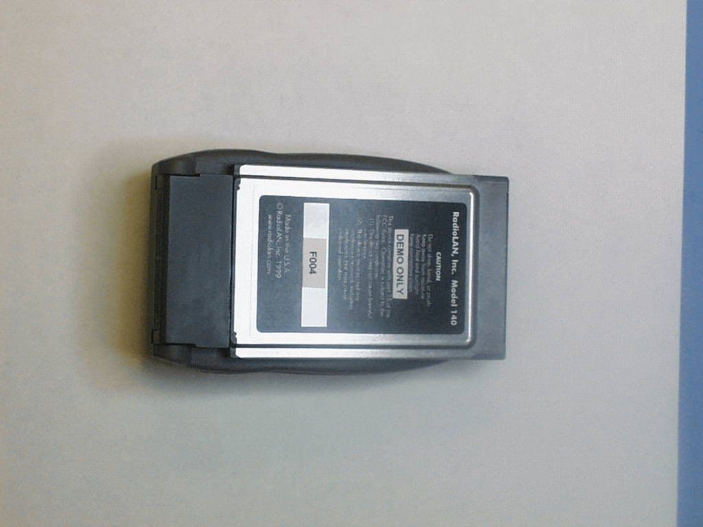
MCI140
Mar 16, 199910BaseT WLAN link
Equipment Class
DXX - Part 15 Low Power Communication Device TransmitterMCIPUNIIT
Mar 17, 1998UNII WLAN and Class A PCMCIA Card Maximum Output Power: 50 mW
Equipment Class
DXX - Part 15 Low Power Communication Device TransmitterMCIP101
Jul 31, 1997PCMCIA WLAN Card for Class A (Business) use.
Equipment Class
DXX - Part 15 Low Power Communication Device Transmitter