MCI-397Wireless Ethernet Switch
RadioLAN Marketing Group, Inc.
Click to zoom
Application Details
- Equipment Class
- DTS - Digital Transmission System
- Date of Grant
- Jul 24, 2003
- Application Purpose
- Original Equipment
- Date of Application
- Jul 24, 2003
- Equipment Note
- Wireless Ethernet Switch
- Frequency Range
- 5775.00000000 - 5775.00000000
- Country
- United States
Documents & Files
Document Text
Text extracted from the exhibit documents filed with the FCC. Open a document above to read the original.
Users Manual
© 2003 RadioLAN Marketing Group – All Rights Reserved Turn to page 3 for a Quick Start BridgeLINKBridgeLINK--Pro™ Wireless Ethernet BridgePro™ Wireless Ethernet Bridge Installation Guide BridgeLINK-Pro™ Installation Guide Page i © 2003 - RadioLAN Marketing Group, Inc. FCC Notice This equipment has been tested and found to comply with the limits for a Class B digital device, pursuant to Part 15 of the FCC rules. These limits are designed to provide reasonable protection against harmful interference in a residential installation. This equipment generates, uses, and can radiate radio frequency energy and, if not installed and used in accordance with the instructions, may cause harmful interference to radio communications. However, there is no guarantee that interference will not occur in a particular installation. If this equipment does cause harmful interference to radio or television reception, which can be determined by turning the equipment off and on, the user is encouraged to try to correct the interference by one of the following measures: • Reorient or relocate the receiving antenna. • Increase the separation between the equipment and receiver. • Connect the equipment into an outlet on a circuit different from that to which the receiver is connected. • Consult the dealer or an experienced radio/TV technician for help. FCC ID: MCI-397 FCC Rule Part(s): 15 Frequency Range: 5.725-5.875 GHz Equipment Class: Low Power Communication Device Transmitter Max. Output Power: 50 mW (+17 dB) This device has shown compliance with new rules adopted under Docket 87-389 and is not affected by Section 15.37, transition rule. Each radio is marked with its operating frequency. All interface cables must be shielded. BridgeLINK-Pro™ Installation Guide Page ii © 2003 - RadioLAN Marketing Group, Inc. This device complies with Part 15 of FCC rules. Operation is subject to the following two conditions: 1) this device may not cause harmful interference, and 2) this device must accept any interference received, including interference that may cause undesired operation. FCC regulations require that a person knowledgeable in electronics and trained in the correct installation of this device professionally install this device. Antennas used with this product shall be mounted in such a way so that there is at least 2m separation between all persons and the antenna, and at least 20 cm away from any other transmitting antenna. Professional installers have a responsibility to comply with FCC part 15 rules on antenna limits and amplification, and with RF exposure requirements in FCC rule section 1.1307 Unauthorized modifications to the device could void the End-user’s authority to operate it. Conventions The following conventions are used in this manual to highlight important topics: Bold Italic Indented Block Text – Highlights an important notice Bold – a field name Underline Italic – The name of a referenced document Blue Underline – A Hyperlink to a URL or E-Mail address Notice Symbol – Please take special notice BridgeLINK-Pro™ Installation Guide Page iii © 2003 - RadioLAN Marketing Group, Inc. Disclaimer The instructions in this document have been carefully checked for accuracy and are presumed to be reliable. RadioLAN Marketing Group and its writers assume no responsibility for inaccuracies and reserve the right to modify and revise this document without notice. It is RadioLAN Marketing Group’s goal to supply accurate and reliable documentation. If you discover an error in this document, please e-mail your comments or suggested corrections to [email protected]. No part of this publication may be placed in a retrieval system, transmitted, or reproduced in any way, including, but not limited to, photograph, photocopy, computer disk or other record, without prior written agreement from: RadioLANRadioLAN 185 Lewis Road, Suite 3185 Lewis Road, Suite 300 San Jose, CA 95111San Jose, CA 95111 Manual Revision 5 – P/N 890-029 BridgeLINK-Pro™ Installation Guide Page iv © 2003 - RadioLAN Marketing Group, Inc. Table of ContentsTable of Contents INTRODUCTION..................................................................................................................................................................................................1 THE BRIDGELINK-PRO™ SYSTEM...................................................................................................................................................................1 A TYPICAL BRIDGELINK-PRO™ APPLICATION.............................................................................................................................................2 QUICK SETUP GUIDE.......................................................................................................................................................................................3 INSTALLATION GUIDE....................................................................................................................................................................................5 UNPACKING THE BRIDGELINK-PRO UNITS......................................................................................................................................................5 BridgeLINK-Pro™ Processor Unit (BPU).................................................................................................................................................5 AC Power Adapter..........................................................................................................................................................................................8 PoE Adapter.....................................................................................................................................................................................................8 PLANNING THE INSTALLATION................................................................................................................................…
Text truncated - open the document above for the full version.
Cover Letter(s)
tel: 650-726-1263 fax: 650-726-1252 [email protected] Thomas N. Cokenias EMC &Radio Approvals Test & Consulting Services for Commercial, Military, International Compliance P.O. Box 1086 El Granada, CA 94018 FCC Laboratory 23 June 2003 7435 Oakland Mills Road Columbia, MD 21046 Attention: Application Examiner Reviewing Engineer Applicant: RadioLAN Marketing Group FCC ID: MCI-397 To whom it may concern, Request is hereby submitted, on behalf of my client RadioLAN to withhold from public review certain portions of the application for equipment certification for the referenced FCC identifier. In particular, the following sections of the application and report are requested to be kept confidential: Block Diagrams Schematic Operational Description Rationale for request for confidentiality: RadioLAN has invested considerable time and materials in research and development to produce the referenced product. Disclosure of the confidential portions of this application to competitors would give them competitive advantage in developing similar products. If you have questions or need further information, please contact the undersigned. Sincerely, tel: 650-726-1263 fax: 650-726-1252 [email protected] THOMAS N. COKENIAS EMC Consultant/Agent for RadioLAN Marketing Group
Cover Letter(s)
From: Mike Kuo Sent: Tuesday, July 22, 2003 6:39 PM To: Tom Cokenias (E-mail) Subject: FW: RadioLAN Marketing Group, Inc., FCC ID:MCI-397, AN03T3038 -----Original Message----- From: CERTADM Sent: Tuesday, July 22, 2003 6:38 PM To: '[email protected]' Subject: RadioLAN Marketing Group, Inc., FCC ID:MCI-397, AN03T3038 Notice_content ------------- Question #1: Please provide output power plot which was measured with spectrum analyzer. For your information: FCC provides the following information in regards to output power measurement for DTS : Output Power Measurements For all output power measurements using power meters, please assure that the probe video bandwidth is greater than the signal bandwidth. Otherwise measurement errors can result. We have noticed many instances, especially for DTS devices, where the output power measurement probe appeared to have a smaller video bandwidth than the signal bandwidth. When output power probes with sufficient bandwidth are not available to measure a particular signal than the alternate techniques, discussed in Joe Dichoso’s "Unlicensed" TCB training material from May 2003, should be used. These techniques include spectrum analyzer channel power functions and power/bandwidth extrapolation. UNII devices have alternate procedures defined in Public Notice DA 02-2138. Remember for all power measurements please use the correct measurement detector peak or average corresponding to the appropriate limit. Best Regards M.Kuo The items indicated above must be submitted before processing can continue on the above referenced application. Failure to provide the requested information within 60 days of the original e-mail date may result in application dismissal and forfeiture of the filing fee. Also, please note that partial responses increase processing time and should not be submitted. Any questions about the content of this correspondence should be directed to the e-mail address listed below the name of the sender.
Cover Letter(s)
From: [email protected] Sent: Friday, July 25, 2003 3:09 PM To: [email protected] Subject: FCC ID MCI-397 RadioLAN peak power Mike Attached are spectrum analyzer plots and excel spread sheet. I summed up the power in every 1 MHz in the emission bandwidth of the EUT, which is almost 90 MHz (20 dB BW is between 80 and 90 MHz). The charts show dBm for ease of reading, but I changed to LIN when doing the measurement and summed up in microwatts. I then converted microwatts to milliwatts to dBm, added 10 dB attenuator and 1 dB cable loss. Measurement this way yielded 15.9 dBm With modulation turned OFF and CW output, I measured about 17.1 dBm. Since pulse position modulation (PPM) turns cw output ON and OFF in a specific time sequence, CW is an accurate way to determine peak power. The summation difference is only about 1.2 dB lower, so I am confident the actual power output is between 15.9 dBm and 17.1 dBm I believe this answers the questions you had on this application but please don't hesitate to contact me if you have further questions. best regards Tom
Cover Letter(s)
tel: 650-726-1263 fax: 650-726-1252 [email protected] Thomas N. Cokenias EMC &Radio Approvals Test & Consulting Services for Commercial, Military, International Compliance P.O. Box 1086 El Granada, CA 94018 CCS 23 June 2003 561F Monterey Road Morgan Hill, CA 95037 Attention: Mike Kuo Reviewing Engineer Applicant: RadioLAN Marketing Group Re: Modifications to FCC ID: MCI-397 Dear Mike, Metal tape will be placed around the seams of all production units, as shown in the photograph. This modification was required for passing radiated emissions testing. RadioLAN has been informed of this requirement and will comply. tel: 650-726-1263 fax: 650-726-1252 [email protected] If you have questions or need further information, please contact the undersigned Sincerely, THOMAS N. COKENIAS EMC Consultant/Agent for RadioLAN Marketing Group cc: Tom Mitchell, RadioLAN Marketing Group
External Photos
RadioLAN Marketing Group Product Photographs FCC ID: MCI-397
ID Label/Location Info
RadioLAN Marketing Group FCC ID label location FCC ID: MCI-397 FCC ID label location (bottom surface of EUT)
Internal Photos
RadioLAN Marketing Group Product Photographs FCC ID: MCI-397 RadioLAN Marketing Group Product Photographs FCC ID: MCI-397 RadioLAN Marketing Group Product Photographs FCC ID: MCI-397 RadioLAN Marketing Group Product Photographs FCC ID: MCI-397 RadioLAN Marketing Group Product Photographs FCC ID: MCI-397 RadioLAN Marketing Group Product Photographs FCC ID: MCI-397 RadioLAN Marketing Group Product Photographs FCC ID: MCI-397
RF Exposure Info
Sheet1 MPE Calculations Applicant: RadioLAN Marketing Group FCC ID: MCI-397 RF Hazard Distance Calculation mW/cm2 from Table1:1.00 Max RF PowerTX AntennaMPE P, dBmG, dBiSafe Distance, cm 18.09.06.3 18.023.533.5 Basis of Calculations: E^2/3770 = S, mW/cm2 E, V/m = (Pwatts*Ggain*30)^.5/d, meters d = ((Pwatts*G*30)/3770*S))^0.5Pwatts*Ggain = 10^(PdBm-30+GdBi)/10) NOTE: For fixed location transmitters, minimum separation distance is 2m, even if calculations indicate MPE distance is less Page 1
Test Report
RadioLAN page 1 of 11 FCC ID: MCI-397 1 EMISSIONS TEST REPORT FOR A LOW POWER TRANSMITTER I. GENERAL INFORMATION Requirement: Federal Communications Commissions Test Requirements: 15.205, 15.207, 15.209, 15.247 Applicant: RadioLAN Marketing Group 185 Lewis Road - Suite 30 San Jose, CA 95111 FCC ID: MCI-397 II. DESCRIPTION OF EQUIPMENT UNDER TEST (EUT) RadioLAN FCC ID: MCI-397 is a DTS transceiver in the 5,725 - 5,850 MHz band. Output power : 50 mW (17 dBm) nominal 63 mW (18dBm) maximum Center frequency: 5.775 GHz (single channel) 6 dB BW 26.6 MHz 20 dB BW: 43 MHz The product is a self-contained wireless ethernet bridge product used with a separate power inserter and AC-DC converter. Input to the bridge unit is ethernet and DC power over CAT5 cable. The EUT was tested with the following antennas: Antenna type Mfr Model ID Gain (dBi) Flat panel Gabriel DFPD-1-52 23.5 omni Maxrad MFB58009 9.0 Additional antennas available for this transceiver: Flat panel European Antennas DPD18 18 dBi III. TEST LOCATION All emissions tests were performed at: Compliance Certification Services 571F Monterey Road Morgan Hill, CA 95037 T.N. Cokenias 15 June 2003 EMC Consultant/Agent for RadioLAN Marketing Group RadioLAN page 2 of 11 FCC ID: MCI-397 2 TEST PROCEDURES Radiated Emissions Test Requirement: 15.109, 15.205, 15.209, 15.247 Measurement Equipment Used: Agilent 4441 Spectrum Analyzer HP 8566 Spectrum analyzer HP 8447D pre-amplifier Miteq NSP2600-44 Preamp, 1- 26 GHz HP 11975A Preamplifier, 2 - 8 GHz (used with HP11970 external mixers) Schaffner Chase Bilog antenna, 30 - 2000 MHz EMCO Double Ridge Waveguide Horn, 1 - 18 GHz Antenna Research Associates MWH 1826/B, 18 - 26.5 GHz HP 11970A Harmonic mixer, 26.5 - 40 GHz HP 11970Q Harmonic mixer, 33 - 50 GHz HP 11970V Harmonic mixer, 50 - 75 GHz HP 11970W Harmonic mixer, 75 - 110 GHz Low loss antenna cable (0.7 dB/ft @ 24 GHz) Test Set-Up external mixer spectrum analyzer leveling pre-amp -OR- HPF 1-26 GHz pre-amp .3 - 3.0 m horn antenna bilog ant. - OR - 3 meters RadioLAN page 3 of 11 FCC ID: MCI-397 3 4441 spectrum analyzer 8447D pre-amp Test Method 1-40 GHz With the transmitter operating, the EUT was rotated 360° and the search antenna was raised and lowered in both polarities, all in an attempt to maximize the levels of the received emission for each harmonic and spurious emission up to 40 GHz. Testing was performed for two different types of antennas. Antenna type Mfr Model ID Gain (dBi) Flat panel Gabriel DFPD-1-52 23.5 omni Maxrad MFB58009 9.0 Test Results, 1- 40 GHz Refer to test results in separate Excel spreadsheets for each antenna Test Method 30 – 1000 MHz 1. The EUT was placed on a wooden table resting on a turntable on the open air test site. The search antenna was placed 10m from the EUT. The EUT antenna was mounted vertically as per normal installation. The EUT was set to transmit continuously . 2. The turntable was slowly rotated to locate the direction of maximum emission at each frequency generated by the EUT. 3. Once maximum direction was determined, the search antenna was raised and lowered in both vertical and horizontal polarizations. The maximum readings so obtained are recorded Test Results, 30 - 1000 MHz PASSES EN55022 class B limits. Refer to separate attachment. RadioLAN page 4 of 11 FCC ID: MCI-397 4 Test Requirement: 15.107, 15.207 Measurement Equipment Used: Rohde & Schwarz EMI Receiver ESHS-20 Fischer Custom Communication LISN, FCC-LISN-50/250-25-2 Test Set-up LISN AC Power supply/data inserter Figure 2 FIM Test Procedure 1. The EUT was placed on a wooden table 40 cm from a vertical ground plane and approximately 80 cm above the horizontal ground plane on the floor. The EUT was set to transmit in normal mode. 2. Line conducted data was recorded for both NEUTRAL and HOT lines. Test Results Refer to separate attached graph. RadioLAN page 5 of 11 FCC ID: MCI-397 5 Minimum 6 dB Bandwidth Test Requirement: 15.247(a)2 Measurement Equipment Used: HP 8593EM Spectrum Analyzer 6’ length low loss coaxial cable Test Procedures The EUT was configured on a test bench. The EUT was set for continuous operation. While the transmitter broadcast a steady stream of digital data, the analyzer MAX HOLD function was used to capture the envelope of the transmission occupied bandwidth. Test Results: Refer to attached spectrum analyzer charts. Data taken with RES BW of 100 kHz shows minimum 6 dB BW of 26.7 MHz. Minimum requirement is 500 kHz. RadioLAN page 6 of 11 FCC ID: MCI-397 6 Minimum 6 dB Bandwidth RadioLAN page 7 of 11 FCC ID: MCI-397 7 RF Power Output Test Requirement: 15.247(b) Measurement Equipment Used: HP 8566 Spectrum Analyzer 2 ft low loss RF cable Test Procedures 1. The EUT was configured on a test bench. 2. The pulse position modulation of the EUT was disabled. Pulse position modulation is achieved by switching RF output ON and OFF in a pre-determined time sequence. When the modulation is turned off, the resulting CW signal is the peak power output of the transmitter. Test Results Maximum output power is 18 dBm. RadioLAN page 8 of 11 FCC ID: MCI-397 8 Spurious Emissions, Conducted Test Requirement: 15.247(c) Measurement Equipment Used: Agilent 4441 Spectrum Analyzer 2 ft length low loss A coaxial RF cable Test Procedure The EUT was configured on a test bench. The cable was connected between the EUT antenna port and the spectrum analyzer input port. Spectrum analyzer RES BW was set to 100 kHz. While the transmitter broadcast a steady stream of digital data, the analyzer MAX HOLD function was used to capture the envelope of the transmission. Test Results Refer to attached data sheets for conducted emissions 30 MHz - 40Hz. . Data shows out of band emissions are suppressed well below the -20 dBc minimum required by the Rules. RadioLAN page 9 of 11 FCC ID: MCI-397 9 15.247(c): Spurious Emissions, Conducted RadioLAN page 10 of 11 FCC ID: MCI-397 10 Power Spectral Density Test Requirement: 15.247(d) Measurement Equipment Used: Agilent 4441 Spectr…
Text truncated - open the document above for the full version.
Test Report
Radiated Emissions, 30 -1000 MHz Class B EN 5502203U1969 030512A1 05/13/0710:05 AM William Zhuang TN Cokenias RadioLAN, WLAP, 5.8GHz DTS EUT with Power Supply 05/13/07 Freq.ReadingAFClossPre-ampLevelLimitMarginPolAzHeightMark (MHz)(dBuV)(dB)(dB)(dB)(dBuV/m)EN_B(dB)(H/V)(Deg)(Meter)(P/Q/A) 639.9960.2019.774.1928.0956.0846.0010.083mV0.001.50P 639.9963.1019.774.1928.0958.9846.0012.983mH0.002.50P FCC Class A: 640.0054.6019.774.1928.0950.4846.404.0810mH0.003.00P 639.9847.1019.774.1928.0942.9846.40-3.4210mH0.001.00P EN Class B 10m: 639.9847.1019.774.1928.0942.9837.005.9810mH0.001.00P 640.0045.8019.774.1928.0941.6837.004.6810mH0.001.50P 640.0044.1019.774.1928.0939.9837.002.9810mH0.001.50P 640.0052.6019.774.1928.0948.4837.0011.483mH0.001.20P 640.0048.9019.774.1928.0944.7837.007.783mH0.001.20P ADD ALUMINUM TAPE TO CHASSIS, then re-test: 640.0040.8019.774.1928.0936.6837.00-0.3210mH0.001.00P 480.0037.7017.153.5627.6230.7937.00-6.2110mH0.001.00P 400.0039.6015.883.1127.2731.3237.00-5.6810mH0.001.00P 320.0035.3015.362.8526.6926.8237.00-10.1810mH0.001.00P 240.0043.1011.922.4626.5530.9337.00-6.0710mH0.003.00P 160.0034.9017.041.9826.7827.1430.00-2.8610mH0.002.50P Only noise floor for vertical Total data #: 15 V.2a
Test Report
06/23/03 High Frequency Measurement Compliance Certification Services, Morgan Hill Open Field Site Test Engr:William Zhuang Project #:03U1969-1 Company:T.N. Cokenias EUT Descrip.:RadioLAN, WLAP, 5.8GHz DTS EUT M/N:Aruba Test Target:FCC15.247 Mode Oper:EUT with Panel Antenna Test Equipment: Peak Measurements:Average Measurements: 1 MHz Resolution Bandwidth1 MHz Resolution Bandwidth 1MHz Video Bandwidth10Hz Video Bandwidth fDistRead PkRead Avg.AFCLAmpD CorrHPFPeakAvgPk LimAvg LimPk MarAvg MarNotes GHzfeetdBuVdBuVdB/mdBdBdB dBuV/mdBuV/mdBuV/mdBuV/mdBdB 11.5609.969.448.139.27.7-44.70.11.072.751.474.054.0-1.3-2.6V 11.5609.966.947.239.27.7-44.70.11.070.250.574.054.0-3.8-3.5H 23.1069.959.242.536.210.7-45.30.11.062.045.374.054.0-12.0-8.7V 23.1069.960.441.836.210.7-45.30.11.063.244.574.054.0-10.8-9.5H 1.0V 1.0V 1.0V 1.0V 1.0V 1.0V 1.0V 1.0V 1.0V 1.0V 1.0V 1.0H 1.0H 1.0H 1.0H 1.0H 1.0H 1.0H 1.0H 1.0H 1.0H 1.0H 1.0H 1.0H 1.0H fMeasurement FrequencyAmpPreamp GainAvg LimAverage Field Strength Limit DistDistance to AntennaD CorrDistance Correct to 3 metersPk LimPeak Field Strength Limit ReadAnalyzer ReadingAvgAverage Field Strength @ 3 mAvg MarMargin vs. Average Limit AFAntenna FactorPeakCalculated Peak Field StrengthPk MarMargin vs. Peak Limit CLCable LossHPFHigh Pass Filter T86 Miteq 924341 Pre-amplifer 1-26GHzEMCO Horn 1-18GHz T60; S/N: 2238 @1m Spectrum Analyzer Horn > 18GHz T87; ARA 18-26GHz; S/N:1049 (2 ft) gfedc (2 ~ 3 ft) gfedc (4 ~ 6 ft) gfedcb (12 ft) gfedcb Hi Frequency Cables
Test Report
561F Monterey Road, San Jose, CA 95037 USA Tel: (408) 463-0885 Fax: (408) 463-0888 Data#: 7File#: 03U1969.EMIDate: 05-12-2003 Time: 14:51:00 Level (dBuV)Compliance Certification Service 80 35 -10 0.1530 Frequency (MHz) 0.51.2.5.1020 AVERAGE CISPR CLASS-B Trace: 3 Ref Trace: Project # : 03U1969 Test Engineer : William Zhuang Company : T.N. Cokenias EUT : RadioLAN, WLAP, 5.8 GHz DTS Model : Aruba Configuration : EUT with power supply Target of Test: EN55022 Class B : L1: Peak ( Black ), L2: peak(Green) : 115Vac, 60Hz
Test Report
06/23/03 High Frequency Measurement Compliance Certification Services, Morgan Hill Open Field Site Test Engr:William Zhuang Project #:03U1969-1 Company:T.N. Cokenias EUT Descrip.:RadioLAN, WLAP, 5.8GHz DTS EUT M/N:Aruba Test Target:FCC15.247 Mode Oper:EUT with Omni Antenna Test Equipment: Peak Measurements:Average Measurements: 1 MHz Resolution Bandwidth1 MHz Resolution Bandwidth 1MHz Video Bandwidth10Hz Video Bandwidth fDistRead PkRead Avg.AFCLAmpD CorrHPFPeakAvgPk LimAvg LimPk MarAvg MarNotes GHzfeetdBuVdBuVdB/mdBdBdB dBuV/mdBuV/mdBuV/mdBuV/mdBdB 11.5629.963.344.639.27.7-44.70.11.066.648.074.054.0-7.4-6.0V 11.5629.962.645.139.27.7-44.70.11.065.948.474.054.0-8.1-5.6H 23.1099.962.747.436.210.7-45.30.11.065.450.274.054.0-8.6-3.8V 23.1099.959.046.036.210.7-45.30.11.061.748.774.054.0-12.3-5.3H 1.0V 1.0V 1.0V 1.0V 1.0V 1.0V 1.0V 1.0V 1.0V 1.0V 1.0V 1.0H 1.0H 1.0H 1.0H 1.0H 1.0H 1.0H 1.0H 1.0H 1.0H 1.0H 1.0H 1.0H 1.0H fMeasurement FrequencyAmpPreamp GainAvg LimAverage Field Strength Limit DistDistance to AntennaD CorrDistance Correct to 3 metersPk LimPeak Field Strength Limit ReadAnalyzer ReadingAvgAverage Field Strength @ 3 mAvg MarMargin vs. Average Limit AFAntenna FactorPeakCalculated Peak Field StrengthPk MarMargin vs. Peak Limit CLCable LossHPFHigh Pass Filter T86 Miteq 924341 Pre-amplifer 1-26GHzEMCO Horn 1-18GHz T60; S/N: 2238 @1m Spectrum Analyzer Horn > 18GHz T87; ARA 18-26GHz; S/N:1049 (2 ft) gfedc (2 ~ 3 ft) gfedc (4 ~ 6 ft) gfedcb (12 ft) gfedcb Hi Frequency Cables
Test Report
Antenna Conducted Output RadioLAN Marketing Group FCC ID: MCI-397 PPM modulation ON -20 dB BW = 80 MHz Power was summed across band in LINEAR mode for every 1 MHz Power sum = 15.86 dBm . Refer to separate Excel spread sheet. FCC ID: MCI-397 PPM modulation ON -20 dB BW = 80 MHz CW output = 6.13 dBm + 10 dB attn + 1 dB CL = 17.13 dBm peak output
Test Report
F, mhzReading, uW Lin uW 573552.14.4 573630.42.8 573725.362.8 573819.12.8 573913.82 574027.92.6 574135.43.3 574287.18.9 574350.34.9 574430.53.3 574512.81.5 57464.80.486 57477.90.167 574827.42.9 574951.35.6 57503.60.396 5751111.2 575240.34.1 5753157.915.5 5754249.325.6 5755590.272.7 5756461.344.3 5757338.434.6 5758284.234.6 5759249.323.2 5760494.942.7 5761530.652.5 57621420141.4 5763576.254.7 5764632.860.5 5765354.643 5766433.444 5767631.364.3 5768969.8100.8 57691870189.5 57701000125.1 5771713.267.1 5772295.13.9 5773198.117.2 5774118017.8 57752720306.3 57761790160 577776.910 5778180.420.4 5779393.444.5 5780743.989.6 57811290122.2 57821780184.3 5783750.170.4 5784477.244 5785454.945.9 5786357.648.6 5787510.752.3 5788524.757.2 57891170111.94 5790470.647.28 5791484.543.15 5792164.215.4 5793221.223.3 5794326.131.3 579562254.4 5796384.640.6 5797229.524.2 5798128.613.3 579941.43.8 580014.81.4 580136.43.3 5802127.612.3 580322.13.5 58044.90.483 58058.70.733 580620.22.1 5807373.7 580857.58.3 580980.88.1 581029.23.5 581130893.362.4 58122 58132 58142.75 58154 58161.9 58171.7 58181.1 58190.626 58200.583 58210.624 58221.1 58230.601 58240.288 58250.104 5826 5827 5828 5829 5830 5831 5832 5833 5834 5835 5836 5837 5838 5839 5840 5841 5842 5843 5844 5845 5846 5847 5848 5849 5850 5851 5852 5853 5854 5855 5856 5857 5858 5859 5860 5861 5862 5863 5864 5865 5866 5867 5868 5869 5870 5871 5872 5873 5874 5875 5876 5877 5878 5879 5880 5881 5882 5883 5884 5885 5886 5887 5888 5889 5890 5891 5892 5893 5894 5895 5896 5897 5898 5899 5900 5901 5902 5903 5904 5905 5906 5907 5908 5909 5910 5911 5912 5913 5914 5915 5916 5917 5918 5919 5920 5921 5922 5923 5924 5925 5926 5927 5928 5929 5930 5931 5932 5933 5934 5935 5936 5937 5938 5939 5940 5941 5942 5943 5944 5945 5946 5947 5948 5949 5950 5951
Test Setup Photos
RadioLAN Marketing Group Test Set-up Photographs FCC ID: MCI-397 RadioLAN Marketing Group Test Set-up Photographs FCC ID: MCI-397 RadioLAN Marketing Group Test Set-up Photographs FCC ID: MCI-397 RadioLAN Marketing Group Test Set-up Photographs FCC ID: MCI-397
Contact Information
Applicant
Tom Mitchell(President and CEO)
408-365-6200Fax: 408-365-7675
Test Firm
Compliance Certification Services IncSteve Cheng
Technical Specifications
| # | Rule Parts | Frequency Range | Power Output |
|---|---|---|---|
| 1 | 15C | 5.78 GHz - 5.78 GHz | 39.00 mW |
Other Applications from RadioLAN Marketing Group, Inc.

MCI-387
Nov 24, 20025.7GHz Wireless LAN
Equipment Class
DTS - Digital Transmission System
MCI-377
Nov 24, 20025.7GHz Wireless LAN
Equipment Class
DTS - Digital Transmission System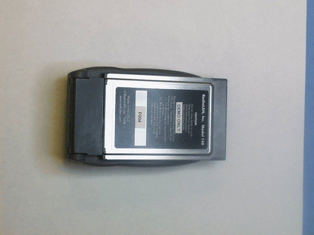
MCI140
Mar 16, 199910BaseT WLAN link
Equipment Class
DXX - Part 15 Low Power Communication Device TransmitterMCIPUNIIT
Mar 17, 1998UNII WLAN and Class A PCMCIA Card Maximum Output Power: 50 mW
Equipment Class
DXX - Part 15 Low Power Communication Device TransmitterMCIP101
Jul 31, 1997PCMCIA WLAN Card for Class A (Business) use.
Equipment Class
DXX - Part 15 Low Power Communication Device Transmitter