MFFRWP3841Radio-wave Touch Probe
m&h Inprocess messtechnik GmbH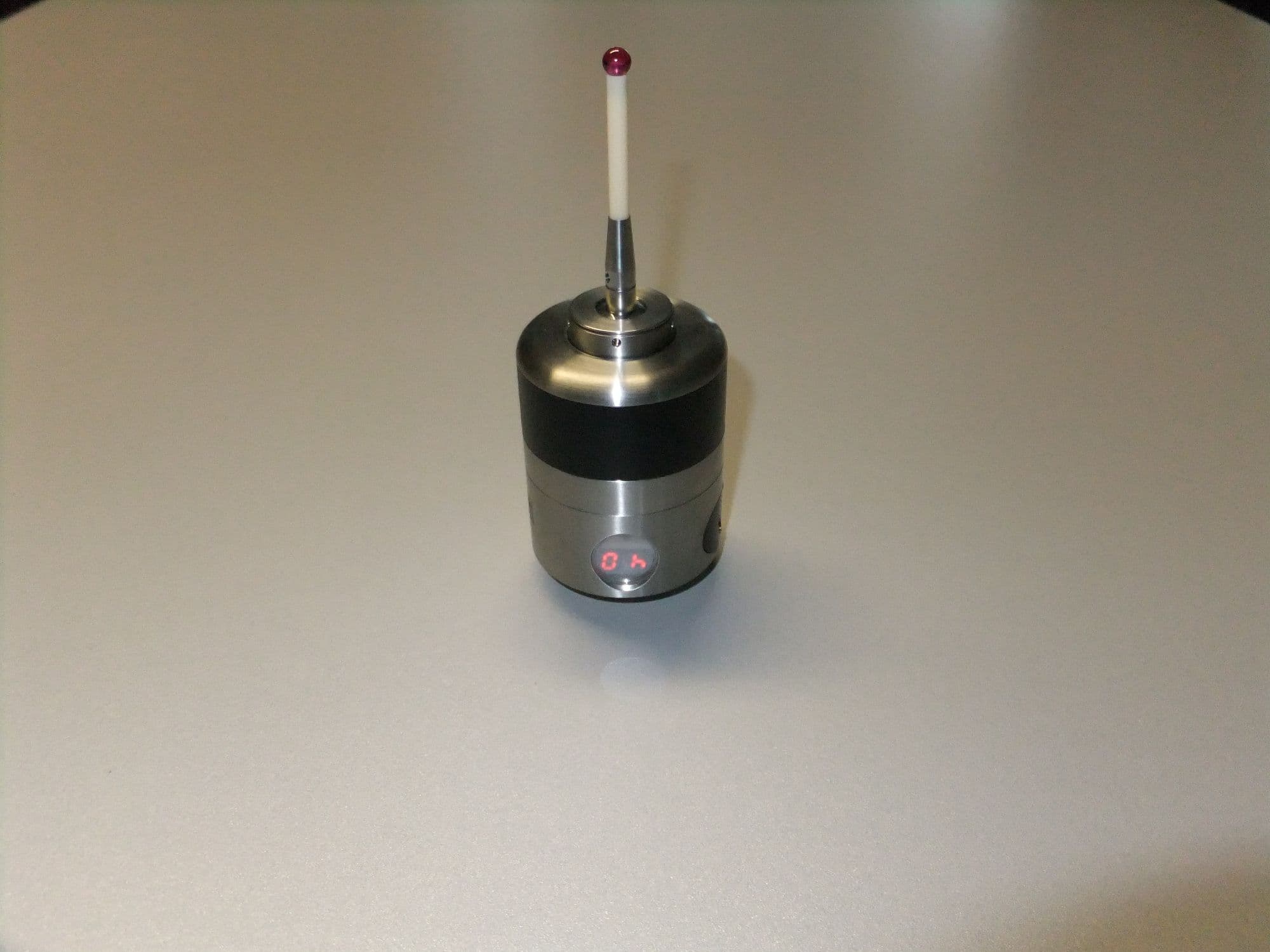
Click to zoom
Application Details
- Equipment Class
- DXX - Part 15 Low Power Communication Device Transmitter
- Date of Grant
- Jan 16, 2012
- Application Purpose
- Original Equipment
- Date of Application
- Jan 16, 2012
- Equipment Note
- Radio-wave Touch Probe
- Frequency Range
- 433.07500000 - 434.65000000
- Country
- Germany
Documents & Files
Document Text
Text extracted from the exhibit documents filed with the FCC. Open a document above to read the original.
Users Manual
m&h Inprocess Messtechnik GmbH x Am Langholz 11 x D-88289 Waldburg Fon +49(0)7529 / 9733-0 x Fax +49 (0)7529 / 9733-7 x [email protected] Radio-wave Touch Probe RWP38.41 www.mh-inprocess.com OPERATING INSTRUCTIONS (Translation of the original operating instructions) Page System Components, Technical Data, Dimensions 1 Stylus Change, Battery Replacement 2 Aligning Stylus to Spindle Centre 3 Channels and Frequencies, Setting the Channel 4 Activation Code and Time-out Adjustment 5 Optical Status Display, Adjusting Trigger Force, Maintenance 6 Probe ON/OFF Procedure, Mounting the Shank 7 HSK Shanks, SK Shanks 8 Coromant Capto Shanks, THERMO-LOCK ® Shanks, Other Shanks 9 Measuring Unit Extension 10 Styli, Accessories 11 Safety Advice, Declaration of Conformity, FCC/RSS-Declaration 12 Delivery Contents, Spare Parts, Accessories 13 BA-RWP3841-2311-WEST Subject to change without notice Radio-wave Touch Probe RWP38.41 Radio-wave Receiver RWR95.40 Radio-wave Touch Probe RWP38.41 1 System Components Technical Data Dimensions Sensing Directions: ± X; ± Y; -Z Max.Stylus Overtravel: XY ±12.5°; Z –6mm (0.24”) Trigger Force XY = 0.3-1.4N; Z = 2.5-12.5N with 50mm Stylus: adjustable Factory Settings: XY = 0.96N; Z = 8.5N Recommended Probing Speed: 254mm/min – 2000mm/min Power Supply: 2x Battery 3,6V Type ½ AA (1200mAh) Battery lifetime: 100% = 325h 5% = 219d Standby = 230d Material: Stainless steel Weight without Shank: approx. 460g Temperature Range: Operating: 10° - 50°C Storage: 5° - 70°C Unidirectional max. 2sigma ±1μm with Repeatability: 50mm stylus at 254mm/min Guaranteed Life-time of Measuring Unit: 10 million deflections Frequency Range: 433.075 – 434.650 MHz Number of Channels: 64 Channel Spacing: 25 KHz Sealing: IP68: EN60529 M4 Stylus Channel display Channel adjustment Stylus runout adjustment Customer-specified shank Battery compartment Radio-wave Touch Probe RWP38.41 2 M=2Nm (1,47 lbf.ft) Stylus Change Attention ! After changing the stylus: Adjust stylus to spindle centre! Calibrate probe ! Battery Replacement Attention ! Before opening probe, clean and dry well. Do NOT blow off with compressed air! Open battery cover by a circular motion. Remove empty batteries. Make sure positive and negative ends of battery are inserted correctly. When closing the battery cover, ensure the O-ring for sealing will be properly inserted. Replace empty batteries immediately. Mounting pin #0885 Battery cover 38.41-BD (incl. O-Ring 21x2 Viton #4475) 2x Battery 3,6V Type ½ AA #4316 Battery cover o pen Battery cover closed Radio-wave Touch Probe RWP38.41 3 Aligning Stylus to Spindle Centre 1 Set „C“ Screws - Loosen all "A" screws 2 turns - Loosen the "C" screws - Using the long end of the Hex key tighten both "C" screws lightly 3 Tighten „C“ Screws - Tighten both “C” screws using the short end of the Hex Key 5 Retighten „C“ Screws - Using the short end of the Hex Key - Securely retighten both "C" screws 2 Adjustment to <20μ - Set dial gauge in front of the stylus like on the picture - Turn the probe until the maximum deviation is shown on the indicator - Turn the "A" screws half of the indicator reading - Loosen the "A" screws that were used 1 turn - Repeat procedure until runout is < 20μ 4 Adjustment to <5μ - Turn the probe until the maximum deviation is shown on the indicator - Turn the "A" screws half of the indicator reading - Loosen the "A" screws that were used 1 turn - Repeat procedure until runout is < 5μ 6 Set „A“ Screws against each other - Set opposing „A“ screws (0° - 180°) against each other - Repeat with the other two opposing „A“ screws (90 - 270°) If the runout goes out of adjustment: - Turn the probe until the maximum deviation is shown on the indicator - Carefully loosen the „A“ screws on the opposite side until the runout is < 5μ - Set the opposing „A” screws against the newly adjusted one Hexagon key AF2.5mm #1346 Hexagon key AF2mm #1097 Radio-wave Touch Probe RWP38.41 4 Channel Frequency (MHz) Channel Frequency (MHz) Channel Frequency (MHz) Channel Frequency (MHz) 00 locked 18 433,300 36 433,875 54 434,375 01 433,925 19 433,325 37 433,900 55 434,400 02 434,075 20 433,350 38 433,950 56 434,425 03 433,075 21 433,400 39 433,975 57 434,450 04 locked 22 433,425 40 434,000 58 434,475 05 433,175 23 433,450 41 434,025 59 434,500 06 433,275 24 433,500 42 434,050 60 434,525 07 433,375 25 433,525 43 434,100 61 434,550 08 433,475 26 433,550 44 434,125 62 434,575 09 433,575 27 433,600 45 434,150 63 434,600 10 433,675 28 433,625 46 434,175 64 434,625 11 433,775 29 433,650 47 434,200 65 434,650 12 433,100 30 433,700 48 434,225 13 433,125 31 433,725 49 434,250 66-99 locked 14 433,150 32 433,750 50 434,275 15 433,200 33 433,800 51 434,300 16 433,225 34 433,825 52 434,325 17 433,250 35 433,850 53 434,350 Channels and Frequencies Setting the Channel Procedure: Ensure the probe is off Press the button until the channel is displayed Press the button again until the desired channel is displayed Channel display shuts off after 5 sec. Channel is now adjusted! Button Radio-wave Touch Probe RWP38.41 5 „A“ „B „C“ Activation Code and Time-Out Adjustment With 3 available activation codes, „A“ / „B“ / „C“, it is possible to operate up to 3 systems with one receiver. The receiver sends the selected activation code and expect only signals from the selected activation code. Every activation code is available with the respective time-out adjustment „Radio-wave OFF” and „3min”. When using the setting „Radio-wave OFF”, the measuring system must be deactivated by the receiver with an M-Code! When using the setting „3min”, the measuring system must also be deactivated with an M-Code, but in case of a failure during deactivation the probe will be automatically deactivated after 3min! The „1“ in front of the activation code shows that the time-out is activated, the „0“ that it is deactivated! In the display: = 0.A. → Time-out is deactivated („Radio-wave OFF“) / Activation code „A“ = 1.C. → Time-out …
Text truncated - open the document above for the full version.
Users Manual
Radio-wave Touch Probe RWP38.41 12 NOTICE: This device complies with Part 15 of the FCC Rules and with RSS-210 of Industry Canada. Operation is subject to the following two conditions: 1. this device may not cause harmful interference, and 2. this device must accept any interference received, including interference that may cause undesired operation. Le présent appareil est conforme aux CNR d'Industrie Canada applicables aux appareils radio exempts de licence. L'exploitation est autorisée aux deux conditions suivantes: (1) l'appareil ne doit pas produire de brouillage, et (2) l'utilisateur de l'appareil doit accepter tout brouillage radioélectrique subi, même si le brouillage est susceptible d'en compromettre le fonctionnement. NOTICE: Changes or modifications made to this equipment not expressly approved by m&h Inprocess Messtechnik GmbH may void the FCC authorization to operate this equipment. NOTE: This equipment has been tested and found to comply with the limits for a Class B digital device, pursuant to Part 15 of the FCC Rules. These limits are designed to provide reasonable protection against harmful interference in a residential installation. This equipment generates, uses and can radiate radio frequency energy and, if not installed and used in accordance with the instructions, may cause harmful interference to radio communications. However, there is no guarantee that interference will not occur in a particular installation. If this equipment does cause harmful interference to radio or television reception, which can be determined by turning the equipment off and on, the user is encouraged to try to correct the interference by one or more of the following measures: • Reorient or relocate the receiving antenna. • Increase the separation between the equipment and receiver. • Connect the equipment into an outlet on a circuit different from that to which the receiver is connected. • Consult the dealer or an experienced radio/TV technician for help. M&h Messtechnik GmbH Model: RWP38.41 FCC ID: MFFRWP3841 IC: 5782A-RWP3841 Sicherheitshinweise – Bitte beachten ! 1. Das manuelle oder automatische Positionieren eines Messtasters sollte dahingehend geschützt sein, dass ein unvorhergesehenes Auslenken des Taststiftes außerhalb des Antastvorganges zu einem sofortigen Vorschub-Stop führt ! 2. Ein Vorschub- oder Spindel-Stop, ausgelöst durch ein Schaltsignal oder Betriebsbereit-Signal eines Messtasters, darf nur dann erfolgen, wenn ein Messtaster in der Spindel ist. Diese Sicherheitsabfrage verhindert, dass die Spindel oder der Vorschub während einer normalen Fräsbearbeitung gestoppt wird, falls aus einem der nachfolgenden Gründe ein Signal vom Messtaster ausgelöst werden sollte: • Kunde wechselt Batterien und prüft anschließend die Funktionen des Messtasters, • Eine weitere Maschine mit einem Funk-Messtaster wird in Betrieb genommen und dieser Messtaster sendet auf dem gleichen Kanal wie ein zuvor installierter Taster. Konformitätserklärung Die EG-Konformitätserklärung wird auf Anfrage beim Hersteller in digitaler Form zur Verfügung gestellt. FCC / RSS - Declaration
Cover Letter(s)
CONFIDENTIALITY REQUEST for Certification Service in USA Federal Communication Commission Equipment Authorization Division, Application Processing Branch 7435 Oakland Mills Road Columbia, MD 21048 June 28, 2011 TO WHOM IT MAY CONCERN Pursuant to Paragraphs §0.457 and 0.459 of the Commission’s Rules (47 C.F.R.) and Section §552(b)(4) of the Freedom of Information Act, we requests confidentiality for the following products: FCC ID Model name MFFRWP3841 RWP38.41 For the product stated above, we request permanent confidentiality for exhibits which contain Operational Description, Block Diagram, Schematics, Parts Lists or Tune Up Information. The above exhibits contain our trade secrets and proprietary information that could be of benefit to our competitors. If you have any questions, please feel free to contact me at the address shown below. Sincerely, Name: Christoph Wiest Company: m&h Inprocess Messtechnik GmbH Address: Am Langholz 11, 88289 Waldburg Phone: +49-7529-9733-38 Fax: +49-7529-9733-59 Email: [email protected]
Test Report
2012-01-18 Page 1 of 29 TEST REPORT Test report no.: 1-3449/11-01-02-B Testing laboratory Applicant CETECOM ICT Services GmbH Untertuerkheimer Strasse 6 – 10 66117 Saarbruecken / Germany Phone: + 49 681 5 98 - 0 Fax: + 49 681 5 98 - 9075 Internet: http://www.cetecom.com e-mail: [email protected] Accredited Testing Laboratory: The testing laboratory (area of testing) is accredited according to DIN EN ISO/IEC 17025 (2005) by the Deutsche Akkreditierungsstelle GmbH (DAkkS) The accreditation is valid for the scope of testing procedures as stated in the accreditation certificate with the registration number: D-PL-12076-01-01 Area of Testing: Radio/Satellite Communications m&h Inprocess Messtechnik GmbH Am Langholz 11 88289 Waldburg / GERMANY Phone: +49 752 997-3338 Fax: +49 752 997-3339 Contact: Christoph Wiest e-mail: [email protected] Phone: +49 752 997-3338 Manufacturer m&h Inprocess Messtechnik GmbH Am Langholz 11 88289 Waldburg / GERMANY Test standard/s 47 CFR Part 15 Title 47 of the Code of Federal Regulations; Chapter I Part 15 - Radio frequency devices RSS – GEN Issue 3 General Requirements and Information for the Certification of Radio Apparatus For further applied test standards please refer to section 3 of this test report. Test Item Kind of test item: Touch Trigger Probe Model name: RWP38.41 FCC ID: MFFRWP3841 IC: 5782A-RWP3841 Frequency [MHz]: 433.075 MHz – 434.65 MHz Technology tested: Proprietary Antenna: Integrated antenna Power Supply: 7.20 V DC by Battery (LI-110 / ER 14250) Temperature Range: +22°C This test report is electronically signed and valid without handwriting signature. For verification of the electronic signatures, the public keys can be requested at the testing laboratory. Test report authorised: Test performed: Stefan Bös Jakob Reschke Senior Testing Manager Testing Manager Test report no.: 1-3449/11-01-02-B 2012-01-18 Page 2 of 29 1 Table of contents 1 Table of contents ............................................................................................................................................ 2 2 General information ....................................................................................................................................... 3 2.1 Notes and disclaimer .......................................................................................................................... 3 2.2 Application details ............................................................................................................................... 3 3 Test standard/s ............................................................................................................................................... 3 4 Test environment ............................................................................................................................................ 4 5 Test item .......................................................................................................................................................... 4 6 Test laboratories sub-contracted ................................................................................................................. 4 7 Summary of measurement results ............................................................................................................... 5 8 RF measurements .......................................................................................................................................... 6 8.1 Description of test setup .................................................................................................................... 6 8.1.1 Radiated measurements............................................................................................................. 6 8.1.2 Conducted measurements.......................................................................................................... 7 8.2 Additional comments .......................................................................................................................... 7 8.3 RSP100 test report cover sheet / performance test data ................................................................ 8 9 Measurement results ...................................................................................................................................... 9 9.1 Timing of the transmitter .................................................................................................................... 9 9.2 Bandwidth of the modulated carrier ................................................................................................ 11 9.3 Field strength of the fundamental ................................................................................................... 13 9.4 Fieldstrength of the harmonics and spurious ................................................................................ 14 10 Test equipment and ancillaries used for tests ................................................................................... 18 11 Observations ......................................................................................................................................... 19 Annex A Photographs of the test setup ...................................................................................................... 20 Annex B External photographs of the EUT ................................................................................................. 21 Annex C Internal photographs of the EUT .................................................................................................. 26 Annex D Document history .......................................................................................................................... 28 Annex E Further information ........................................................................................................................ 28 Annex F Accreditation Certificate ........................…
Text truncated - open the document above for the full version.
Test Setup Photos
Test report no.: 1-3449/11-01-02-A 2011-12-14 Page 20 of 29 Annex A Photographs of the test setup Photo documentation Photo 1:
Contact Information
Applicant
Christoph Wiest
Test Firm
cetecom advanced GmbHGerald Schmidt
Technical Specifications
| # | Rule Parts | Frequency Range | Power Output |
|---|---|---|---|
| 1 | 15C | 433.075 MHz - 434.65 MHz | - |
Other Applications from m&h Inprocess messtechnik GmbH

MFFLSR100
Jul 31, 2026Laser Scanner
Equipment Class
DTS - Digital Transmission System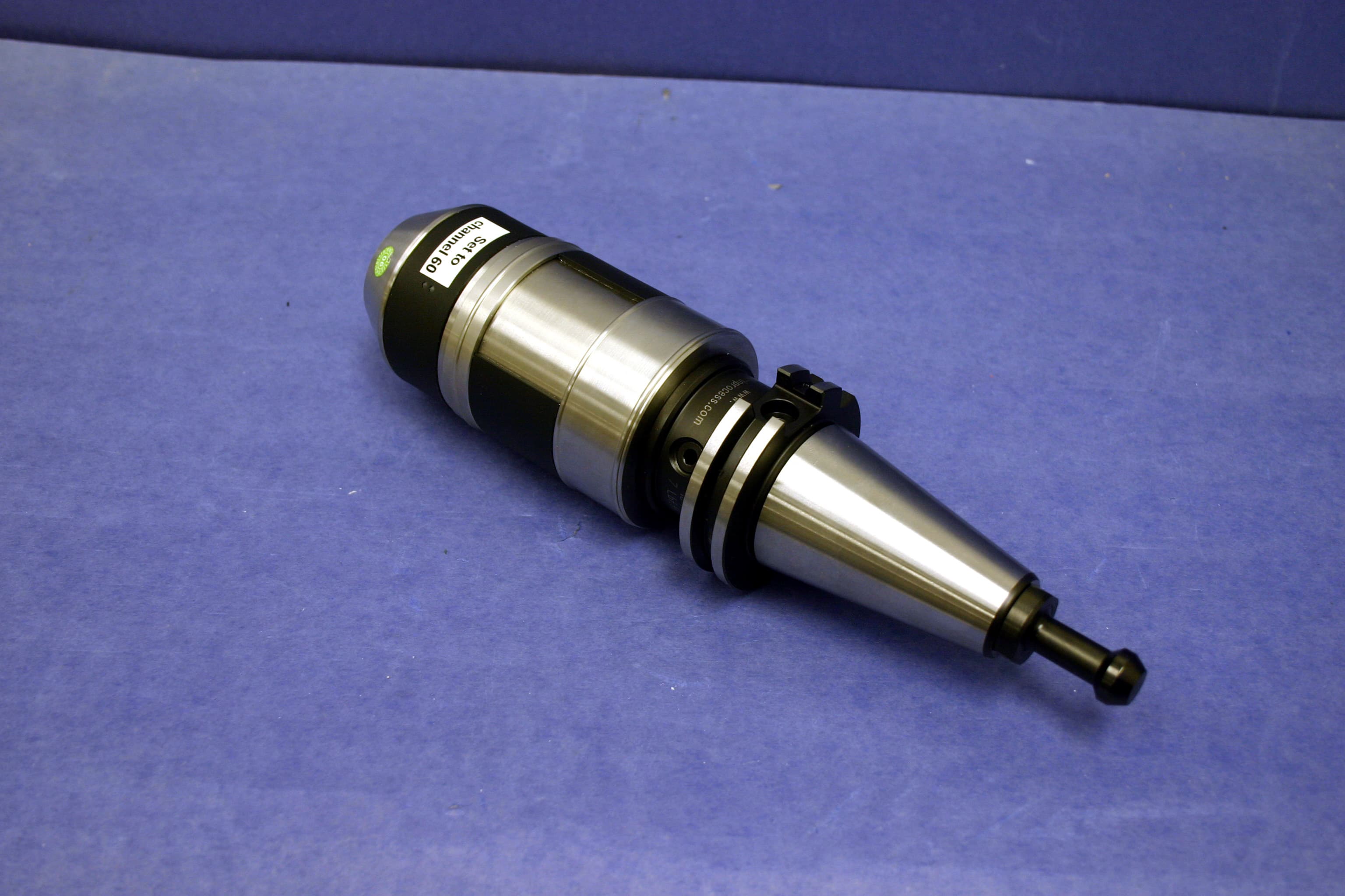
MFFRWP20
Mar 28, 2010RADIO WAVE PROBE 20xx
Equipment Class
DXX - Part 15 Low Power Communication Device Transmitter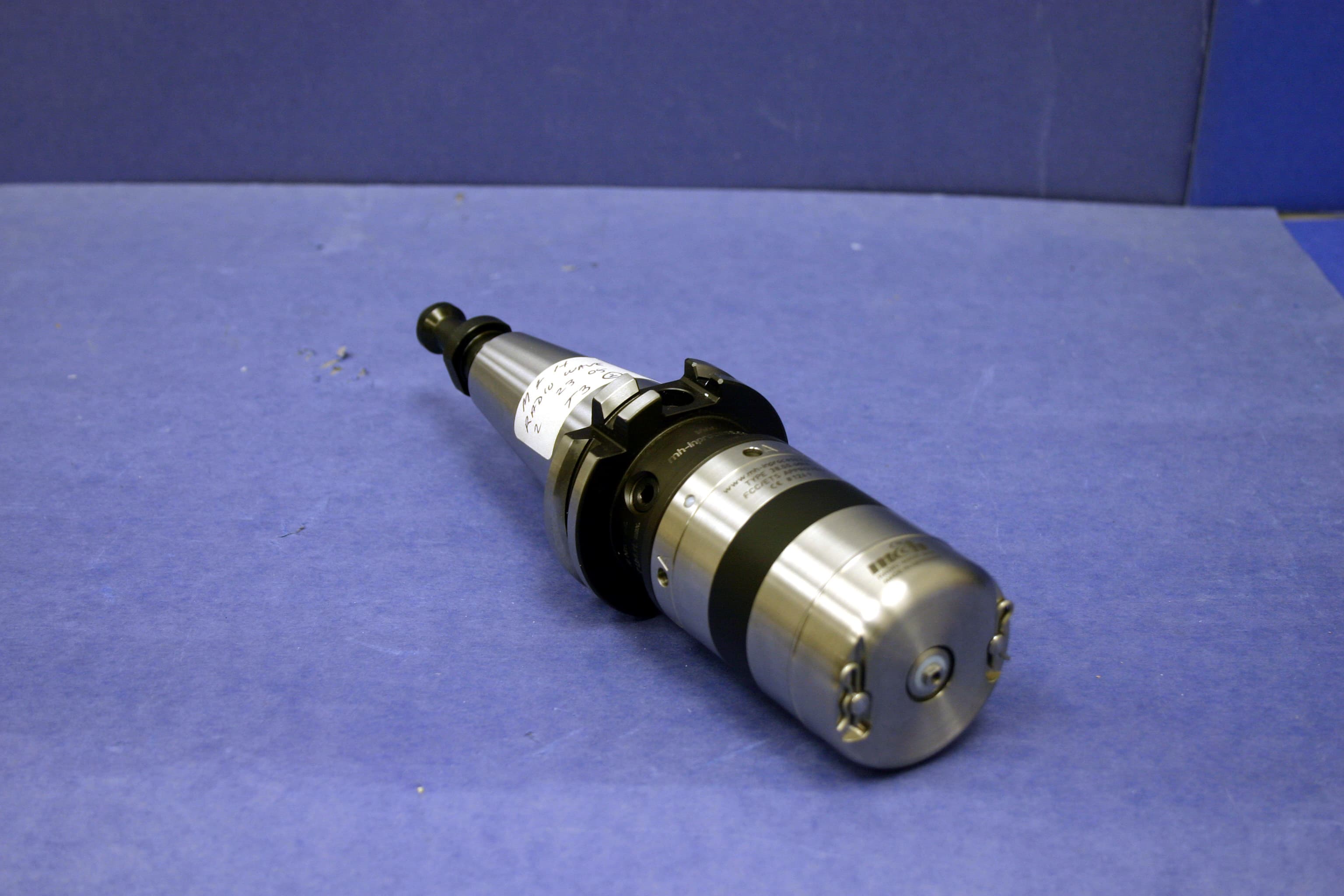
MFFRWP38
Feb 25, 2010RADIO WAVE PROBE 38XX
Equipment Class
DXX - Part 15 Low Power Communication Device TransmitterMFFRW1433
Oct 18, 1995RF Probe Receiver
Equipment Class
CYY - Communications Receiver used w/Pt 15 TransmitterMFFRWP433
Oct 18, 1995RF Probe
Equipment Class
DXX - Part 15 Low Power Communication Device Transmitter