MFMSAMP24SWireless LAN System with Amplifier
Teletronics International Inc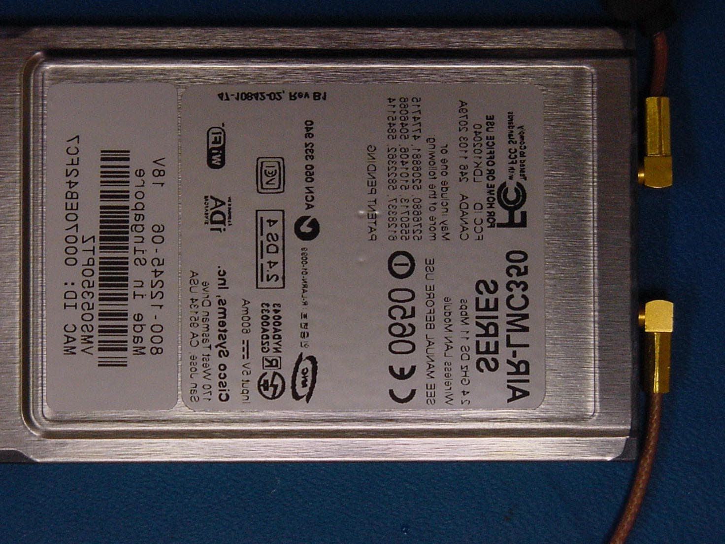
Click to zoom
Application Details
- Equipment Class
- DTS - Digital Transmission System
- Date of Grant
- Oct 20, 2002
- Application Purpose
- Original Equipment
- Date of Application
- Oct 17, 2002
- Equipment Note
- Wireless LAN System with Amplifier
- Frequency Range
- 2422.00000000 - 2452.00000000
- Country
- United States
Documents & Files
Document Text
Text extracted from the exhibit documents filed with the FCC. Open a document above to read the original.
Users Manual
Extended Range Amplified WLAN System Guide Version 07/18/02 Teletronics International Extended Range Amplified Wireless LAN System (For Cisco Aironet 350 Series Wireless Product) System Description, Configuration and Installation Guide Teletronics International Inc. 1803 Research Blvd. Suite 404 Rockville, MD 20850 Extended Range Amplified WLAN System Guide Version 07/18/02 TABLE OF CONTENTS 1 INTRODUCTION ............................................................................................................................................5 1.1 A BOUT THIS G UIDE ...........................................................................................................................................5 1.2 W HO S HOULD U SE THIS G UIDE .........................................................................................................................5 1.3 N OTES AND W ARNINGS TO THE U SER AND I NSTALLER .....................................................................................5 1.3.1 Interference and Equipment Limits ..........................................................................................................5 1.3.2 Cautions and Warnings ............................................................................................................................6 2 SYSTEM DESCRIPTION................................................................................................................................9 2.1 E XTENDED R ANGE WLAN S YSTEM I NFRASTRUCTURE .....................................................................................9 2.2 G ENERAL D ESCRIPTION .....................................................................................................................................9 2.3 S YSTEM F EATURES ..........................................................................................................................................10 2.4 P LATFORM M ODELS ........................................................................................................................................10 2.4.1 Wireless LAN External Amplifier .........................................................................................................11 2.4.2 Additional Wireless LAN System Components .....................................................................................13 3 CONFIGURING THE EXTENDED RANGE AMPLIFIED WLAN SYSTEM............................................14 3.1 S ETTING THE C ISCO A IRONET C HANNEL S ETTINGS .........................................................................................14 3.2 C ONFIGURING THE C ISCO A IRONET R ADIO U NIT A NTENNA C ONNECTION P ORT ............................................15 3.3 C ONFIGURING T HE C ISCO A IRONET R ADIO U NIT O UTPUT P OWER S ETTING ...................................................15 3.4 O THER W IRELESS LAN S YSTEM C ONFIGURATIONS ........................................................................................16 4 INSTALLATION ...........................................................................................................................................16 4.1 I NSTALLATION N OTES .....................................................................................................................................16 4.1.1 Primary Required Tools .........................................................................................................................16 4.1.2 Other Required Equipment.....................................................................................................................16 4.1.3 Helpful Tools and Equipment ................................................................................................................16 4.1.4 Installation Site Survey ..........................................................................................................................17 4.1.5 Installation Safety and Equipment Warnings .........................................................................................17 4.1.6 Cisco Aironet Programming and Settings ..............................................................................................18 4.1.7 Antenna Installation ...............................................................................................................................18 4.2 I NSTALLING THE E XTENDED R ANGE (A MPLIFIED ) WLAN S YSTEM ................................................................18 4.2.1 Installing and Cabling the Antenna and Amplifier Unit.........................................................................19 4.2.2 Installing and Connecting the Cisco Aironet 350 Series Radio Device .................................................20 4.2.3 Installing and Positioning of Antenna ....................................................................................................20 5 POST INSTALLATION TESTING ...............................................................................................................21 5.1 B ASIC S YSTEM O PERATIONAL C HECKS ...........................................................................................................21 5.2 WLAN S YSTEM D IAGNOSTICS ........................................................................................................................22 APPENDIX INDEX APPENDIX A ACRONYM LIST ............................................................................................................ 23 APPENDIX B WIRELESS....................................................................................................................... 24 Extended Range Amplified WLAN System Guide Version 07/18/02 TABLE INDEX Table 1-1: Maximum Permissible Exposure Distance For 1 W Amplifier and Antenna Type.............................7 Table 1-2: Maximum Permissible Exposure Distance For 500 mW amplifier and Antenna Type.......................8 Table 2-1: 1-Watt SmartAmp Power Amplifier Specificat…
Text truncated - open the document above for the full version.
Cover Letter(s)
Rhein Tech Laboratories Report number: 2002124 360 Herndon Parkway FCC: Part 15.247 Suite 1400 Industry Canada: RSS-139 & RSS-210 FCC ID: MFMSAMP24S Herndon, VA 20170 http://www.rheintech.com Model Name: Extended Amplified WLAN System (SMARTAMP 500mW) Page 86 of 124 APPENDIX C: AGENCY AUTHORIZATION LETTER Please see the following page. TELETRONICS INTERNATIONAL INC. Corporate Headquarters 1803 Research Blvd., Suite 404, Rockville, MD 20850 USA Tel:301.309.8500 Fax: 301.309.8851 Asian Branch Office: 6F, No 183 Ta Tung Road, Sec.1, His-Chih Taipei Hsien, Taiwan, ROC Tel: 886-2-2346-3033 Fax: 886-2-2346-4620 July 17, 2002 Federal Communications Commission EQUIPMENT AUTHORIZATION BRANCH 7435 Oakland Mills Road Columbia, MD 21046 And/or American TCB 6731 Whittier Avenue Suite C110 McLean, VA 22101 Re: Agent Authorization To Whom It May Concern: Teletronics hereby authorizes Rhein Tech Laboratories, Inc. (RTL), 360 Herndon Parkway, Suite 1400, Herndon, VA 20170 to act as agent. APPLICANT ANTI-DRUG ABUSE CERTIFICATION: In signing this letter, Applicant certifies that, in the case of an individual applicant, he or she is not subject to a denial of federal benefits, that includes: FCC benefits, pursuant to Section 5301 of the Anti-Drug Abuse Act of 1988, 21 U.S.C. 853(a), or, in the case of a non-individual applicant. No party to the application is subject to a denial of federal benefits that includes FCC benefits, pursuant to that section. For the definition of a “party” for these purposes, see 47 CFR 1.2002(b). Sincerely Nusrat Jamal Vice President General Manager
Cover Letter(s)
American Telecommunications Certification Body Inc. 6731 Whittier Ave, McLean, VA 22101 September 30, 2002 RE: Teletronics International Inc. FCC ID: MFMSAMP24S After a review of the submitted information, I have a few comments on the above referenced Application. 1) The sample label shows the labeling placed on the amplifier. The labeling shall be placed on the “main control unit” as specified by 15.19(a)(4). Due to the nature of the system we would still recommend placing the label on the amplifier as well. Please provide additional information showing for the “main control unit”. Please note that the FCC ID placed on the access point is no longer considered valid once the amplifier has been added to the system. 2) Please provide a rear photograph of internal board within the DC injector. 3) The information supplied for the antennas appears to include an 8.5 panel/patch antenna which does not appear to be tested or included in this filing. Please confirm that this antenna is not part of this filing. 4) Please provide information for the cable between the access point and the DC injector. Is this cable a standard length? What type of cable was this? 5) It appears that the minimum and maximum channels built into the Cisco PCMCIA cards were not used. Please comment on this. Since selection of channels will affect compliance of the unit with the FCC's rules, explain what precautions are built into the system to keep the end user from adjusting the power output levels. For example adjustment of this feature is only allowed by passwords used by the installers, etc. (reference 15.15(b)). Please explain if the settings may be adjusted remotely, or only be trained installers on site. If the settings may be changed remotely, what precautions are built into the system to ensure the device continues to comply with 15.15(b)). 6) Please provide test configuration photos for conducted emissions testing performed. 7) The second RF port appears to not have been connected. Please comment on if this port is disabled (as mentioned in the users manual). Assuming this is for RX diversity only, if it did not have a proper antenna attached to it but is considered active, then compliance with 15.111(a) should be shown. Please comment. 8) Please confirm if the conducted emissions results given in the test are from the access point or the DC injector. Were both these tested for AC power line conducted measurements. 9) All radiated spurious emissions given in the test report are for the vertical polarity. This test is to measure the emissions that emanate from the all cables, amplifier, DC injector, access point, etc. Please confirm that the device was also checked in the horizontal polarity. 10) The test equipment for radiated spurious emissions does not provide an antenna for 12.4 – 18 GHz (section 6.3). Please comment. 11) Measurements within tables 6-2, 6-5, 6-8, & 6-11 contain values that exceed the limit. Are this emissions incorrectly labeled as AVG? Tables 6-17 & 6-20 appear to have a similar problem, but the measurements do not exceed the limit. 12) Please provide information to show compliance with the antenna requirements of 15.203. Professional installation must be used if standard connectors are applied (i.e. use of a standard connector is not allowed if professional installation "may" be required or a possible option). Please note that professional installation will require a cover letter addressing the following 3 points: a) Application (or intended use) of the device b) Installation requirements c) Method of marketing the device. 13) Please confirm that this device will only be sold as a system as covered by this application (Access point + PCMCIA Card and Amplifier). --- Continued on Next Page --- z Page 2September 30, 2002 14) The amplifier used with this system is an 0.5 Watt AGC amplifier. The test configuration photographs show the amplifier always used a standard length cable between the access point and the DC injector (see question 4) and a 3’ cable between the DC injector and the amplifier. AGC amplifiers must be investigated for maximum and minimum gain conditions. It appears that only the minimum gain condition only has been investigated. Please provide test data that shows that the system still meets with the AGC amplifier under a maximum gain condition. Please note the input to the amplifier should be reduced via additional (i.e. add attenuation before the amplifier to create 0 dBm condition specified by users manual)) until the output power at the output is seen to start to drop. This is typically the point at which the following 2 conditions occur: a) the maximum gain from the amplifier and b) the maximum RF input to the amplifier exists for the condition where the amplifier gain is maximized. 15) The power output test section 8.1 states that the measurement was done using a substitution method while the test equipment appears to be for antenna conducted methods. Please note that if antenna conducted measurements are possible, then this method should be applied for spread spectrum requirements. Please explain. Also, if the measurements were made antenna conducted. 16) At what point in the system were antenna conducted measurements made. Please explain. 17) The maximum exposure separation distance given in the RF exposure exhibit does not match the distance as given in the users manual & test report. Please comment and provide corrected exhibits as appropriate. Note that warnings in the users manual mention 20 cm for the patch antenna. 18) The users manual mentions both a 500 mW and 1 W amplifier. Please note that this application only covers the 500 mW version. 19) The users manual does not appear to include prohibition against co-location. 20) Information regarding 15.247(b)(3)(iii) should be included in the users manual. 21) The users manual mentions Cisco Aironet 350 Series products include the AIR-LMC-352 PC Card, AIR-WGB- 352R Work Group Bridge unit, AIR-AP352E2R-A-K9 Access Po…
Text truncated - open the document above for the full version.
Cover Letter(s)
American Telecommunications Certification Body Inc. 6731 WHITTIER AVE, MCLEAN, VA 22101 RE: Teletronics International Inc. FCC ID: MFMSAMP24S After a review of the submitted information, I have a few comments on the above referenced Application. 1) The sample label shows the labeling placed on the amplifier. The labeling shall be placed on the “main control unit” as specified by 15.19(a)(4). Due to the nature of the system we would still recommend placing the label on the amplifier as well. Please provide additional information showing for the “main control unit”. Please note that the FCC ID placed on the access point is no longer considered valid once the amplifier has been added to the system. Response : The FCC ID label will be placed on the amplifier and the access point, the main control unit. Please refer to the updated Label and Label Location exhibit uploaded with this response. 2) Please provide a rear photograph of internal board within the DC injector. Response : Photograph has been uploaded with this response. 3) The information supplied for the antennas appears to include an 8.5 panel/patch antenna which does not appear to be tested or included in this filing. Please confirm that this antenna is not part of this filing. Response : The 8.5 dBi patch antenna is not part of this filing and was included in error. Please refer to the revised Antenna Specifications uploaded with this response. 4) Please provide information for the cable between the access point and the DC injector. Is this cable a standard length? What type of cable was this? Response : The unit was tested with the worst case cable length between the DC injector and the amplifier(3 and 250 feet). The measurement can be found in the main report for the 3 foot cable and in the additional testing appendix for the 250 foot length cable. 5) It appears that the minimum and maximum channels built into the Cisco PCMCIA cards were not used. Please comment on this. Since selection of channels will affect compliance of the unit with the FCC's rules, explain what precautions are built into the system to keep the end user from adjusting the power output levels. For example adjustment of this feature is only allowed by passwords used by the installers, etc. (reference 15.15(b)). Please explain if the settings may be adjusted remotely, or only be trained installers on site. If the settings may be changed remotely, what precautions are built into the system to ensure the device continues to comply with 15.15(b)). Response : Please refer to the cover letter from the applicant uploaded with this response, stating that the unit must be professionally installed and will be set only to the authorized channels, 3 through 9. American Telecommunications Certification Body Inc. 6731 WHITTIER AVE, MCLEAN, VA 22101 6) Please provide test configuration photos for conducted emissions testing performed. Response : Please excuse this oversight. The conducted emissions testing configuration photographs are included in the revised Test Set Up Photos Exhibit uploaded with this response. 7) The second RF port appears to not have been connected. Please comment on if this port is disabled (as mentioned in the users manual). Assuming this is for RX diversity only, if it did not have a proper antenna attached to it but is considered active, then compliance with 15.111(a) should be shown. Please comment. Response : Part 15.111(a) is applicable only for receivers up to 960 MHz. 8) Please confirm if the conducted emissions results given in the test are from the access point or the DC injector. Were both these tested for AC power line conducted measurements. Response : The two units (DC injector and AP) have been tested for the AC conducted emissions. Please see the revised test report uploaded with this response.. 9) All radiated spurious emissions given in the test report are for the vertical polarity. This test is to measure the emissions that emanate from the all cables, amplifier, DC injector, access point, etc. Please confirm that the device was also checked in the horizontal polarity. Response : The antennas have been tested in the vertical and horizontal polities. 10) The test equipment for radiated spurious emissions does not provide an antenna for 12.4 – 18 GHz (section 6.3). Please comment. Response : The 12.4-18 GHz horn antenna was inadvertently deleted from the equipment list. This error was corrected and is reflected in the revised test report uploaded with this response. 11) Measurements within tables 6-2, 6-5, 6-8, & 6-11 contain values that exceed the limit. Are this emissions incorrectly labeled as AVG? Tables 6-17 & 6-20 appear to have a similar problem, but the measurements do not exceed the limit. Response : This error was corrected and is reflected in the revised test report uploaded with this response. 12) Please provide information to show compliance with the antenna requirements of 15.203. Professional installation must be used if standard connectors are applied (i.e. use of a standard connector is not allowed if professional installation "may" be required or a possible option). Please note that professional installation will require a cover letter addressing the following 3 points: a) Application (or intended use) of the device b) Installation requirements c) Method of marketing the device. Response : Please find the requested information in the cover letter from the applicant, uploaded with this response. American Telecommunications Certification Body Inc. 6731 WHITTIER AVE, MCLEAN, VA 22101 13) Please confirm that this device will only be sold as a system as covered by this application (Access point +PCMCIA Card and Amplifier). Response : Please find the requested information in the cover letter from the applicant, uploaded with this response. 14) The amplifier used with this system is an 0.5 Watt AGC amplifier. The test configuration photographs show the amplifier always used a standard length cable between the access point an…
Text truncated - open the document above for the full version.
Cover Letter(s)
TELETRONICS INTERNATIONAL INC. Corporate Headquarters 1803 Research Blvd., Suite 404, Rockville, MD 20850 USA •Tel:301.309.8500 •Fax: 301.309.8851 Asian Branch Office: 6F, No 183 Ta Tung Road, Sec.1, His-Chih Taipei Hsien, Taiwan, ROC •Tel: 886-2-2346-3033• Fax: 886-2-2346-4620 October 14, 2002 Federal Communications Commission Equipment Authorization Branch 7435 Oakland Mills Road Columbia, MD 21046 To Whom It May Concern: The following information is to be held confidential pursuant of 47 CFR Part 0 0.457 and Section 552(b)(4) of the Freedom of Information Act, because the information provided contains trade secrets and is proprietary. If made public, the information might be used to the disadvantage of the applicant in the marketplace. • Schematics • Technical Product Description • Block Diagram • Teletronics Similarity Attestation Letter from CISCO Systems Sincerely, Nusrat Jamal Vice President / General Manager
Cover Letter(s)
TELETRONICS INTERNATIONAL INC. Corporate Headquarters 1803 Research Blvd., Suite 404, Rockville, MD 20850 USA •Tel:301.309.8500 •Fax: 301.309.8851 Asian Branch Office: 6F, No 183 Ta Tung Road, Sec.1, His-Chih Taipei Hsien, Taiwan, ROC •Tel: 886-2-2346-3033• Fax: 886-2-2346-4620 October 10, 2002 Federal Communications Commission Equipment Authorization Branch 7435 Oakland Mills Road Columbia, MD 21046 RE: Manufacturer’s Attestation for FCC ID: MFMSAMP24S Please note the following as it relates to this application: 1) Channels 1, 2, 10 and 11 will be restricted for this application, per the Installation Manual. The system is installed by professional installers who are aware that Channels 1, 2, 10 and 11 cannot be used. Channels 3-9 are the only available channels after installation. 2) a) This system is intended to be used for long range point to point and point to multipoint systems. b) The installation requirements are: Professional installation is required because standard connectors are applied. c) The method of marketing consists of selling this device as a part of a complete system, which includes the Cisco Access Point, Cisco PCMCIA Card and the Teletronics Amplifier with the Teletronics DC Injector, as presented in this application under review. Specifically, the Cisco kit will include, Teletronics 1 watt amplifier model # 2400-1S, Cisco Access Point unit AIR-AP352E2R or the Multifunction Bridge unit AIR-BR350. Sincerely, Nusrat Jamal Vice President / General Manager
Cover Letter(s)
TELETRONICS INTERNATIONAL INC. Corporate Headquarters 1803 Research Blvd., Suite 404, Rockville, MD 20850 USA •Tel:301.309.8500 •Fax: 301.309.8851 Asian Branch Office: 6F, No 183 Ta Tung Road, Sec.1, His-Chih Taipei Hsien, Taiwan, ROC •Tel: 886-2-2346-3033• Fax: 886-2-2346-4620 April 14, 2003 To: Katie Hawkins Federal Communications Commission Re: FCC ID: MFMSAMP24S Applicant: Teletronics International Inc Correspondence Reference Number: 7419 731 Confirmation Number: TC544731 Date of Original Email: 03/26/2003 The intended use of FCC ID: MFMSAMP24S is not for the general public. It is sold to distributors, System Integrators, Wireless ISPs and overseas customers. It can only be installed by a licensed professional with the required training that includes knowledge of the FCC rules and regulations, including the restricted channels, required distances between the system and personnel. In addition, the use and installation of MFMSAMP24S amplifiers requires the knowledge of RF and microwave technology for the following reasons. 1. These bi-directional amplifiers will not trigger unless a particular threshold is met. This signal level varies with cable length and type (e.g. RG316, RG58, LMR400, LMR600 etc). Thus the installer has to calculate the cable loss at 2.4GHz frequency for the particular type of cable being used. 2. The amplifiers are required to have proper grounding to ensure the lightning protections. 3. These outdoor amplifiers are mounted with the antenna pole or mast which itself requires correct polarization (horizontal or vertical). A thorough knowledge of antenna polarization is integral part of amplifier installation. Sincerely, Nusrat Jamal COO
External Photos
Rhein Tech Laboratories Report number: 2002124 360 Herndon Parkway FCC: Part 15.247 Suite 1400 Industry Canada: RSS-139 & RSS-210 FCC ID: MFMSAMP24S Herndon, VA 20170 http://www.rheintech.com Model Name: Extended Amplified WLAN System (SMARTAMP 500mW) Page 109 of 124 APPENDIX M: EXTERNAL PHOTOGRAPHS PHOTOGRAPH 17: FRONT VIEW OF ACCESS POINT Rhein Tech Laboratories Report number: 2002124 360 Herndon Parkway FCC: Part 15.247 Suite 1400 Industry Canada: RSS-139 & RSS-210 FCC ID: MFMSAMP24S Herndon, VA 20170 http://www.rheintech.com Model Name: Extended Amplified WLAN System (SMARTAMP 500mW) Page 110 of 124 PHOTOGRAPH 18: BACK VIEW OF ACCESS POINT Rhein Tech Laboratories Report number: 2002124 360 Herndon Parkway FCC: Part 15.247 Suite 1400 Industry Canada: RSS-139 & RSS-210 FCC ID: MFMSAMP24S Herndon, VA 20170 http://www.rheintech.com Model Name: Extended Amplified WLAN System (SMARTAMP 500mW) Page 111 of 124 PHOTOGRAPH 19: REAR VIEW OF ACCESS POINT Rhein Tech Laboratories Report number: 2002124 360 Herndon Parkway FCC: Part 15.247 Suite 1400 Industry Canada: RSS-139 & RSS-210 FCC ID: MFMSAMP24S Herndon, VA 20170 http://www.rheintech.com Model Name: Extended Amplified WLAN System (SMARTAMP 500mW) Page 112 of 124 PHOTOGRAPH 20: DC INJECTOR Rhein Tech Laboratories Report number: 2002124 360 Herndon Parkway FCC: Part 15.247 Suite 1400 Industry Canada: RSS-139 & RSS-210 FCC ID: MFMSAMP24S Herndon, VA 20170 http://www.rheintech.com Model Name: Extended Amplified WLAN System (SMARTAMP 500mW) Page 113 of 124 PHOTOGRAPH 21: 500MW AMPLIFIER Rhein Tech Laboratories Report number: 2002124 360 Herndon Parkway FCC: Part 15.247 Suite 1400 Industry Canada: RSS-139 & RSS-210 FCC ID: MFMSAMP24S Herndon, VA 20170 http://www.rheintech.com Model Name: Extended Amplified WLAN System (SMARTAMP 500mW) Page 114 of 124 PHOTOGRAPH 22: TOP VIEW OF PCMCIA CARD
Operational Description
ANT-OMNI-8 2.4 GHz 8 dB Omni Antenna Advantage d Performance The ANT-OMNI-8 is a very compact yet high performance Omnidirectional antenna designed for the 2.4 GHz ISM band. It is ideally suited for multipoint and mobile applications where high gain and wide coverage is desired. Rugged and Weatherproof This antenna’s construction features a lightweight fiberglass radome for durability and aesthetics. It’s mounting system features a heavy-duty extruded aluminum bracket and stainless steel U-Bolt for superior strength. Specification Electrical Mechanical Teletronics International Inc. 1803 Research Blvd. Suite 404 Rockville MD 20850 Phone: 301-309-8500 * Fax: 301-309-8851 Email: [email protected]* Websitehttp://www.teletronics.com Radiation Pattern TELETRONICS INTERNATIONAL Frequency: 2400 ~ 2500 MHz Connector: N Female Gain: 8dB Length: 16” Impedance: 50 Ohms Weight: <1.5klbs. VSWR: 1:1.5Max Mounting: 2.3/8” dia. Mast max Power: 100 Watts Radome Vertical Material: Fiber glass Bandwidth: ANT-OMNI-9 2.4 GHz 9 dB Omni Antenna Radiation Pattern Advantage d Superior Performance The ANT-OMNI-9 High-Performance Omnidirectional Antenna features 9 dBi gain for medium and long-range multipoint applications in the 2.4 GHz ISM band. Rugged and Weatherproof This antenna’s construction features a lightweight fiberglass radome for durability and aesthetics. It’s mounting system features two heavy duty extruded aluminum brackets and stainless steel U- Bolts for superior strength in any weather conditions. Specification Electrical Mechanical Teletronics International Inc. 1803 Research Blvd. Suite 404 Rockville MD 20850 Phone: 301-309-8500 * Fax: 301-309-8851 Email: [email protected]*Web: http://www.teletronics.com TELE TRONICS INTERNATIONAL Frequency: 2400 ~ 2500 MHz Connector: N Female Gain: 9dB Length: 1 m(38 in) Impedance: 50 Ohms Weight: <1.16kg. VSWR 1:1.5Max Mounting: 2.5” dia. Mast max Power: 100 Watts Radome Vertical Material: Fiber glass Bandwidth: ANT -OMNI -12 2.4 GHz 12 dB Omni Antenna Advantage d Superior Performance The ANT-OMNI -12 High-Performance Omnidirectional Antenna features an impressive 12 dBi gain for long-range multipoint applications in the 2.4 GHz ISM band. Rugged and Weatherproof This antenna’s construction features a lightweight fiberglass radome for durability and aesthetics. It’s mounting system features two heavy duty extruded aluminum brackets and stainless steel U-Bolts for superior strength in any weather conditions Specification Electrical Mechanical d Teletronics International Inc. 1803 Research Blvd. Suite 404 Rockville MD 20850 Phone: 301-309-8500 * Fax: 301-309-8851 Email:[email protected]* http://www.teletronics.com/ Radiation Pattern TELETRONICS INTERN ATIONAL Frequency: 2400 ~ 2500 MHz Connector: N Female Gain: 12dB Length: 1.78m Impedance: 50 Ohms Weight: 1.16kg VSWR: 1.:1.5Max Mounting: Stainless Steel Power: 100 Watts Radome Vertical Material: Fiber glass Bandwidth: ANT-PATCH-12 2.4 GHz 12 dB Gain Patch Antennas For wireless LAN and ISM band applications s. Advantages Superior performance due to excellent Cross Pole patterns. Flat design provides high efficiency and low back lobes with minimal depth dimension. Easy to install Ball Mount Bracket. Light weight design saves on shipping costs. Broad beam width option allows wide area coverage. Electrical Mechanical Gain, min 12 dB Weight (+ mount) 2 lb Horizontal beamwidth 38 ° Width – in (cm) 8.5 (21.6) Vertical beamwidth 38 ° Height – in (cm) 8.5 (21.6) Front/Back Ratio >30dB Depth – in (cm) 1.125 (2.8) Polarity Linear Lateral thrust@100MPH 10 (22) VSWR 1.5:1 Torsional moment @100MPH with Standard Mount-ft/lbs (m/kg) 0.2 (0.22) Cross polarization >30dB Wind loading –in2 (cm2) 72 (466) Input Power 100 Watts Connector N Female 2.4GHz E-Plane & H-Plane plot of the 12 dB ISM Panel Antenna a Teletronics International Inc. 1803 Research Blvd. Suite 404 Rockville MD 20850 Phone: 301-309-8500 * Fax: 301-309-8851 [email protected] * www.teletronics.com. TELETRONICS INTERNATIONAL ANT-P2413 2.4 GHz 13 dB Gain Patch Antenna Description: ------------------------------------- Electrical General Frequency Range 2.4-2.5 GHz Type Subscriber Transmit Gain 13 dB (Min.) Regulatory Compliance EN 302 085 v1.1.1 (1999) ETS 300 019 part 1-4 3 dB BW Azimuth 33 ° (nom.) Elevation 32 ° (nom.) Environmental & Mechanical Polarization Linear (vertical or horizontal) Connector N-Type Female VSWR 1…
Text truncated - open the document above for the full version.
Contact Information
Applicant
Dickson Fang(President)
Technical Contact
Rhein Tech LaboratoriesDesmond Fraser
[email protected]703-689-0368
360 Herndon Parkway · Herndon, Virginia · United States
Non-Technical Contact
Rhein Tech LaboratoriesKathy Grzovic
[email protected]703-689-0368
Test Firm
Rhein Tech Laboratories, Inc.Rick McMurray
Technical Specifications
| # | Rule Parts | Frequency Range | Power Output |
|---|---|---|---|
| 1 | 15C | 2.42 GHz - 2.45 GHz | 501.00 mW |
Other Applications from Teletronics International Inc

MFMTT-2400
Jun 05, 2006802.11b/g wLAN AP
Equipment Class
DTS - Digital Transmission System
MFMTT2400
Apr 24, 2006802.11b/g WLAN AP
Equipment Class
DTS - Digital Transmission System
MFMTT5800
Dec 14, 2005802.11a High power Bridge
Equipment Class
DTS - Digital Transmission System
MFM-11-136
Feb 23, 2004802.11b WLAN Card
Equipment Class
DTS - Digital Transmission System
MFMSAMP24W
Oct 10, 2002Wireless LAN System with Amplifier
Equipment Class
DTS - Digital Transmission System