MFMTT5800802.11a High power Bridge
Teletronics International Inc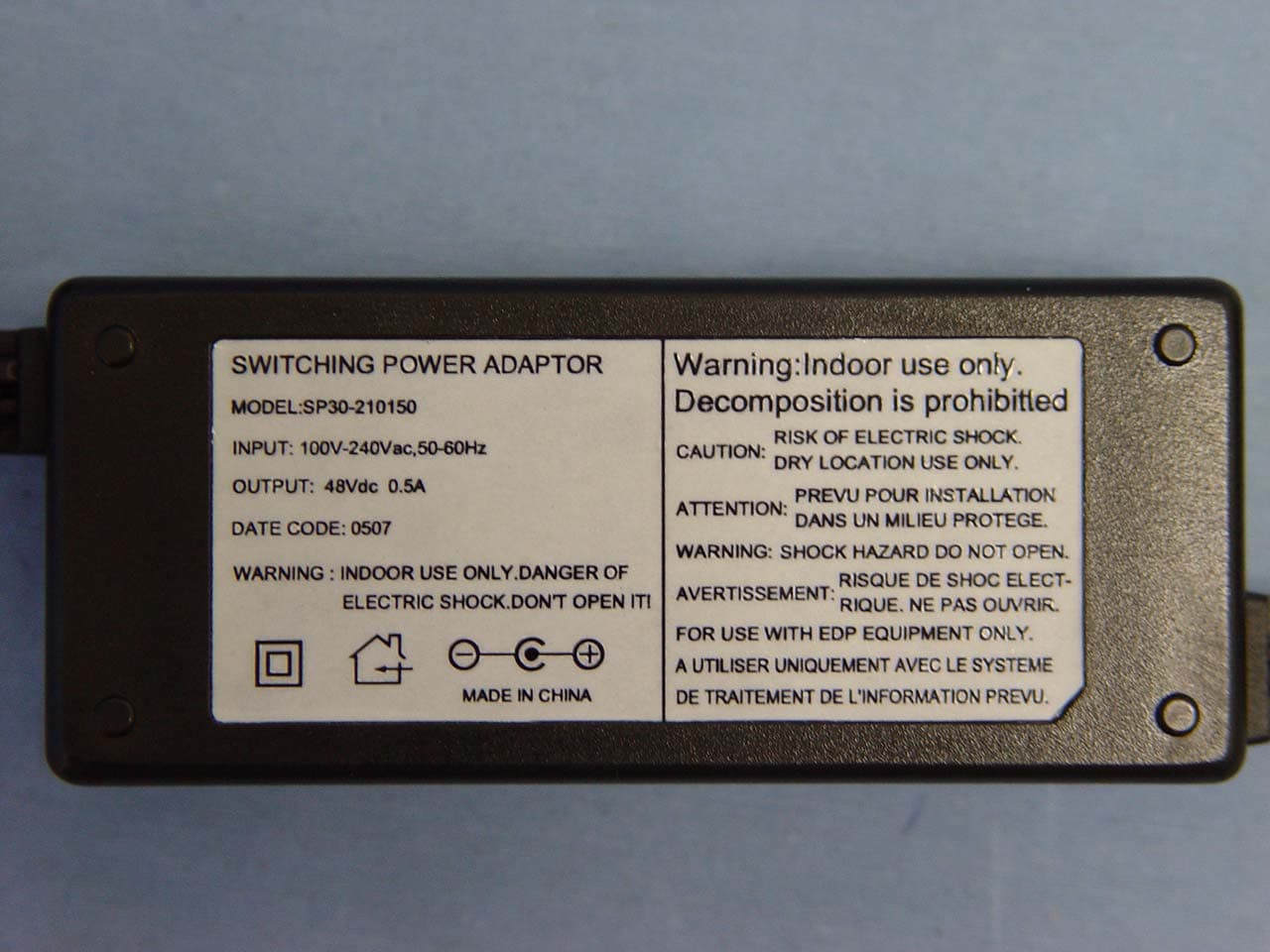
Click to zoom
Application Details
- Equipment Class
- DTS - Digital Transmission System
- Date of Grant
- Dec 14, 2005
- Application Purpose
- Original Equipment
- Date of Application
- Dec 14, 2005
- Equipment Note
- 802.11a High power Bridge
- Frequency Range
- 5745.00000000 - 5825.00000000
- Country
- United States
Documents & Files
Document Text
Text extracted from the exhibit documents filed with the FCC. Open a document above to read the original.
Users Manual
TT5800 Quick User Guide 802.11a 310mW Package Contains 1. TT5800 802.11a PCBA (1) 2. IEEE 802.11a miniPCI radio card (1) 3. Power over Ethernet Injector (1) 4. 48VDC Power Adapter (1) 5. Ethernet Cable (2) 6. Waterproof RJ-45 Connector (1) 7. Mounting Hardware (1) 8. 23dBi Subscriber antenna, 9. 20cm RF cable (cable loss: 8dB) 10. User Manual Quick Installation Always double check for any missing parts from the kit you received before deployment. Next step is to set up the computer Ethernet interface for configuring the TT5800. Since the default IP Address of the unit is on the 192.168.10.x IP range in both Client Bridge and AP mode you’ll need to set the computer Ethernet interface within the same IP range, such as 192.168.10.66. Hardware Installation Follow the procedure below to install your TT5800 device: 1. Select a suitable place on the network to install the TT5800. For best wireless reception and performance the external antenna should be positioned within Line of Sight from the AP with proper alignment. 2. Connect the TT5800 to the ODU side of the PoE Injector via a straight Ethernet cable (Cat-5), then connect the NET side of the PoE Injector to either a computer or an Ethernet Switch. Note: The TT5800 now fully supports the MDI/MDI-X standard and no longer require the use of cross over cable to connect directly with a computer. 3. Connect the 48VDC power adapter to the power jack on the PoE injector to power on the TT5800. Check the LEDs on the TT5800 to confirm if the status is okay. At this point the PWR and LAN LEDs should be on green. The WLAN light should light up once the unit is associated wirelessly with another wireless device. However at this point the unit is still in factory default setting so do not the alarmed that the WLAN light doesn’t light up. Web Control Interface Default IP Address in Client Bridge Mode: 192.168.10.241 Default IP Address in Access Point Mode: 192.168.10.240 Default Login / Password: Nothing needs to be typed in for login and password authentication. For detailed instructions on how to configure the TT-5800, please refer to www.teletronics.com/Support.html TT5800 is current designed to be configured only for the point-to-point operation mode, one access point (AP)and one access client (AC) are needed. Use in the following applications: z Financial banks and brokerage houses sensitive data transmission z Government agencies data connection among buildings z Central office to branch office(s) connection z Remote wireless monitoring z TT5800 has one antenna port, one data/power port and one console port. The antenna port is N-Type female connector used to connect to the RF cable then to the flat panel antenna. The data/power port is used to link to the cable from the power injector. When the TT5800 and the network/power injector are connected together, The TT5800 is turned on and initialized if the network/power injector in the indoor is also installed successfully. Warranty Policy Limited Warranty All Teletronics’ products warranted to the original purchaser to be free from defects in materials and workmanship under normal installation, use, and service for a period of one (1) year from the date of purchase. Under this warranty, Teletronics International, Inc. shall repair or replace (at its option), during the warranty period, any part that proves to be defective in material of workmanship under normal installation, use and service, provided the product is returned to Teletronics International, Inc., or to one of its distributors with transportation charges prepaid. Returned products must include a copy of the purchase receipt. In the absence of a purchase receipt, the warranty period shall be one (1) year from the date of manufacture. This warranty shall be voided if the product is damaged as a result of defacement, misuse, abuse, neglect, accident, destruction or alteration of the serial number, improper electrical voltages or currents, repair, alteration or maintenance by any person or party other than a Teletronics International, Inc. employee or authorized service facility, or any use in violation of instructions furnished by Teletronics International, Inc. This warranty is also rendered invalid if this product is removed from the country in which it was purchased, if it is used in a country in which it is not registered for use, or if it is used in a country for which it was not designed. Due to variations in communications laws, this product may be illegal for use in some countries. Teletronics International, Inc. assumes no responsibility for damages or penalties incurred resulting from the use of this product in a manner or location other than that for which it is intended. IN NO EVENT SHALL TELETRONICS INTERNATIONAL, INC. BE LIABLE FOR ANY SPECIAL, INCIDENTAL OR CONSEQUENTIAL DAMAGES FOR BREACH OF THIS OR ANY OTHER WARRANTY, EXPRESSED OR IMPLIED, WHATSOEVER. Some states do not allow the exclusion or limitation of special, incidental or consequential damages, so the above exclusion or limitation may not apply to you. This warranty gives you specific legal rights, and you may also have other rights that vary from state to state. RMA Policy Product Return Policy It is important to us that all Teletronics’ products are bought with full confidence. If you are not 100% satisfied with any product purchased from Teletronics you may receive a prompt replacement or refund, subject to the terms and conditions outlined below. IMPORTANT : Before returning any item for credit or under warranty repair, you must obtain a Return Merchandise Authorization (RMA) number by filling out the RMA form. Products will not be accepted without an RMA number. All products being shipped to Teletronics for repair/refund/exchange must be freight prepaid (customer pays for shipping). For all under warranty repair/replacement, Teletronics standard warranty applies. 30-Day full refund or credit policy: I. Product was purchased from Teletronics no more than 30 day pri…
Text truncated - open the document above for the full version.
Cover Letter(s)
Date: Nov 30 th ,2005 Compliance Certification Services Certification Division 561F Monterey Road Morgan Hill, CA 95037 To whom it may concern: We, the undersigned, hereby authorize the Taiwan office of Compliance Engineering Services, Inc., d.b.a. Compliance Certification Services and hereafter referred to as CCS TW, to act on our behalf in all manners relating to application for equipment authorization, including signing of all documents relating to these matters. Any and all acts carried out by CCS TW on our behalf shall have the same effect as acts of our own. We, the undersigned, hereby certify that we are not subject to a denial of federal benefits, that includes FCC benefits, pursuant to Section 5301 of the Anti-Drug Abuse Act of 1988, 21 U.S.C. 853(a). In authorizing CCS TW as our agent, we still recognize that we are responsible to: a) Comply with the relevant provisions of the certification program; b) Make all necessary arrangements for the conduct of the evaluation, including provision for examining documentation and access to all areas, records (including internal audit reports) and personnel for the purposes of evaluation (e.g. testing, inspection, assessment, surveillance, reassessment) and resolution of complaints; c) Make claims regarding certification only in respect of the scope for which certification has been granted; d) Do not use our product certification in such a manner as to bring the Certification Division into disrepute and not make any statement regarding our product certification which the Certification Division may consider misleading or unauthorized; e) Upon suspension or cancellation of certification, discontinue use of all advertising matter that contains any reference thereto and return any certification documents as required by the Certification Division; f) Use certification only to indicate the products are certified as being in conformity with specified standards; g) Endeavor to ensure that no certificate or report nor any part thereof is used in a misleading manner; h) Ensure that any reference to our product certification in communication media such as documents, brochures or advertising, complies with the requirements of the Certification Division; i) Keep a record of all complaints made known to the us relating to the product’s compliance with requirements of the relevant standard and to make these records available to the Certification Division when requested; j) Take appropriate action with respect to such complaints and any deficiencies found in products or services that affect compliance with the requirements for certification; k) Document the actions taken. This authorization is valid until further written notice from the applicant. Sincerely Yours, REMARK: 1. This authorization letter will be sent along with your application when filing with the Certification Division. 2. Please follow the format and type it on company letterhead and send original to us.
External Photos
Compliance Certification Services Inc. Report No: 50803106 Date of Issue: November 28, 2005 Page 1 Total Page: 10 Rev. 00 EXTERNAL PHOTOGRAPHS OF EUT Compliance Certification Services Inc. Report No: 50803106 Date of Issue: November 28, 2005 Page 2 Total Page: 10 Rev. 00 Compliance Certification Services Inc. Report No: 50803106 Date of Issue: November 28, 2005 Page 3 Rev.00 Compliance Certification Services Inc. Report No: 50803106 Date of Issue: November 28, 2005 Page 4 Rev.00 Compliance Certification Services Inc. Report No: 50803106 Date of Issue: November 28, 2005 Page 5 Rev.00
ID Label/Location Info
Teletronics International, Inc. Model: TT5800 Rating: 48VDC PoE Power FCC ID: MFMTT5800 This device complies with Part 15 of the FCC Rules. Operation is subject to the following two conditions: (1) this device may not cause harmful interference and (2) this device must accept any interference received, including interference that may cause undesired operation.
Internal Photos
Compliance Certification Services Inc. Report No: 50803106 Date of Issue: November 28, 2005 Page 6 Rev.00 INTERNAL PHOTOGRAPHS OF EUT Compliance Certification Services Inc. Report No: 50803106 Date of Issue: November 28, 2005 Page 7 Rev.00 Compliance Certification Services Inc. Report No: 50803106 Date of Issue: November 28, 2005 Page 8 Rev.00 Compliance Certification Services Inc. Report No: 50803106 Date of Issue: November 28, 2005 Page 9 Rev.00 Compliance Certification Services Inc. Report No: 50803106 Date of Issue: November 28, 2005 Page 10 Rev.00
Parts List/Tune Up Info
5.8GHz 23dBi Antenna Spec Electrical Frequency Range: 5.15 GHz - 5.85 GHz Transmit Gain: 23 dBi 3 dB BW Azimuth 9° (nom.) Elevation: 9° (nom.) Polarization: Linear, Vertical VSWR 1.7:1 (max) Sidelobes ETSI – TS3, Range 1 Cross Polarization - 20 dB (max.) Ft/B Ratio (max.) - 32 dB (max.) Lightning Protection DC Grounded General Type Subscriber Regulatory Compliance EN 302 085 v1.1.1 (1999) ETS 300 019 part 1-4 Environmental & Mechanical (Set up by professional) Connector: N-Type Female POINT TO POINT ANTENNA: Yes Operating Temperature: -40 °C to + 65 °C Antenna Dimensions: 12.1 x 12.1 x 1.57 inches Antenna Weight: 1.2 Kg Wind Load (survival) 136.62 Miles/Hr. Radial Ice Load 1 inch
Test Report
Compliance Certification Services Inc. Report No: 50803106-RP1 FCC ID: MFMTT5800 Date of Issue: November 28, 2005 Note: This report shall not be reproduced except in full, without the written approval of Compliance Certification Services Inc. This document may be altered or revised by Compliance Certification Services Inc. personnel only, and shall be noted in the revision section of the document. Page 1 Total Page: 50 Rev. 00 FCC 47 CFR PART 15 SUBPART C TEST REPORT For 802.11a High power Bridge Model: TT5800 Trade Name: TELETRONICS Issued to TELETRONICS TECHNOLOGY CO., LTD. 2 Choke Cherry Road Rockville, MD 20850, USA Issued by Compliance Certification Services Inc. No. 81-1, Lane 210, Bade Rd. 2, Luchu Hsiang, Taoyuan Hsien, (338) Taiwan, R.O.C. http://www.ccsemc.com.tw [email protected] Compliance Certification Services Inc. Report No: 50803106-RP1 FCC ID: MFMTT5800 Date of Issue: November 28, 2005 Page 2 Rev. 00 TABLE OF CONTENTS 1. TEST RESULT CERTIFICATION....................................................................................................3 2. EUT DESCRIPTION ...........................................................................................................................4 3. TEST METHODOLOGY ....................................................................................................................5 3.1 EUT CONFIGURATION........................................................................................................................5 3.2 EUT EXERCISE....................................................................................................................................5 3.3 GENERAL TEST PROCEDURES.............................................................................................................5 3.4 FCC PART 15.205 RESTRICTED BANDS OF OPERATIONS........................................................6 3.5 DESCRIPTION OF TEST MODES...........................................................................................................6 4. INSTRUMENT CALIBRATION........................................................................................................7 4.1 MEASURING INSTRUMENT CALIBRATION......................................................................................7 4.2 MEASUREMENT EQUIPMENT USED.........................................................................................7 5. FACILTIES AND ACCREDITATIONS............................................................................................8 5.1 FACILITIES....................................................................................................................................... 8 5.2 EQUIPMENT........................................................................................................................................8 5.3 LABORATORY ACCREDITATIONS AND LISTING..................................................................................8 5.4 TABLE OF ACCREDITATIONS AND LISTINGS.......................................................................................9 6. SETUP OF EQUIPMENT UNDER TEST .......................................................................................10 6.1 SETUP CONFIGURATION OF EUT.......................................................................................................10 6.2 SUPPORT EQUIPMENT ...............................................................................................................10 7. FCC PART 15.247 REQUIREMENTS.............................................................................................11 7.1 6DB BANDWIDTH.............................................................................................................................11 7.2 PEAK POWER....................................................................................................................................15 7.3 AVERAGE POWER............................................................................................................................20 7.4 PEAK POWER SPECTRAL DENSITY....................................................................................................24 7.5 SPURIOUS EMISSIONS ................................................................................................................28 7.6 POWERLINE CONDUCTED EMISSIONS...............................................................................................41 APPENDIX I RADIO FREQUENCY EXPOSURE ...............................................................................44 APPENDIX II PHOTOGRAPHS OF TEST SETUP .............................................................................48 Compliance Certification Services Inc. Report No: 50803106-RP1 FCC ID: MFMTT5800 Date of Issue: November 28, 2005 Page 3 Rev. 00 TEST RESULT CERTIFICATION Applicant: TELETRONICS TECHNOLOGY CO., LTD. 2 Choke Cherry Road Rockville, MD 20850, USA Equipment Under Test: 802.11a High power Bridge Trade Name: TELETRONICS Model: TT5800 Date of Test: November 17 ~ 22, 2005 APPLICABLE STANDARDS STANDARD TEST RESULT FCC 47 CFR Part 15 Subpart C No non-compliance noted We hereby certify that: The above equipment was tested by Compliance Certification Services Inc. The test data, data evaluation, test procedures, and equipment configurations shown in this report were made in accordance with the procedures given in ANSI C63.4: 2003 and the energy emitted by the sample EUT tested as described in this report is in compliance with the requirements of FCC Rules Part 15.207, 15.209, 15.247. The test results of this report relate only to the tested sample EUT identified in this report. Approved by: Reviewed by: Gavin Lim Amanda Wu Section Manager Section Manager Compliance Certification Services Inc. Compliance Certification Services Inc. Compliance Certification Services Inc. Report No: 50803106-RP1 FCC ID: MFMTT5800 Date of Issue: November 28, 2005 Page 4 Rev. 00 EUT DESCRIPTION Product 802.11a Hig…
Text truncated - open the document above for the full version.
Test Setup Photos
Compliance Certification Services Inc. Report No: 50803106-RP1 FCC ID: MFMTT5800 Date of Issue: November 28, 2005 Page 48 Rev. 00 APPENDIX II PHOTOGRAPHS OF TEST SETUP Conducted Emission Set Up Photo Compliance Certification Services Inc. Report No: 50803106-RP1 FCC ID: MFMTT5800 Date of Issue: November 28, 2005 Page 49 Rev. 00 Radiated Emission Set up Photos Compliance Certification Services Inc. Report No: 50803106-RP1 FCC ID: MFMTT5800 Date of Issue: November 28, 2005 Page 50 Rev. 00 Powerline Conducted Emissions Setup Photos
Contact Information
Applicant
Dickson Fang(President)
Test Firm
Compliance Certification Services Inc.Kurt Chen
Technical Specifications
| # | Rule Parts | Frequency Range | Power Output |
|---|---|---|---|
| 1 | 15C | 5.75 GHz - 5.83 GHz | 316.23 mW |
Other Applications from Teletronics International Inc

MFMTT-2400
Jun 05, 2006802.11b/g wLAN AP
Equipment Class
DTS - Digital Transmission System
MFMTT2400
Apr 24, 2006802.11b/g WLAN AP
Equipment Class
DTS - Digital Transmission System
MFM-11-136
Feb 23, 2004802.11b WLAN Card
Equipment Class
DTS - Digital Transmission System
MFMSAMP24S
Oct 20, 2002Wireless LAN System with Amplifier
Equipment Class
DTS - Digital Transmission System
MFMSAMP24W
Oct 10, 2002Wireless LAN System with Amplifier
Equipment Class
DTS - Digital Transmission System