MIJAD510Iridium Satellite Transceiver Active Antenna
General Dynamics Mission Systems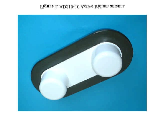
Click to zoom
Application Details
- Equipment Class
- AMP - Amplifier
- Date of Grant
- May 18, 2003
- Application Purpose
- Original Equipment
- Date of Application
- May 11, 2003
- Equipment Note
- Iridium Satellite Transceiver Active Antenna
- Frequency Range
- 1616.00000000 - 1626.50000000
- Country
- United States
Documents & Files
Document Text
Text extracted from the exhibit documents filed with the FCC. Open a document above to read the original.
Users Manual
AD510-10 Active Transmitter/Receiver Antenna with a 30m or 40m RG213U down-lead and DC regulator for Iridium Telephone Systems Introduction Iridium telephones were originally designed to operate with passive antennae, either an element attached directly to the handset, or a remote aerial connected with a short length of coaxial cable. Unfortunately, a signal loss of more than 3dB in a remote antenna’s connecting cable degrades performance due to attenuation of both the received and transmitted signals. A 3dB loss corresponds to approximately 10m of RG213U or 3m of RG58U coaxial cable, lengths that clearly restrict the mounting options for the antenna using standard down-leads. The AD510-10 active Iridium antenna (figures 1&2) is designed for use with 30m (98 feet) or 40m (131 feet) of RG213U coaxial cable terminated with type ‘N’ connectors. Designed for harsh environments, the AD510-10 consists of two RHCP dipole antennae housed within 4mm thick GRP radomes mounted on a common base. One antenna is for signal transmission and one for reception. A linear power amplifier within the base and connected to the transmitting antenna compensates for signal loss incurred mainly by the connecting cable. Similarly, a low noise amplifier is attached to the receiving antenna via a low loss interdigital filter to boost the signal sent to the telephone. The interdigital filter has a bandwidth of 12 MHz centred on the Iridium band designed to attenuate any out of band interference that may arise, for example from nearby Inmarsat uplinks. Using manufacturing techniques proven for a range of extremely rugged GPS/DGP active antennae, the antenna base is milled from aluminium and hard anodised, giving an attractive green finish, which is mechanically resilient and resistant to corrosion. The antenna’s mass is 2.6kg. Mounting and Operation (1) The AD510-10 should be mounted with an unobstructed view of the sky. An aluminium bracket with V-bolts is provided to attach the antenna to horizontal or vertical spars up to 60mm in diameter, figure 2. The bracket is shipped inverted on the end of the AD510-10 antenna and should be detached, turned over, then repositioned either to the centre or end of the antenna case as required using the mounting holes in the base. (2) The RG213U coaxial down-lead is attached to the N-type connector on the underside of the antenna, figure 2. Wrapping the connectors with self-amalgamating tape is recommended for permanent installations and the cable should be taped or strapped to the spar as appropriate. (3) AD510-10 antennae supplied with 40m RG213U down-leads must be used with the accompanying AD510-40 DC supply voltage regulators (figure 3), which accept +9V to +36V dc at 500mA. The down-lead must not be shortened by the user. Similarly, antennae supplied with 30m RG213U down-leads are only to be used with the AD510-30 DC supply voltage regulators provided. Again, the down-lead must not be shortened. In all other respects, however, the assembly and operation of the 30m cable systems are identical to those with 40m cables. (4) The AD510-40 (or AD510-30) supply voltage regulator should be positioned close to the telephone base-station or handset. The RG213U down-lead is then attached to the N type connector on the AD510-40 (figures 3 and 4). (5) Connection between the telephone and the AD510-40 is made with a coaxial cable terminated with TNCs. An adapter is provided with the Iridium handset, which enables a TNC terminated cable to be attached to the telephone. The AD510-40 case has drilled flanges to enable permanent fixing. (6) A 3m flying lead for the AD510-40 (or AD510-30) supply regulator is provided for connection to the DC supply (+9 to 36Vdc at 500mA), which can be trimmed (or extended) if necessary. The red wire is connected to supply positive, whilst the blue wire is for either an isolated or grounded negative supply. The AD510-40 (or AD510-30) is protected against output short-circuiting by a fuse, which is resettable by disconnecting the unit from the +9 to +36Vdc supply. (7) With all connections made, the telephone can then be turned on and used as normal- it is transmitting into a load impedance equivalent to a matched passive antenna. The gains of the antenna transmitter and receiver are factory set to compensate for the total attenuation between the telephone and the antenna, mainly determined by the RG213U down-lead. Consequently, the signal output level and frequency from the antenna is equivalent to that radiating from a passive antenna mounted directly on the handset, subject to the antenna transmitter being a linear device. Transmitter linearity is verified with test protocols using an HP 8591 EMC analyser that also ensure there are no spurious out of band emissions. Figure 1. AD510-10 Active Iridium antenna Figure 2. AD510-10 active Iridium antenna with mounting bracket and RG213U coaxial down-lead Figure 3. AD510-40 voltage regulator and break-in for use with +9 to 36Vdc supply. The case is hard anodised aluminium and has fixing flanges. A 40m coil of RG213U cable is shown connected to an AD510-10 active antenna (top). The handset interconnect is shown trailing from the TNC to the bottom left, whilst the flying lead for connection to 9 to 36V dc supply is shown cutting the frame to the right. Figure 4. Schematic diagram for system connections (1) Mount AD510-10 active antenna with clear view of sky using bracket supplied. (2) Attach top end of 40m (or 30m) down-lead to N type connector on underside of antenna. (3) Attach bottom end of down-lead to N type connector on voltage supply regulator AD510-40 (or AD510-30). The down-lead must not be shortened by the user . (4) Attach interconnect between TNC on AD510-40 (or AD510-30) and telephone (or base station) using the antenna adapter provided with the phone. (5) Attach DC supply lead to +9 to +36V DC supply (500mA max). Red lead to +supply, Blue to –supply. (6) Turn on Iridium telephone and log-in. END OF INSTR…
Text truncated - open the document above for the full version.
Cover Letter(s)
To: Gil Estrella @ GD-Decision Systems Subject: TCB Application FCC ID: MIJAD510 Gil: Review of the application is now complete, and a few issues remain to be addressed: ADMINISTRATIVE (1) A parts list is needed (can be held confidential). (2) A tune-up procedure is needed (can be held confidential) (3) A schematic is needed, which shows values for passive components (will be held confidential). The exhibit listed as a schematic is really a block diagram. (4) DC voltage and current into the final RF stage - cannot find, please indicate. (5) You have requested that the internal photos be held confidential. This requires additional justification, such as on the basis of professional installation - that is, the consumer does not have access to the enclosure (see FCC policy attached). (6) The exhibit named block diagram is really an external connection diagram; a block diagram is not needed, and this exhibit will not be used. TECHNICAL (1) Neither the Test Report not Report Addendum appear to show enough detail in the range 1559 - 1610 MHz to demonstrate compliance with 25.200(a): (a)1559 - 1605 MHz, eirp density < -70 dBW/MHz averaged over 20 ms, (RBW = 1 MHz for wideband signals) (b)1559 - 1605 MHz, eirp < - 80 dBW over 700 Hz for narrowband signals, averaged over 20 ms. There are only 3 prior Part 25 AMP filings in the FCC database. In all cases, demonstration of conformity to the 1600 MHz band limits was done in conjunction with the intended companion satellite phone. As a result, the Grants limit the use of the antenna to the specific phone. If you already have (or can get) sufficient data to demonstrate compliance without using the Iridium phone, the resulting Grant will not have this restriction. On the other hand, if it expedites completion by using the Iridium phone, it is acceptable to do so but the Grant will then restrict use of the antenna to the phone used for testing. Regards, Roland Gubisch ITS
Cover Letter(s)
From: Estrella Gil-P19838 [[email protected]] Sent: Monday, May 12, 2003 4:21 PM To: Roland Gubisch ITS/ES-Box Cc: TCB_Admin ITS/ES-Crt Subject: RE: Grant notes FCC ID: MIJAD510 Roland, Yes, your understanding of the power/gain for this antenna are correct. Reception is required from 0 (overhead) to roughly 82.5 degrees (i.e. 7.5 degrees above the horizon). The 8dBi is actually the best case scenario (max) for a 0 (overhead) to 20 degrees elevation and starts dropping off thereafter. The gain from 60 deg to 82.5 degrees is actually 3dBi (typ) or less and similar to the integral handset antenna. Regards, Gil Estrella GENERAL DYNAMICS Decision Systems 8201 E. McDowell Rd. M/S H2550 Scottsdale, AZ 85252 Phone: 480-441-3725 Pager: 602-360-4001 Fax: 480-441-3625 EMail: [email protected] -----Original Message----- From: Roland Gubisch ITS/ES-Box [mailto:[email protected]] Sent: Monday, May 12, 2003 8:55 AM To: Estrella Gil-P19838 Cc: TCB_Admin ITS/ES-Crt Subject: Grant notes FCC ID: MIJAD510 Good morning, Gil: Please confirm my understanding of the power/gain issues below. As output power above 1 GHz is usually specified in EIRP, I intend to generate the grant with a listing of EIRP as well as conducted power. a) the conducted power to the antenna is 0.63W, based on the 9.2% duty cycle and your measured data. b) antenna gain is 8 dBi, so the EIRP will be 4 W . c) this is higher EIRP than the phone by itself, owing to the higher antenna gain (compared to 0.5 - 1.5 dBi) at the same conducted power. Thank you, Roland Gubisch Intertek
External Photos
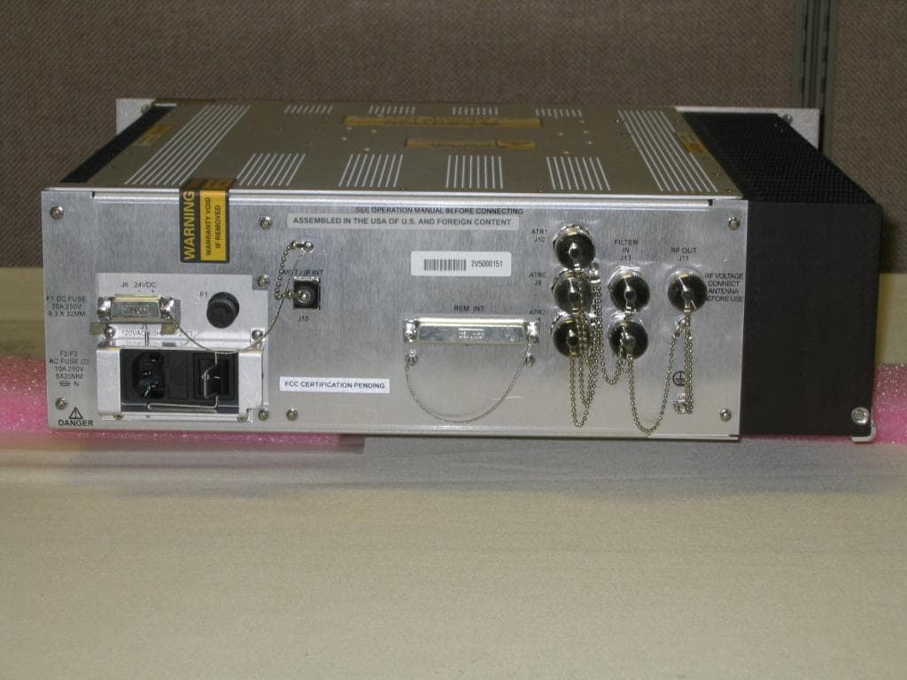
Exhibit 3 Page 1 of 2 FCC ID: MIJAD510 3/04/03 Exhibit 3 – External Photographs SATELLITE SYSTEMS DISTRIBUTION (SSD) Active Iridium Antenna FCC ID: MIJAD510 Model No. AD510-10 3.0 External Photos Figure 3.0-1 External View - Front Exhibit 3 Page 2 of 2 FCC ID: MIJAD510 3/04/03 Figure 3.0-2 AD510 External View - Rear
ID Label/Location Info
Exhibit 1 Page 1 of 1 FCC ID: MIJAD510 3/12/03 Exhibit 1 – ID Label Information SATELLITE SYSTEMS DISTRIBUTION (SSD) Active Iridium Antenna FCC ID: MIJAD510 Model No. AD510-10 1.0 Identification (Nameplate) Information Figure 1.0-1 AD510-10 Sample FCC Label Placement FCC ID: MIJAD510
Internal Photos
The information contained within this document is confidential to Satellite Systems Distribution and may not be disclosed in whole or in part without the written consent of its directors. Figure A2. Plate showing layout of components within AD510 base. The interdigital filter and LNA are to the right, the circulator and TX amplifier and ancillary components are mounted on the PCB centre left (see figure A3 for detail). Figure A3. Plate showing circuit board with circulator (1) and transmit amplifier (2). DC power for the amplifier is fed from the MCX input/output connector (3), through the circulator to a LM317T voltage regulator (4). RF is blocked by LC components (5). The RX signal is fed from the filter and LNA into the remaining port of the circulator (6), whilst the TX amplifier output is coupled through the PCB (7) and antenna base plate to the radiating element. The MCX connector (3) is attached to the N-Type connector on the antenna bottom case with a short flying lead. The information contained within this document is confidential to Satellite Systems Distribution and may not be disclosed in whole or in part without the written consent of its directors. AD510-40 DC voltage supply regulator components The internal components of the DC supply regulator are shown in figure A4. Figure A4. Plate showing circuit board carrying DC voltage regulator and ancillary components used in AD510-40. DC supply is via orange lead (1) and auto-reset fuse (2) to the voltage regulator pin input (10). The voltage regulator is a standard package (Texas Instruments PT5102A) and mounted on the reverse of the board. The stabilised supply is connected to 50 Ohm strip-line (3) with a coil inductor (4). (5), (6) are and (7) are capacitors, the latter providing a DC block to the Iridium handset connected via TNC (8). (9) is an N-type connector for the 40m antenna down-lead.
Test Report
Report No. 16324-1001-01 Exhibit 6 Page 1 of 16 FCC ID: MIJAD510 3/04/03 Exhibit 6 – Test Report SATELLITE SYSTEMS DISTRIBUTION (SSD) Active Iridium Antenna FCC ID: MIJAD510 Model No. AD510-10 Equipment Applicant: Satellite Systems Distribution (SSD) Burlingham House, Hewett Road Gapton Hall Estate, Great Yarmouth Norfolk, UK NR31 ONN Tests Conducted By: General Dynamics Decision Systems EMC Test Facility 8201 E. McDowell Rd. Scottsdale, Arizona 85252 Tests Date: January 28 th – March 4 th , 2003 Test Summary: Complies with FCC Part 25, Satellite Communications The General Dynamics Decision Systems EMC Laboratory is accredited through the NVLAP Lab Code 100405-0 This document shall not be reproduced, except in full, without the written approval of the laboratory. This document shall not be used by the client to claim product endorsement by NVLAP or any agency of the U.S. Government. Exhibit 6 Page 2 of 16 FCC ID: MIJAD510 3/04/03 6.0 Introduction 6.0.1 Product Description The IRIDIUM Subscriber Units (ISU) were originally designed to operate with passive antennae , either an element attached directly to the handset, or a remote aerial connected with a short length of coaxial cable. Unfortunately, a signal loss of more than 3dB in a remote antenna’s connecting cable degrades performance due to attenuation of both the received and transmitted signals. A 3dB loss corresponds to approximately 10m of RG213U or 3m of RG58U coaxial cable, lengths that clearly restrict the mounting options for the antenna using standard down- leads. The AD510-10 active Iridium antenna is designed for use with 30m (98 feet) or 40m (131 feet) of RG213U coaxial cable terminated with type ‘N’ connectors. Designed for harsh environments, the AD510-10 consists of two RHCP dipole antennae housed within 4mm thick GRP radomes mounted on a common base. One antenna is for signal transmission and one for reception. A linear power amplifier within the base and connected to the transmitting antenna compensates for signal loss incurred mainly by the connecting cable. Similarly, a low noise amplifier is attached to the receiving antenna via a low loss inter-digital filter to boost the signal sent to the telephone. The inter-digital filter has a bandwidth of 12 MHz centered on the Iridium band designed to attenuate any out of band interference that may arise. Using manufacturing techniques proven for a range of extremely rugged GPS/DGP active antennae, the antenna base is milled from aluminum and hard anodized, giving an attractive green finish, which is mechanically resilient and resistant to corrosion. The antenna’s mass is 2.6kg. 6.0.2 Facility Description All testing reported herein was performed at the General Dynamics Decision Systems (GDDS) EMI/TEMPEST Test Facility, located in Scottsdale, AZ. GDDS EMC Test Facility Address: GENERAL DYNAMICS Decision Systems Hayden EMC Facility, M/D H2550 8201 E. McDowell Rd. Scottsdale, AZ 85252-1417 The test facility includes a certified three-meter and ten-meter Open Area Test Site (OATS) and several shielded enclosures. The facility has been found to be in compliance with the requirements of Section 2.948 of the FCC rules, per Registration Number 90811, dated October 1, 2001. The facility has also been issued a Certificate of Accreditation through the National Voluntary Laboratory Accreditation Program (NVLAP) by NIST. This is under NVLAP Code: 100405-0 and is effective through September 30, 2003. The facility is in compliance with all CISPR 16 requirements. The NIST NVLAP accreditation is evidence of a quality test facility. However, with the exception of the standard Radiated Emissions Testing, the specific test methods required for certification of this equipment is not within the current NVLAP scope of accreditation. Exhibit 6 Page 3 of 16 FCC ID: MIJAD510 3/04/03 6.0.3 Quality System The EMI/TEMPEST Test Laboratory maintains a Quality Manual that describes the quality assurance program of the EMC/TEMPEST Facility to set forth procedures covering all quality assurance functions. This manual has been constructed to reflect a quality program in compliance with the requirements of the following: • National Institute of Standards & Technology (NIST) National Voluntary Laboratory Accreditation Program (NVLAP) • NIST/NVLAP EMC MIL-STD 462 Program Handbook (Apr. 1994) • NVLAP EMC and Telecommunications FCC Methods Handbook 150-11 (Apr. 1995) • MIL-Q-9858A, MIL-STD 461, 462, 463, 461D, 462D • National Security Agency Technical and Security Requirements Document for the Endorsed TEMPEST Test Services Program, NSA TSRD No. 88-8B, 5 Oct. 1993 6.0.4 Standard References 47 CFR 2 Code of Federal Regulations, Title 47, Part 2, “Frequency Allocations and Radio Treaty Matters; General Rules and Regulations” 47 CFR 25 Code of Federal Regulations, Title 47, Part 25, “Satellite Communications” Subpart C, "Technical Standards" C63.4-1992 American National Standards Institute (ANSI), “Methods of Measurement of Radio-Noise Emissions from Low-Voltage Electrical and Electronic Equipment in the Range of 9 kHz to 40 GHz” 6.1 Test Procedures 6.1.1 Requirements It was determined that the AD510-10, being an active antenna containing a power amplifier and LNA, is subject to the requirements relevant to an external amplifier or “booster”. This includes the standard spurious emissions requirements of Part 25, Subpart C, and additionally a non- typical 3-tone intermodulation test. . Exhibit 6 Page 4 of 16 FCC ID: MIJAD510 3/04/03 Table 6.1-1 Tests Required for Certification of the AD510 Antenna System Test Parameter FCC Part 2 Paragraph Number FCC Part 25 Paragraph Number FCC Part 25 Limit Radiated Spurious Emissions 2.1053 25.202 Frequency Offset Atten. 20.833-41.667 kHz 25 dBc 41.667-104.16 kHz 35 dBc > 104.67 kHz 43+10log(Pt) 3-Tone Intermodulation N/A N/A 82.3 dBuV/m (-13 dBm) 6.1.2 Operational Configuration The AD510-10 (S/N 011) active antenna system was configured for typical operation with the antenna int…
Text truncated - open the document above for the full version.
Test Report
Report No. 16324-1001-01 Addendum A Exhibit 6A Page 1 of 3 FCC ID: MIJAD510 4/14/03 Exhibit 6A – Test Report Addendum SATELLITE SYSTEMS DISTRIBUTION (SSD) Active Iridium Antenna FCC ID: MIJAD510 Model No. AD510-10 Exhibit 6A Page 2 of 3 FCC ID: MIJAD510 4/14/03 6.1A RF Power Output Data The conducted output power at the ISU transceiver has been measured at approximately +28 dBm average. The ISU transceiver has a 9.2% (8.28 ms Tx bursts/90 ms frame) transmit duty cycle. The RF losses from the ISU transceiver to the input of the AD510-10 antenna assembly have been measured at approximately –13.5dB using a HP8741ET network analyzer. The gain of the power amplifier has been measured at 14 dB with –0.4 dB loss through the isolator for a net gain of approximately +13.6 dB. Basically, the power amplifier in the AD510-10 is designed to compensate for the cable losses when using a longer cable drop from a remote antenna. The conducted power level at the output of the amplifier has been measured at approximately +27 dBm as shown by the graph on the foll owing page. - RF Output Power: 0.63 W - RF Input: .027 W
Test Report
Report No. 16324-1001-01 Addendum B Exhibit 6B Page 1 of 5 FCC ID: MIJAD510 4/28/03 Exhibit 6B – Test Report Addendum SATELLITE SYSTEMS DISTRIBUTION (SSD) Active Iridium Antenna FCC ID: MIJAD510 Model No. AD510-10 Exhibit 6B Page 2 of 5 FCC ID: MIJAD510 4/28/03 6.0B Global Navigation Satellite System Scans 6.1B Test Description The out-of-band emissions in the 1559-1610 MHz band were measured per 47 CFR Part 25, Section 25.216, to assure protection of aeronautical radionavigation-satellite services. The requirements are that the emissions do not exceed -70 dBW/MHz (-40 dBm/MHz) averaged over 20 msec, in the 1559-1605 MHz band or a level in the 1605-1610 MHz band determined by linear interpolation from –70 dBW/MHz at 1605 MHz to –10 dBW/MHz (+20 dBm/MHz) at 1610 MHz. The EIRP of discrete emissions of less than 700 Hz bandwidth from mobile earth stations shall not exceed –80 dBW (-50 dBm), averaged over 20 msec, in the 1559-1605 MHz band. 6.2B Test Measurement Procedure Since there was no direct interface to the power amplifier output of the AD510-10, these out-of- band emissions were measured using radiated emission measurement procedures. The measurements were conducted for both wideband and narrowband emissions using 1 MHz and 1 kHz bandwidths, respectively. Since typical receivers do not have 700 Hz bandwidths a 1 kHz bandwidth was used as a worst case scenario. The emissions were measured with the Iridium Subscriber Unit (ISU) transmitting at the maximum output power in Channels 3, 120, and 238. All three channels provided similar results. A gated average measurement was used to determine the emission levels with the sync pulse (frame tick) from the ISU connected to the external sync of the Rohde & Schwarz ESI7 Receiver. Initially, the carrier was maximized and subsequently the out-of-band emissions were measured in the 1559-1610 MHz bands. The worst case plots for these scans are shown in the attached pages. 6.3B Test Results The EIRP limits provided above can be converted to field strength in dBuV/m using the following equation: FS (dBuV/m) = EIRP (dbm) - 20 log (R) + 104.77 ; where R = 3 meters Therefore, the applicable limits for this test are as follows: EIRP (dBm) Field Strength (dBuV/m) -40 55.2 -50 45.2 -10 115.2 These limits are displayed on the attached graphs and indicate that the ISU, when used in conjunction with the AD510-10 active antenna, is compliant with the requirements for protection of the radionavigation-satellite services. The appropriate antenna factors have been included as a transducer factors as indicated by the “TDF” displayed to the right of the graph. The applicable cable loss was also included as an amplitude offset (4 dB was worst case across the band) to the levels measured from the AD510-10. Exhibit 6B Page 3 of 5 FCC ID: MIJAD510 4/28/03 Figure 6.0B-1 GNSS Wideband Out-of-Band Emissions, 1559-1605 MHz A UnitdBÊV/m 4 dB Offset GAT 1AV RF Att 0 dB Ref Lvl 55 dB* Ref Lvl 55 dB* Start1.559 GHzStop1.605 GHz4.6 MHz/ TDF RBW 1 MHz SWT 5 ms VBW 1 MHz 1AV IN1 1AVG 36 38 40 42 44 46 48 50 52 54 35 55 1 Marker 1 [T1] 52.13 dBÊV/m 1.60453908 GHz Date: 25.APR.2003 14:19:34 Exhibit 6B Page 4 of 5 FCC ID: MIJAD510 4/28/03 Figure 6.0B-2 GNSS Wideband Out-of-Band Emissions, 1605-1610 MHz A UnitdBÊV/m 4 dB Offset SWT 5 ms RBW 1 MHzRF Att 0 dB VBW 1 MHz IN1 1AV1AV GAT 1AVG Start1.605 GHzStop1.61 GHz500 kHz/ TDF Ref Lvl 101 dB* Ref Lvl 101 dB* 10 20 30 40 50 60 70 80 90 1 101 1 Marker 1 [T1] 52.20 dBÊV/m 1.60565130 GHz Date: 25.APR.2003 15:05:57 Exhibit 6B Page 5 of 5 FCC ID: MIJAD510 4/28/03 Figure 6.0B-2 GNSS Narrowband Out-of-Band Emissions, 1559-1605 MHz A UnitdBÊV/m 4 dB Offset RF Att 0 dBRBW 1 kHz SWT 115 s Ref Lvl 59 dB* Ref Lvl 59 dB* Start1.559 GHzStop1.605 GHz4.6 MHz/ TDF GAT 1AVG VBW 1 kHz IN1 1AV1AV 15 20 25 30 35 40 45 50 55 9 59 1 Marker 1 [T1] 24.93 dBÊV/m 1.60453908 GHz Date: 25.APR.2003 14:55:53
Test Setup Photos
Exhibit 7 Page 1 of 3 FCC ID: MIJAD510 3/04/03 Exhibit 7 – Test Setup Photos SATELLITE SYSTEMS DISTRIBUTION (SSD) Active Iridium Antenna FCC ID: MIJAD510 Model No. AD510-10 7.0 Test Setup Photographs Figure 7.0-1 Radiated Emissions Test Setup – Prescans & Harmonics Exhibit 7 Page 2 of 3 FCC ID: MIJAD510 3/04/03 Figure 7.0-2 Radiated Emissions Test Setup -OATS Exhibit 7 Page 3 of 3 FCC ID: MIJAD510 3/04/03 Figure 7.0-3 Radiated Emissions Test Setup -OATS
Contact Information
Applicant
Gil O. Estrella(EMC Engineer)
Technical Contact
General Dynamics Decision SystemsGil O Estrella
[email protected]480-441-3725
8201 E. McDowell Rd. · Scottsdale, Arizona · United States
Technical Specifications
| # | Rule Parts | Frequency Range | Power Output | Emission |
|---|---|---|---|---|
| 1 | 25 | 1.62 GHz - 1.63 GHz | 4 W | Q7W |
Other Applications from General Dynamics Mission Systems
MIJCM350V2
Aug 18, 2013CM-350 (V2) Air Traffic Control VHF Digital Transmitter (VDT)
Equipment Class
TNB - Licensed Non-Broadcast Station Transmitter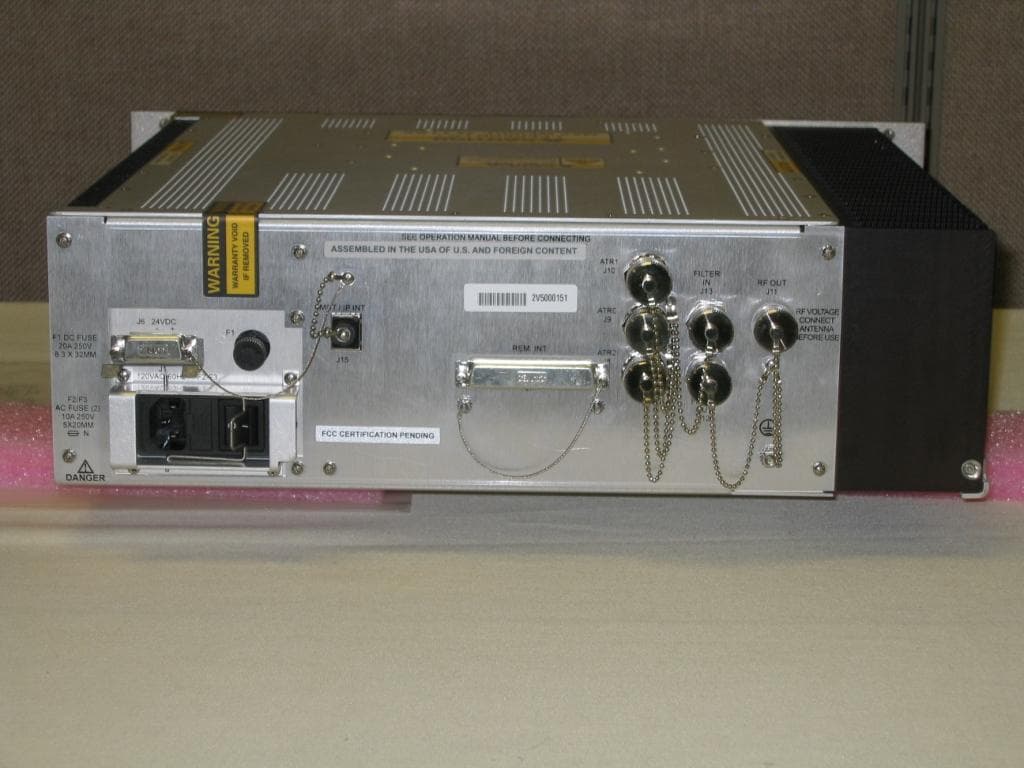
MIJCM300V2
Aug 18, 2013CM-300 (V2) Air Traffic Control VHF Digital Transmitter (VDT)
Equipment Class
TNB - Licensed Non-Broadcast Station Transmitter
MIJPNR-1000
May 08, 2012PathMaker Network Radio
Equipment Class
DTS - Digital Transmission System
MIJZEPCPE-USB-01
Mar 21, 2000Customer Premise Equipment - LMDS
Equipment Class
TNB - Licensed Non-Broadcast Station Transmitter
MIJTELCPE-USB-01
Mar 15, 2000Local Multipoint Distribution System
Equipment Class
TNB - Licensed Non-Broadcast Station Transmitter