MIJPNR-1000PathMaker Network Radio
General Dynamics Mission Systems
Click to zoom
Application Details
- Equipment Class
- DTS - Digital Transmission System
- Date of Grant
- May 08, 2012
- Application Purpose
- Original Equipment
- Date of Application
- Mar 15, 2012
- Equipment Note
- PathMaker Network Radio
- Frequency Range
- 2400.00000000 - 2483.50000000
- Country
- United States
Documents & Files
Document Text
Text extracted from the exhibit documents filed with the FCC. Open a document above to read the original.
Users Manual
Exhibit 8 Page 1 of 88 FCC ID: MIJPNR-1000 03/15/12 Exhibit 8 – User’s Manual General Dynamics C4 Systems PathMaker Network Radio FCC ID: MIJPNR-1000 Model No. PNR-1000 8.0 User’s Manual (Draft) 8220 East Roosevelt Street Scottsdale, AZ 85257 99-P42565K_Rev B Software Version 5.2 U U s s e e r r D D o o c c u u m m e e n n t t a a t t i i o o n n N N e e t t w w o o r r k k R R a a d d i i o o For customer support, please call or email: Toll Free: 877-230-0236 Local: 410-850-4893 DSN: 644-1139 Need email For more information, contact: GENERAL DYNAMICS C4 Systems 8220 E. Roosevelt Street, Scottsdale, AZ 85257 Domestic and International: +1 954-837-4855 Toll free (U.S. only): 888-920-1430 [email protected] © 2012 General Dynamics. All Rights Reserved. All trademarks indicated as such herein are trademarks of General Dynamics® Reg. U.S.P.T.O. All other product or service names are the property of their respective owners. General Dynamics Reserves the right to make changes in its products and specifications at any time and without notice. Printed in the U.S.A EXPORT CONTROL WARNING: Do not disclose or provide this document or item (including its contents) to non-U.S. Citizens or non-U.S. Permanent Residents, or transmit this document or item (including its contents) outside the United States without the written permission of General Dynamics and required U.S. Government export approvals. i Table of Contents CONTENTS Introduction ..................................................................................................................... 1 General Information ..................................................................................................... 2 Safety Precautions ....................................................................................................... 2 Modes and Features .................................................................................................... 5 List of Items Furnished ................................................................................................. 5 Accessories .................................................................................................................. 5 Electrical Characteristics .............................................................................................. 6 Environmental Operation and Storage ......................................................................... 7 System ......................................................................................................................... 8 Setup ............................................................................................................................. 10 Unpacking .................................................................................................................. 10 Charging the Battery .................................................................................................. 10 Operation ...................................................................................................................... 12 Equipment Description ............................................................................................... 12 Main Screen ............................................................................................................... 15 Display icons .............................................................................................................. 15 Function Keys ............................................................................................................ 17 General Information ................................................................................................... 17 Voice Communications .............................................................................................. 17 Text Communications ................................................................................................ 18 Data Communications ................................................................................................ 18 Voice Communications .............................................................................................. 18 Operating Procedures ................................................................................................ 19 Power ON/OFF ........................................................................................................................................................ 19 Selecting a Channel ................................................................................................................................................. 21 Volume Adjust......................................................................................................................................................... 22 Talk Select Using Menus ......................................................................................................................................... 23 ii Push-to-talk ............................................................................................................................................................. 24 Text Message .......................................................................................................................................................... 25 Talk Screen Options .................................................................................................. 27 Talk screen .............................................................................................................................................................. 27 Shortcuts ................................................................................................................................................................. 28 Prioritize Mode ....................................................................................................................................................... 29 Broadcast .......................…
Text truncated - open the document above for the full version.
Attestation Statements
Exhibit 2 Page 1 of 1 FCC ID: MIJPNR-1000 03/15/12 Exhibit 2 – Attestation Statement General Dynamics C4 Systems PathMaker Network Radio FCC ID: MIJPNR-1000 Model No. PNR-1000 2.0 Attestation Statement The technical data supplied with this application, having been taken under my supervision, is hereby duly certified. This is a statement of my qualifications: BSEE 1982, Northern Arizona University 28 years experience in EMC Engineering design and test Gil O. Estrella /s/ Name: Gil Estrella Date: 03/15/2012 Position: EMC Engineer
Cover Letter(s)
3/16/2012 CONFIDENTIALITY REQUEST CONTAINED WITHIN Federal Communications Commission Office of Engineering and Technology (OET) Equipment Authorization (EA) 7435 Oakland Mills Road Columbia, Maryland 21046 Re: Application for PathMaker Network Radio Certification – FCC ID: MIJPNR-1000 Gentlemen: General Dynamics C4 Systems, 8201 E. McDowell Rd, Scottsdale, Arizona 85257 herein submits this application for Equipment Authorization under FCC Rule Part 15, Subpart C, Intentional Radiators, for the PathMaker Network Radio FCC ID: MIJPNR-1000. In addition to confidentiality for the entire application prior to grant (per 47CFR0.457(d)(1)(ii)), General Dynamics requests, pursuant to 47 CFR 0.459, post-grant confidentiality for identified sections of the filing material contained in this application with this material being withheld from public inspection following the grant of this authorization. This material includes Exhibit 4 (Block Diagrams) and Exhibit 5 (Schematic Diagrams). Specifically, these exhibits contain information relating to circuit function and complexity that could be of benefit to competitors. This material contains manufacturer trade secrets and confidential information which is not customarily released to the public and which, otherwise, is not generally available to the public. Please contact me via telephone at (480) 441-3725 or by email at [email protected] if there are any further questions or additional information is needed regarding the filing. Sincerely, Gil O. Estrella /s/ Gil Estrella EMC Engineer GDC4S
External Photos
Exhibit 3 Page 1 of 3 FCC ID: MIJPNR-1000 03/15/12 Exhibit 3 – External Photos General Dynamics C4 Systems PathMaker Network Radio FCC ID: MIJPNR-1000 Model No. PNR-1000 3.0 External Photos Figure 3.0-1 PathMaker Radio External View (Front) Exhibit 3 Page 2 of 3 FCC ID: MIJPNR-1000 03/15/12 Figure 3.0-2 PathMaker Radio External View (Rear) Exhibit 3 Page 3 of 3 FCC ID: MIJPNR-1000 03/15/12 Figure 3.0-3 PathMaker Radio External View (Rear w/o Battery)
ID Label/Location Info
Exhibit 1 Page 1 of 2 FCC ID: MIJPNR-1000 03/15/12 Exhibit 1 – ID Label Information General Dynamics C4 Systems PathMaker Network Radio FCC ID: MIJPNR-1000 Model No. PNR-1000 1.0 Identification (Nameplate) Information Figure 1.0-1 Sample of PathMaker Network Radio FCC label Exhibit 1 Page 2 of 2 FCC ID: MIJPNR-1000 03/15/12 Figure 1.0-2 Location of PathMaker Network Radio FCC label Anticipated location of FCC ID Label
Internal Photos
Exhibit 9 Page 1 of 3 FCC ID: MIJPNR-1000 03/15/12 Exhibit 9 – Internal Photographs General Dynamics C4 Systems PathMaker Network Radio FCC ID: MIJPNR-1000 Model No. PNR-1000 9.0 Photographs Figure 9.0-1 RF PCB (Top) Exhibit 9 Page 2 of 3 FCC ID: MIJPNR-1000 03/15/12 Figure 9.0-2 RF PCB (Bottom) Figure 9.0-3 Control PCB (To p) Exhibit 9 Page 3 of 3 FCC ID: MIJPNR-1000 03/15/12 Figure 9.0-4 Control PCB (Bottom)
Operational Description
Exhibit 12 Page 1 of 1 FCC ID: MIJPNR-1000 03/15/12 Exhibit 12 – Operational Description General Dynamics C4 Systems PathMaker Network Radio FCC ID: MIJPNR-1000 Model No. PNR-1000 12.0 Operational Description PathMaker Network Radios provide dynamic wireless, mobile, ad-hoc networking communications without reliance on network infrastructure. PathMaker Radio users become their own network, which makes the radios ideal for use in remote locations where no infrastructure exists or where the infrastructure has been destroyed or overloaded. Where legacy network infrastructure exists, the PathMaker Network Radio System can take advantage of those networks by providing gateways, thereby increasing the network’s footprint and reach. With a maximum of 32 radio users per network, users can form traditional squad communications groups, or extend range and coverage by connecting to multiple networks. Users can communicate privately (one to one), as a group (one to many), and have multiple private and group sessions. The following diagram shows the basic system connectivity environment. Figure 2.1-1 PathMaker Network Radio System Context Diagram
RF Exposure Info
Exhibit 11 Page 1 of 31 FCC ID: MIJPNR-1000 03/15/12 Exhibit 11 – RF Exposure General Dynamics C4 Systems PathMaker Network Radio FCC ID: MIJPNR-1000 Model No. PNR-1000 11.0 PathMaker Network Radio SAR Analysis The PathMaker Network Radio is a re-branding of the Max Tech SAVION-E Mesh Communicator Unit. The two radios are identical in all respects with the exception of the nameplate. Both radios utilize the same exact housings, RF transmitter, RF modulator, and the same type of antennas. The SAVION-E Mesh Communicator Unit was tested for SAR by the Seibersdorf Laboratories in Seibersdorf, Austria during the time period from June 9 th to June 17 th , 2011. The attached Test Report NR EMV-E 17/11 contains the results of the SAR test. The unit was tested in voice mode in three different configurations including usage at the ear, front-of -face, and body worn. The worst case SAR measured was 0.238 W/kg as averaged across 1 gram in the body-worn configuration. This level is significantly less than the 47 CFR 15.247(i) and 47 CFR 2.1093 requirements of 1.6 W/kg as averaged across any 1 gram of tissue for the general public. The SAR test measurements were performed with a half-wave dipole, “rubber duck”, antenna having a maximum +2 dBi gain. This antenna was the P/N ANT-2.4-CW-QW manufactured by Antenna Factor. The antenna to be provided with the radio is of the same family, i.e. a half- wave dipole, “rubber duck”, antenna having similar gain (+2 dBi). This antenna is the ENTEL P/N 85-P42580K. The drawings for both antennas are included after the attached SAR test report. The antenna change was implemented in order to provide a unique antenna connector, Reverse Thread (RT) SMA, to satisfy the 47 CFR Part 15.203 requirements. The PathMaker Network Radio includes a data mode capability which has a higher duty cycle of transmission than the voice mode. An analysis was performed to calculate the resulting worst case SAR from the PathMaker radio when used in data mode. A time domain plot of the voice mode is shown in Figure 1, which was extracted from the SAVION-E SAR Test Report. There are three pulses that occur in every 100 ms frame. The first pulse has a width of about 0.8 ms whereas the second and third pulses each have a width of about 1.1 ms. The resultant duty cycle in voice mode is (0.8 + 1.1 + 1.1)/100 = 0.03 or 3%. Exhibit 11 Page 2 of 31 FCC ID: MIJPNR-1000 03/15/12 Figure 1 – Plot of Pulse Frame in Voice Mode from Figure 3.3 of Test Report NR EMV-E 17/11 The time domain plot of the data mode is shown in Figure 2. There are several 100ms frames shown in this plot to depict the behavior in data mode. As can be seen in this plot, the frames alternate between having three-pulse frames and having eight-pulse frames. The frames with three pulses are similar to the voice mode frames. A close-up plot of frames that contain eight pulses is shown in Figure 3. The eight pulse frame consists of one pulse that is 0.8 ms wide and seven pulses that are 1.1 ms wide. Contains 3 pulses Contains 8 pulses Figure 2 – Plot of Several Pulse Frames in Data Mode Exhibit 11 Page 3 of 31 FCC ID: MIJPNR-1000 03/15/12 Figure 3 – Close-Up Plot of Frame with Eight Pulses The duty cycle in data mode can be calculated as follows. {(0.8 + 1.1 + 1.1) + (0.8 + 1.1 +1.1 +1.1 +1.1+1.1 +1.1 +1.1)}/200 = 0.0575 or 5.75%. We can calculate the worst case SAR in data mode by scaling the voice mode SAR according to the ratio of the duty cycles for data mode and voice mode. This is calculated as follows. Data Mode SAR = 0.238 W/kg * 5.75%/3% = 0.456 W/kg as averaged across one gram of tissue. This worst case level of 0.456 W/kg is compliant with the FCC limit of 1.6 W/kg from 47CFR2.1093. Based on this analysis with supporting test data shown in the attached Test Report NR EMV-E 17/11, we can conclude that the PathMaker is compliant with the SAR requirements for portable devices. EMC Testing Laboratory Test Report NR. EMV-E 17/11 Page 2 of 26 Seibersdorf Labor GmbH | 2444 Seibersdorf, Austria | Tel.: +43 (0) 50550-2500 | Fax: +43 (0) 50550-2502 | Mail: [email protected] www.seibersdorf-laboratories.at | Landesgericht Wiener Neustadt | FN 319187v | DVR: 4000728 | UID: ATU64767504 | Steuernummer: 192/6571 | Zertifiziert nach ISO 9001:2000 Bankverbindung: Erste Bank der Österreichischen Sparkassen AG | BLZ 20111 | Konto Nr. 291-140-380/00 | IBAN AT112011129114038000 | BIC GIBAATWW 1. Summary Tables 1.1 to 1.3 summarize the maximum values of the 10g-averaged and 1g-averaged spatial peak specific absorption rate (maxSAR10g) assessed at the SAM phantom according to IEC 62209-1 for DUT use at the ear and at the elliptic flat body phantom according to IEC 62209-2 for body worn or front of face usage of the DUT. The test results summarized below refer to the condition with the DUT’s push-to-talk button pressed, corresponding to a time averaged DUT output power of approximately 15 mW (measured at the antenna connector into 50 Ω). Usage at the ear (SAM phantom) maxSAR10g maxSAR1g 0.169 W/kg 0.206 W/kg Table 1.1: Maximum spatial peak average SAR values for DUT usage at the ear (IEC 62209-1) Front-of-Face (25 mm distance between device and flat phantom) maxSAR10g maxSAR1g 0.075 W/kg 0.093 W/kg Table 1.2: Maximum spatial peak average SAR values in Front-of-Face condition (IEC 62209-2) On Body Use / Hand Use (DUT case touching the flat phantom shell) maxSAR10g maxSAR1g 0.170 W/kg 0.238 W/kg Table 1.3: Spatial peak average SAR values in Hand Exposure and Back-Use condition (IEC 62209-2) In all considered conditions according to IEC 62209-1 and IEC 62209-2 the DUT did not exceed the applicable basic restrictions for localized exposure of the general public (i.e., 2 W/kg for head and trunk, in terms of maxSAR10g) according to the ICNIRP Guidelines 1998 [1] as well as uncontrolled environments according to IEEE Std. C95.1-2005 [2]. EMC Testing Laboratory Test Report NR. EMV-E 17/11 Page 3 of 26 Seibersdorf Labor GmbH | 2444 Seibersd…
Text truncated - open the document above for the full version.
Test Report
Exhibit 6 Page 1 of 40 FCC ID: MIJPNR-1000 03/15/12 Exhibit 6 – Test Report General Dynamics C4 Systems PathMaker Network Radio FCC ID: MIJPNR-1000 Model No. PNR-1000 Equipment Applicant: General Dynamics C4 Systems 8220 E. Roosevelt St. Scottsdale, Arizona 85257 Tests Conducted By: General Dynamics C4 Systems EMC Test Facility 8201 E. McDowell Rd. Scottsdale, Arizona 85257 Te s t S ummary: Complies with FCC Part 15, Subpart C, Unlicensed Transmitter The General Dynamics EMC Laboratory is accredited through the NVLAP Lab Code 100405-0 This document shall not be reproduced, except in full, without the written approval of the laboratory. This document shall no be used by the client to claim product endorsement by NVLAP or any agency of the U.S. Government. 75267-01000 2 OF 40 PathMaker Network Radio REV: - 03/02/2012 TEST SUMMARY SHEET Specification Requirement Test Performed Test Results (Pass/Fail) 6dB Emission Bandwidth 47 CFR 15.247(a)(2) Pass Maximum Conducted Output Power 47 CFR 15.247(b)(3) Pass Power Spectral Density 47 CFR 15.247(e) Pass Conducted Spurious Emissions 47 CFR 15.247(d) Pass Radiated Spurious Emissions including Restricted Bands of Operation 47 CFR 15.247(d) and 15.209(a) Pass The laboratory is accredited by NIST NVLAP for the standard FCC Radiated Emissions test methods. The other tests are non-standard, RF Characteristic, tests required only for this specific type of intentional radiator. The test results shown in this report are only valid for the specific item tested. Other units may have different results. It is the policy of the General Dynamics EMC Laboratory to provide uncertainty data sheets for all compliance related measurements. Table 1 of CISPR 16-4-2 defines an upper limit on expanded uncertainty (U CISPR ) of 5.2dB for radiated emissions from 30MHz to 1GHz. The General Dynamics EMC Lab has an expanded uncertainty (U LAB ) of 3.91dB for radiated emissions. According to CISPR 16-4-2, if U LAB is less than U CISPR , then demonstration of compliance to the limits does not require an additional safety margin to account for measurement uncertainty. For all tests other tests, the test limits as defined by the appropriate standards organizations are assumed to already include a reasonable amount of uncertainty built into the limits to account for measurement uncertainty and therefore, demonstration of compliance to the limits does not require an additional safety margin to account for measurement uncertainty. 75267-01000 3 OF 40 PathMaker Network Radio REV: - 03/02/2012 TABLE OF CONTENTS TABLE OF CONTENTS ....................................................................................................................... 3 1.0 GENERAL INFORMATION ....................................................................................................... 4 1.1 INTRODUCTION .................................................................................................................. 4 1.2 APPLICABLE RULES ........................................................................................................... 4 1.3 TEST METHODOLOGY ....................................................................................................... 4 1.4 TEST FACILITY .................................................................................................................... 5 1.5 QUALITY SYSTEM .............................................................................................................. 5 2.0 TEST SAMPLE DESCRIPTION ................................................................................................. 6 2.1 THEORY OF OPERATION ................................................................................................... 6 2.2 LIST OF EQUIPMENT TESTED .......................................................................................... 7 3.0 TEST SETUP AND METHODOLOGY ...................................................................................... 7 3.1 SYSTEM TEST MODES AND CONFIGURATIONS .......................................................... 7 3.2 PERIPHERALS AND INTERFACE CABLES ..................................................................... 7 3.3 EQUIPMENT MODIFICATIONS ......................................................................................... 7 3.4 POWER REQUIREMENTS ................................................................................................... 8 3.5 DUTY CYCLE CORRECTION FACTOR FOR RADIATED EMISSIONS ........................ 8 3.6 ANTENNA REQUIREMENTS ........................................................................................... 11 3.7 ATMOSPHERIC CONDITIONS ......................................................................................... 11 4.0 TEST RESULTS ......................................................................................................................... 12 4.1 6 DB EMISSION BANDWIDTH ......................................................................................... 12 4.2 MAXIMUM CONDUCTED OUTPUT POWER ................................................................. 14 4.3 POWER SPECTRAL DENSITY .......................................................................................... 16 4.4 CONDUCTED SPURIOUS EMISSIONS INCLUDING BAND EDGES .......................... 19 4.5 RADIATED EMISSIONS, ELECTRIC FIELD, FCC, 30MHZ - 25GHZ ........................... 24 5.0 CONCLUSIONS ......................................................................................................................... 32 ATTACHMENT 1: ESTIMATE OF UNCERTAINTY ...................................................................... 33 ATTACHMENT 2: TEST SETUP PHOTOS ..................................................................................... 36 75267-01000 4 OF 40 PathMaker Network Radio REV: - 03/02/2012 1.0 GENERAL INFORMATION 1.1 INTRODUCTION This document describes the applicable Federal Communications Commission (FCC) certification te…
Text truncated - open the document above for the full version.
Test Setup Photos
Exhibit 7 Page 1 of 2 FCC ID: MIJPNR-1000 03/15/12 Exhibit 7 – Test Setup Photographs General Dynamics C4 Systems PathMaker Network Radio FCC ID: MIJPNR-1000 Model No. PNR-1000 7.0 Test Setup Photographs Figure 7.0-1 Front-End Conducted Emissions Test Setup Exhibit 7 Page 2 of 2 FCC ID: MIJPNR-1000 03/15/12 Figure 7.0-2 Radiated Emissions Test Setup
Contact Information
Applicant
Gil O. Estrella(EMC Engineer)
Technical Contact
General DynamicsGil O Estrella
[email protected]4804413725
8201 E. McDowell Rd · Scottsdale, Arizona · United States
Test Firm
General Dynamics C4 SystemsHarry Gaul
Technical Specifications
| # | Rule Parts | Frequency Range | Power Output |
|---|---|---|---|
| 1 | 15C | 2.40 GHz - 2.48 GHz | 500.00 mW |
Other Applications from General Dynamics Mission Systems
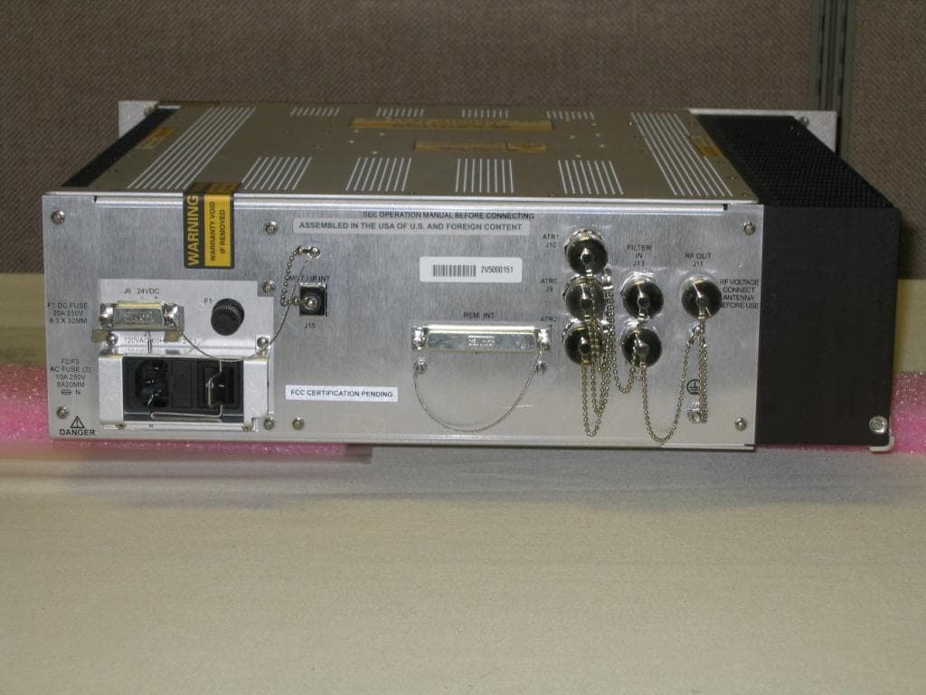
MIJCM350V2
Aug 18, 2013CM-350 (V2) Air Traffic Control VHF Digital Transmitter (VDT)
Equipment Class
TNB - Licensed Non-Broadcast Station Transmitter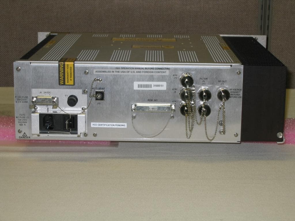
MIJCM300V2
Aug 18, 2013CM-300 (V2) Air Traffic Control VHF Digital Transmitter (VDT)
Equipment Class
TNB - Licensed Non-Broadcast Station Transmitter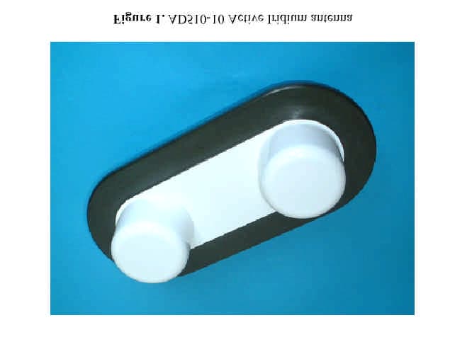
MIJAD510
May 18, 2003Iridium Satellite Transceiver Active Antenna
Equipment Class
AMP - Amplifier
MIJZEPCPE-USB-01
Mar 21, 2000Customer Premise Equipment - LMDS
Equipment Class
TNB - Licensed Non-Broadcast Station Transmitter
MIJTELCPE-USB-01
Mar 15, 2000Local Multipoint Distribution System
Equipment Class
TNB - Licensed Non-Broadcast Station Transmitter