MIJZEPCPE-USB-01Customer Premise Equipment - LMDS
General Dynamics Mission Systems
Click to zoom
Application Details
- Equipment Class
- TNB - Licensed Non-Broadcast Station Transmitter
- Date of Grant
- Mar 21, 2000
- Application Purpose
- Original Equipment
- Date of Application
- Dec 28, 1999
- Equipment Note
- Customer Premise Equipment - LMDS
- Frequency Range
- 31225.00000000 - 31300.00000000
- Country
- United States
Documents & Files
Document Text
Text extracted from the exhibit documents filed with the FCC. Open a document above to read the original.
Users Manual
Exhibit 8 Page 1 of 1 FCC ID: MIJZEPCPE-USB-01 12/30/99 Ground Systems Division Exhibit 8 – User Manual Motorola Customer Premise Equipment (CPE) FCC ID: MIJZEPCPE-USB-01 Model No. LT 20M-00 8 Product Functional Requirements (User Manual) 8.1 Scope The requirements described herein are functional in nature and describe Zephyr product features required to meet LMDS Service Provider expectations. Development Engineering will generate technical specifications which trace to or are derived from the requirements defined herein. Product qualification shall demonstrate and verify that the following product requirements are met. 8.2 Introduction Section 8.2, 8.2.1, 8.2.2, 8.2.3 and 8.2.4 are provided for information only. Requirements are defined in detail in sections 8.3 and 8.4 in their entirety. LMDS Systems utilize Customer Premise Equipment (CPE) to provide an interface for system subscribers to input data to and receive data from the system. The CPE functional block diagram is shown in Figure 8.2-1. In order to input user data to the LMDS system: • User data is input to the Indoor Unit (IDU). • The IDU generates an upstream IF signal modulated with user data. • The upstream IF is input to the Zephyr Outdoor Unit (ODU) through the Power Control Unit (PCU). • The ODU up converts the upstream IF to the upstream carrier frequency for over the air transmission to the LMDS hub. In order to receive data from the LMDS system: • The ODU down converts the received over the air downstream signal to the downstream receive IF. • The downstream IF is input to the IDU through the PCU. • The IDU demodulates the IF signal and recovers the user data. • Data is output to the user. The physical interface between the IDU and PCU is a single cable. Similarly, the physical interface between the PCU and ODU is a single cable. The IDU is a DOCSIS compliant cable MODEM. Exhibit 8 Page 2 of 2 FCC ID: MIJZEPCPE-USB-01 12/30/99 In order to communicate with the Outdoor Unit to perform service or installation tasks, a serial communication path is provided from the ODU through the PCU to an attached personal computer. The PC executes an application program known as Radio Service Software. Based on operator selections, the PC can query the ODU to determine health status, configuration, etc. The Zephyr Product is a major portion of the subscriber CPE as indicated by the dashed line in Figure 8.2-1. The Zephyr Subsystem contains the following components: 1. Zephyr ODU 2. Zephyr Firmware 3. Zephyr Power Control Unit (PCU) 4. Zephyr Radio Service Software Zephyr Outdoor Unit (ODU) Headend or Repeater Indoor Unit Bias-T Power Control Unit (PCU) Zephyr Firmware PC Application: Radio Service Software Zephyr Subsystem Contained in Dashed Line Serial Com Intfac User Data I/O (Cable MODEM) AC Line Power Interface PCU/IDU IF Figure 8.2-1 ODU /PCU IF PC Required for Maintenance/ Service Only, not required for normal operation 8.2.1 Zephyr Outdoor Unit ODU The Zephyr ODU is a microwave transceiver, it performs two primary functions: 1. The ODU up converts the upstream IF generated by the Indoor Unit for over the air transmission to the LMDS Hub. 2. The ODU down converts over the air signals transmitted by the LMDS Hub to a receive IF and outputs the signal to the Indoor Unit for demodulation and data recovery. Exhibit 8 Page 3 of 3 FCC ID: MIJZEPCPE-USB-01 12/30/99 Additionally, the ODU provides a serial communication interface to a personal computer attached through the PCU. The personal computer is used for service or ODU equipment programming, it is not required for normal operation. The ODU interfaces to the Indoor Unit through the Power Control Unit using a single coaxial cable connection. Upstream IF, Downstream IF, Power supply voltage and the serial communication interface to the ODU are multiplexed over the coaxial cable connection. The transceiver will typically be located outdoors and must operate in various harsh environments. 8.2.2 Zephyr Firmware The Zephyr ODU contains a microcontroller. The microcontroller executes embedded firmware to manage transceiver functions. The Zephyr firmware is reprogrammable through the serial communication interface. 8.2.3 Zephyr Power Control Unit (PCU) The Zephyr PCU performs several functions: 1. The PCU converts line voltage to the DC supply voltage required to power the ODU. 2. The PCU combines the DC supply voltage with the Indoor Unit IF interface for input to the ODU via the IF interface. 3. The PCU provides a MODEM function to allow a PC to interface to the ODU via the IF interface. The Power Control Unit is located indoors. As such, its operating environment is benign. 8.2.4 Zephyr Radio Service Software Radio Service Software is a PC application program that communicates with the ODU via the serial communication interface. The application program provides a user interface to download firmware, reprogram/read radio configuration data and determine rudimentary health status. Radio Service Software is to be used by Maintenance/Repair Depots and Service Provider technicians, it is not to be made available to equipment end users. 8.3 Zephyr Subsystem Requirements This section defines requirements for the combination of the Zephyr components. 8.3.1 Interoperability The Zephyr subsystem is one system element of the overall LMDS system. As such, it is required to interoperate with other system elements. 8.3.1.1 Hub and Router The Zephyr Subsystem shall operate with the Motorola DOCSIS compatible Cable Router and the Millitech B Band Headend Sector Unit. 8.3.1.2 DOCSIS MODEM The Zephyr Subsystem shall operate with DOCSIS compatible cable MODEMs. Exhibit 8 Page 4 of 4 FCC ID: MIJZEPCPE-USB-01 12/30/99 8.3.2 Unit Production Cost The unit production cost of the Zephyr B band subsystem, which includes the ODU and PCU components only, shall be less than $1,020 U.S. 8.3.3 Reliability The Mean Time Between Failure (MTBF) of the Zephyr subsystem shall exceed 30,000 hours. 8.3.4 Regulatory Require…
Text truncated - open the document above for the full version.
Attestation Statements
Ground Systems Division Exhibit 2 Page 1 of 1 FCC ID: MIJZEPCPE-USB-01 12/29/99 Exhibit 2 – Attestation Statement Motorola Customer Premise Equipment (CPE) FCC ID: MIJZEPCPE-USB-01 Part No. LT 20M-00 2.0 Attestation Statement The technical data supplied with this application, having been taken under my supervision, is hereby duly certified. This is a statement of my qualifications: BSEE 1974, University of Michigan, Ann Arbor, Michigan 25 years experience in EMC Engineering design and test Name: James Dykema Date: 12/29/99 Position: Sr. Staff Engineer I hereby certify that the above application was prepared under my direction and that to the best of my knowledge and belief, the facts set forth in the application and accompanying technical data are true and correct. Name: Dwayne Awerkamp Date: 12/29/99 Position: EMC Department Manager
Cover Letter(s)
Systems Solutions Group CONFIDENTIALITY REQUEST CONTAINED WITHIN Federal Communications Commission Authorization and Evaluation Division 7435 Oakland Mills Road Columbia, Maryland 21046 Re: Application for LMDS Certification – MIJZEPCPE-USB-01 Gentlemen: Motorola, Inc., Systems Solutions Group, 8201 E. McDowell Rd, Scottsdale, Arizona 85252 herein submits: Remittance Advice (FCC Form 159 – per US Mail with Fee Codes EFT and EBC, $610.00 VISA), Application for Equipment Authorization (FCC Form 731 – Electronic Filing), and Exhibits (Electronic Filing) for Certification of the Local Multipoint Distribution System (LMDS), under FCC Rule Part 101, FCC ID: MIJZEPCPE-USB-01. Motorola produces the Zephyr Customer Premise Equipment (CPE) to operate with equipment from Telaxis Communications. Telaxis (formerly, Millitech Inc.) is located at 20 Industrial Drive East, South Deerfield, MA 01373-0109. This application is for the Zephyr CPE. Separate applications have been submitted for the Telaxis produced Head-end Transceiver (HUB) (FCC ID: MIJTELHUB-USB-01) and CPE (FCC ID: MIJTELCPE-USB-01) In addition to confidentiality for the entire application prior to grant (per 47CFR0.457(d)(1)(ii)), Motorola requests, pursuant to 47CFR0.459, post-grant confidentiality for identified sections of the filing material contained in this application with this material being withheld from public inspection following the grant of this authorization. This material includes Exhibit 4, Block Diagrams, and Exhibit 5, Schematic Diagrams. Specifically, these exhibits contain information relating to circuit function and complexity that could be of benefit to competitors. This material contains Motorola’s trade secrets and confidential information which is not customarily released to the public and which, otherwise, is not generally available to the public. Please contact me by telephone at (480) 675-2104, by facsimile at (480) 441-3625, or by email at [email protected] if there are any further questions or additional information needed regarding the filing. Sincerely, Jim Dykema EMC Engineer Motorola SSG
External Photos
Ground Systems Division Exhibit 3 Page 1 of 1 FCC ID: MIJZEPCPE-USB-01 12/29/99 Exhibit 3 – External Photos Motorola Customer Premise Equipment (CPE) FCC ID: MIJZEPCPE-USB-01 Model No. LT 20M-00 3.0 External Photos Figure 3.0-1 CPE External View (for horizontal polarization) Exhibit 3 Page 2 of 2 FCC ID: MIJZEPCPE-USB-01 12/29/99 Figure 3.0-2 CPE External View (for vertical polarization) Exhibit 3 Page 3 of 3 FCC ID: MIJZEPCPE-USB-01 12/29/99 Figure 3.0-3 CPE External Rear View
ID Label/Location Info
Ground Systems Division Exhibit 1 Page 1 of 2 FCC ID: MIJZEPCPE-USB-01 12/29/99 Exhibit 1 – ID Label Information Motorola Customer Premise Equipment (CPE) FCC ID: MIJZEPCPE-USB-01 Model No. LT 20M-00 1.0 Identification (Nameplate) Information Figure 1.0-1 Detailed view of Zephyr FCC label Exhibit 1 Page 2 of 2 FCC ID: MIJZEPCPE-USB-01 12/29/99 Figure 1.0-2 Location of Zephyr FCC label
Operational Description
Exhibit 12 Page 1 of 1 FCC ID: MIJZEPCPE-USB-01 12/29/99 Ground Systems Division Exhibit 12 – Operational Description Motorola Customer Premise Equipment (CPE) FCC ID: MIJZEPCPE-USB-01 Model No. LT 20M-00 12.0 Operational Description The hardware for FCC Certification submittal is the Motorola LMDS Zephyr Outdoor Unit (Zephyr ODU). In order to facilitate the operational description of the Zephyr ODU, other elements of the total LMDS system will be introduced. But these additional elements support the operational description and are not part of the FCC Certification submittal. LMDS Systems utilize Customer Premise Equipment (CPE) to provide an interface for system subscribers to input data to and receive data from the system. The CPE functional block diagram is shown in Figure 12.0-1. Note that the Zephyr ODU is only one element of the Customer Premise Equipment and is that element that transmits and receives communications between other elements of the LMDS System. In order to input user data to the LMDS system by RF transmission via the Zephyr ODU as follows: • User data is input to the Indoor Unit (IDU). • The IDU generates an upstream IF signal modulated with user data. • The upstream IF is input to the Zephyr Outdoor Unit (ODU) at 17 MHz to 42 MHz through the Power Control Unit (PCU) interface (direct video cable hook-up). • The ODU up converts the upstream IF to the upstream carrier frequency (31.225 GHz to 31.300 GHz) for over the air transmission to the LMDS hub. In summary, the Zephyr ODU up converts the upstream IF (17 to 42 MHz) generated by the Indoor Unit for over the air transmission (31.225 to 31.200 GHz) to the LMDS Hub. In order to receive data from the LMDS system: • The ODU down converts the received over the air downstream signal (31.000 GHz to 31.075 GHz) to the downstream receive IF (495 MHz to 570 MHz). • The downstream IF is input to the PCU which hands it off to the IDU. • The IDU demodulates the IF signal and recovers the user data. • Data is output to the user. • Exhibit 12 Page 2 of 2 FCC ID: MIJZEPCPE-USB-01 12/29/99 Zephyr Outdoor Unit (ODU) Headend or Repeater Indoor Unit Bias-T Power Control Unit (PCU) Zephyr Firmware PC Application: Radio Service Software Zephyr Subsystem Contained in Dashed Line Serial Com Intfac User Data I/O (Cable MODEM) AC Line Power Interface PCU/IDU IF ODU /PCU IF PC Required for Maintenance/ Service Only, not required for normal operation Figure 12.0-1 The Zephyr ODU is a component of the LMDS Customer Premise Equipment In summary, the Zephyr ODU down converts over the air signals transmitted by the LMDS Hub (31.000 to 31.075 GHz) to a receive IF and outputs the IF signal (495 to 570 MHz) to the Indoor Unit (via the PCU) for demodulation and data recovery. Additionally, the ODU provides a serial communication interface to a personal computer attached through the PCU. The personal computer is used for service or ODU equipment programming. It is not required for normal operation. The physical interface between the PCU and ODU is a single video co-axial cable. Upstream IF, Downstream IF, Power supply voltage and the serial communication interface to the ODU are multiplexed over the coaxial cable connection. The cable provides both the power input as well as the communications path between the PCU and the ODU. The IDU is a DOCSIS compliant cable MODEM. In order to communicate with the Outdoor Unit to perform service or installation tasks, a serial communication path is provided from the ODU through the PCU to an attached personal computer. The PC executes an application program known as Radio Service Software. Based on operator selections, the PC can query the ODU to determine health status, configuration, etc. The transceiver will typically be located outdoors and must operate in various harsh environments. Exhibit 12 Page 3 of 3 FCC ID: MIJZEPCPE-USB-01 12/29/99 Figure 12.0-2 is a top-level system block diagram of the Zephyr ODU Transceiver. It shows the frequencies transmitted and received at the Zephyr ODU antenna and the frequencies routed via the direct connection video cable interfacing the Zephyr ODU to the user via the Power Control Unit (PCU). Figure 12.0-3 is a block diagram of the Millimeter Wave Converter portion of the top level block diagram shown in Figure 12.0-2. The Millimeter Wave Converter translates the millimeter wave antenna signals for transmit and receive to IF domain signals for additional processing and conversion in the IF section of the Zephyr ODU. Figure 12.0-4 is a block diagram of the IF portion of the Zephyr ODU. The IF section translates the user connection terminal signals via the co-axial video cable to the IF domain for interface to the Millimeter Wave Converter section of the Zephyr ODU. The attenuation of spurious emissions is provided by the following means: a) Filtering after mixers to reduce local oscillator leakage and harmonics b) Careful attention to mixer drive levels to reduce low order spurious signals c) Output filtering to restrict emissions to the designated band Frequency stability is controlled by the following means: a) Power supply voltages are stable over a wide range of input voltage with frequency controls independent of absolute voltage levels b) The reference oscillator is phase locked to an input pilot signal to hold the output frequency to the same tolerance as the transmitting signal received by this unit The transmitted output power level is controlled by the receiver AGC as a function of the received pilot level. The AGC limits full output transmit power (+12dBm) when the received pilot signal reaches –75dBm maximum operational signal level. The transmitted output power goes into compression at +18dBm, with a maximum power output power of +20dBm. The maximum output power is a function of compression on the power amplifier stage. Exhibit 12 Page 4 of 4 FCC ID: MIJZEPCPE-USB-01 12/29/99 Figure 12.0-2 At the cable connection and at RF, communication signal flow is bi-directi…
Text truncated - open the document above for the full version.
RF Exposure Info
Exhibit 11 Page 1 of 1 FCC ID: MIJZEPCPE-USB-01 12/29/99 Ground Systems Division Exhibit 11 – RF Exposure Information Motorola Customer Premise Equipment (CPE) FCC ID: MIJZEPCPE-USB-01 Model No. LT 20M-00 This exhibit presents a discussion of the Motorola Zephyr CPE Transceiver relative to the RF Exposure requirements for transmitters approved for use in the Local Multipoint Distribution Service as defined in FCC Parts 1, 2 and 101 and Office of Engineering Technology Bulletin 65. 11.0 RF Exposure Requirements for LMDS Transmitters Some transmitters approved for operation for Local Multipoint Distribution Service (LMDS) under FCC Part 101 are subject to an Environmental Evaluation as defined in Part 1, Paragraph 1.1307, and are required to display warning labels. FCC Part 2 also provides requirements for some transmitters with specific usage. This exhibit provides information relating to the specific requirements for the Motorola Zephyr CPE Transceiver for compliance with the RF Exposure requirements of FCC Parts 1, 2 and 101, and FCC Office of Engineering and Technology (OET) Bulletin 65. 11.1 Environmental Assessment FCC Part 1, Paragraph 1.1307 and OET Bulletin 65, Appendix A, Table 1, state that “Routine Environmental Evaluation” must be performed for LMDS transmitters if: a) for non-building-mounted antennas, the height above ground level to the lowest point of the antenna is less than 10 meters AND the power is greater than 1640 Watts EIRP b) for building-mounted antennas, the power is greater than 1640 Watts EIRP. The Zephyr CPE transmitter at maximum rated operating power has an EIRP of 50.1 Watts, considerably less than that required for an Environment Assessment. The factors contributing to calculation of EIRP for the Zephyr CPE are discussed in paragraph 11.3, below. 11.2 Radio Frequency Radiation Exposure Evaluation Assessment FCC Part 2, Paragraph 2.1091 defines the requirements for a radio frequency radiation exposure evaluation for mobile devices and 2.1093 defines the same for portable devices. The Zephyr CPE is neither mobile nor portable and is therefore considered exempt from these requirements. Exhibit 11 Page 2 of 2 FCC ID: MIJZEPCPE-USB-01 12/29/99 11.3 Effective Isotropic Radiated Power (EIRP) and Power Density Calculations The maximum EIRP from the Zephyr CPE transmitter is 50.1 Watts (+17 dBW), based on a maximum power output of 0.016 Watts (-18dBW) and an antenna gain 35 dBi. The maximum on-axis power density of High Gain transmitter was measured at 0.35 mW/cm 2 . 11.4 Labeling Requirements Part 1, Paragraph 1.1307, Table 1 specifies that LMDS subscriber transceivers are required to have a label which provides adequate notice regarding potential radio frequency hazards relative to the limits of Part 1, Paragraph 1.1310. Based on measured data, there are no RF exposure labeling requirements for the Zephyr CPE.
RF Exposure Info
Exhibit 11 Page 1 of 7FCC ID: MIJZEPCPE-USB-01 Revision A3/16/00 Ground Systems Division Exhibit 11 – RF Exposure Information Motorola Customer Premise Equipment (CPE) FCC ID: MIJZEPCPE-USB-01 Model No. LT 20M-00 This exhibit presents a discussion of the Motorola Zephyr CPE Transceiver relative to the RF Exposure requirements for transmitters approved for use in the Local Multipoint Distribution Service as defined in FCC Parts 1, 2 and 101 and Office of Engineering Technology Bulletin 65. 11.0RF Exposure Requirements for LMDS Transmitters Some transmitters approved for operation for Local Multipoint Distribution Service (LMDS) under FCC Part 101 are subject to an Environmental Evaluation as defined in Part 1, Paragraph 1.1307, and are required to display warning labels. FCC Part 2 also provides requirements for some transmitters with specific usage. This exhibit provides information relating to the specific requirements for the Motorola Zephyr CPE Transceiver for compliance with the RF Exposure requirements of FCC Parts 1, 2 and 101, and FCC Office of Engineering and Technology (OET) Bulletin 65. 11.1Environmental Assessment FCC Part 1, Paragraph 1.1307 and OET Bulletin 65, Appendix A, Table 1, state that “Routine Environmental Evaluation” must be performed for LMDS transmitters if: a) for non-building-mounted antennas, the height above ground level to the lowest point of the antenna is less than 10 meters AND the power is greater than 1640 Watts EIRP b) for building-mounted antennas, the power is greater than 1640 Watts EIRP. The Zephyr CPE transmitter at maximum rated operating power has an EIRP of 50.1 Watts, considerably less than that required for an Environment Assessment. However, an Environmental Assesment was performed on the Motorola CPE. Figure 11-1 is a copy of that assesment. As can be seen from this assesment the RF exposure levels do not exceed the 1mW /cm 2 level for uncontrolled environments. 11.2Radio Frequency Radiation Exposure Evaluation Assessment FCC Part 2, Paragraph 2.1091 defines the requirements for a radio frequency radiation exposure evaluation for mobile devices and 2.1093 defines the same for portable devices. The Zephyr CPE is neither mobile nor portable and is therefore considered exempt from these requirements. Exhibit 11 Page 2 of 7FCC ID: MIJZEPCPE-USB-01 Revision A3/16/00 11.3Effective Isotropic Radiated Power (EIRP) and Power Density Calculations The maximum EIRP from the Zephyr CPE transmitter is 50.1 Watts (+17 dBW), based on a maximum power output of 0.016 Watts (-18dBW) and an antenna gain 35 dBi. The maximum on-axis power density of High Gain transmitter was measured at 0.35 mW /cm 2 . 11.4Labeling Requirements Part 1, Paragraph 1.1307, Table 1 specifies that LMDS subscriber transceivers are required to have a label which provides adequate notice regarding potential radio frequency hazards relative to the limits of Part 1, Paragraph 1.1310. Figure 11-2 shows the label that is to be placed on the CPE and Figure 11-3 shows the location of the label on the CPE. Exhibit 11 Page 3 of 7FCC ID: MIJZEPCPE-USB-01 Revision A3/16/00
RF Exposure Info
Exhibit 11 Page 1 of 7FCC ID: MIJZEPCPE-USB-01 Revision A3/16/00 Ground Systems Division Exhibit 11 – RF Exposure Information Motorola Customer Premise Equipment (CPE) FCC ID: MIJZEPCPE-USB-01 Model No. LT 20M-00 This exhibit presents a discussion of the Motorola Zephyr CPE Transceiver relative to the RF Exposure requirements for transmitters approved for use in the Local Multipoint Distribution Service as defined in FCC Parts 1, 2 and 101 and Office of Engineering Technology Bulletin 65. 11.0RF Exposure Requirements for LMDS Transmitters Some transmitters approved for operation for Local Multipoint Distribution Service (LMDS) under FCC Part 101 are subject to an Environmental Evaluation as defined in Part 1, Paragraph 1.1307, and are required to display warning labels. FCC Part 2 also provides requirements for some transmitters with specific usage. This exhibit provides information relating to the specific requirements for the Motorola Zephyr CPE Transceiver for compliance with the RF Exposure requirements of FCC Parts 1, 2 and 101, and FCC Office of Engineering and Technology (OET) Bulletin 65. 11.1Environmental Assessment FCC Part 1, Paragraph 1.1307 and OET Bulletin 65, Appendix A, Table 1, state that “Routine Environmental Evaluation” must be performed for LMDS transmitters if: a) for non-building-mounted antennas, the height above ground level to the lowest point of the antenna is less than 10 meters AND the power is greater than 1640 Watts EIRP b) for building-mounted antennas, the power is greater than 1640 Watts EIRP. The Zephyr CPE transmitter at maximum rated operating power has an EIRP of 50.1 Watts, considerably less than that required for an Environment Assessment. However, an Environmental Assesment was performed on the Motorola CPE. Figure 11-1 is a copy of that assesment. As can be seen from this assesment the RF exposure levels do not exceed the 1mW/cm 2 level for uncontrolled environments. 11.2Radio Frequency Radiation Exposure Evaluation Assessment FCC Part 2, Paragraph 2.1091 defines the requirements for a radio frequency radiation exposure evaluation for mobile devices and 2.1093 defines the same for portable devices. The Zephyr CPE is neither mobile nor portable and is therefore considered exempt from these requirements. Exhibit 11 Page 2 of 7FCC ID: MIJZEPCPE-USB-01 Revision A3/16/00 11.3Effective Isotropic Radiated Power (EIRP) and Power Density Calculations The maximum EIRP from the Zephyr CPE transmitter is 50.1 Watts (+17 dBW), based on a maximum power output of 0.016 Watts (-18dBW) and an antenna gain 35 dBi. The maximum on-axis power density of High Gain transmitter was measured at 0.35 mW/cm 2 . 11.4Labeling Requirements Part 1, Paragraph 1.1307, Table 1 specifies that LMDS subscriber transceivers are required to have a label which provides adequate notice regarding potential radio frequency hazards relative to the limits of Part 1, Paragraph 1.1310. Figure 11-2 shows the label that is to be placed on the CPE and Figure 11-3 shows the location of the label on the CPE. Exhibit 11 Page 3 of 7FCC ID: MIJZEPCPE-USB-01 Revision A3/16/00 Figue 11-1RF Energy Exposure Assesment Record (1 of 3) Exhibit 11 Page 4 of 7FCC ID: MIJZEPCPE-USB-01 Revision A3/16/00 Figue 11-2RF Energy Exposure Assesment Record (2 of 3) Exhibit 11 Page 5 of 7FCC ID: MIJZEPCPE-USB-01 Revision A3/16/00 Figue 11-3RF Energy Exposure Assesment Record (3 of 3) Exhibit 11 Page 6 of 7FCC ID: MIJZEPCPE-USB-01 Revision A3/16/00 127,0 5.00[] 38,1 1.50[] 4X R 3,18 .125[] Figure 11-2 RF Exposure Label Exhibit 11 Page 7 of 7 FCC ID: MIJZEPCPE-USB-01 Revision A 3/16/00 6 A A 1 BDEF 2 3 4 5 6 7 8 1 2 3 4 5 7 8 BCDEF TITLE SIZE CAGE CODE DWG NO SCALE NEXT ASSY USED ON APPLICATION APPROVALS CONTR ISS DWN CHKRQA MATL MFG ENG SHEET A2 94990 WT SH DWGN O ASME Y14.1M -1992 DWG FORMAT - 10/98 MODEL: 01-P57490J_CPE_LABEL_ASSY PRO/E: 01-P57490J 1 OF 1 1/2 01-P57490J LABEL LOCATION ASSEMBLY, EURUS CPE MOTOROLA, INC.SCOTTSDALE, ARIZONA 85252-1417 R.WELSON 00-02-29 THIRD ANGLE PROJECTION ANGLE ±0.5° ±0.03 ±0.1 ± 2 PLACE 1 PLACE 0 PLACE UNLESS OTHERWISE SPECIFIED: DIMENSIONS ARE IN MILLIMETERS TOLERANCES ON: LMDS EURUS 101-P57490J REVISION HISTORY APPROVED DATE DESCRIPTION REV HOLE LIST SYM SIZE QTY NOTES:1. INSTALL LABEL, FIND NUMBER 2 ON TWO SURFACES OF CPE, FIND NUMBER 1 APPROXIMATELY WHERE SHOWN. PART NO: 01-P57490J 001 X 2 1 C MOTOROLA, INC. ON THE ORIGINAL ISSUE AND REVISION DATES HEREON ALL RIGHTS RESERVED. CAD MAINTAINED. CHANGES SHALL BE INCORPORATED BY THE DESIGN ACTIVITY. SEE SEPARATE PARTS LIST Figue 11-3 RF Exposure Label Location
Test Report
Exhibit 6 Page 1 of 1 FCC ID: MIJZEPCPE-USB-01 12/29/99 Ground Systems Division Exhibit 6 – Test Report Motorola Customer Premise Equipment (CPE) FCC ID: MIJZEPCPE-USB-01 Model No. LT 20M-00 6.0 Introduction 6.0.1 Facility Description EMI testing of the Zephyr Outdoor Unit (ODU) was performed at the Motorola Systems Solutions Group’s (SSG) EMI/TEMPEST Test Laboratory. This test laboratory is located in the southeast wing of the Hayden building at 8201 E. McDowell Road, Scottsdale, AZ. The EMI/TEMPEST Test Laboratory is certified and accredited through the National Institute of Standards and Technology (NIST) National Voluntary Laboratory Accreditation Program (NVLAP). 6.0.2 Quality System The EMI/TEMPEST Test Laboratory maintains a Quality Manual that describes the quality assurance program of the EMC/TEMPEST Facility to set forth procedures covering all quality assurance functions. This manual has been constructed to reflect a quality program in compliance with the requirements of the following: • National Institute of Standards & Technology (NIST) National Voluntary Laboratory Accreditation Program (NVLAP) • NIST/NVLAP EMC MIL-STD 462 Program Handbook (Apr. 1994) • NVLAP EMC and Telecommunications FCC Methods Handbook 150-11 (Apr. 1995) • MIL-Q-9858A, MIL-STD 461, 462, 463, 461D, 462D • National Security Agency Technical and Security Requirements Document for the Endorsed TEMPEST Test Services Program, NSA TSRD No. 88-8B, 5 Oct. 1993 • System Solution Group of Motorola Quality Six Sigma Program. Exhibit 6 Page 2 of 2 FCC ID: MIJZEPCPE-USB-01 12/29/99 6.0.3 Standard References 47 CFR 2 Code of Federal Regulations, Title 47, Part 2, “Frequency Allocations and Radio Treaty Matters; General Rules and Regulations” 47 CFR 101 Code of Federal Regulations, Title 47, Part 101, “Fixed Microwave Devices” C63.4-1992 American National Standards Institute (ANSI), “Methods of Measurement of Radio-Noise Emissions from Low-Voltage Electrical and Electronic Equipment in the Range of 9 kHz to 40 GHz” NFPA-70 National Electric Code (1996) 6.1 Test Procedures The transmitter portion of the Zephyr ODU is subject to FCC Part 101 and Part 2 for FCC Certification for units deployable in the United States. The following tests, as specified in FCC Part 2, with limits as defined in FCC Part 101, and shown in Table 6.1-1 below were performed on the Zephyr ODU. The transmitter was operated at its maximum rated output power (+12dBm) for all tests. Table 6.1-1 Tests Required for Certification of the Zephyr ODU Test Parameter FCC Part 2 Paragraph Number FCC Part 101 Paragraph Number FCC Part 101 Limit RF Power Output 2.1046 101.113 +55 dBW max. EIRP +42 dBW/MHz max. EIRP Modulation Characteristics 2.1047 None None Occupied Bandwidth 2.1049 None None Spurious Emissions at Antenna Terminals 2.1051 101.111(a)(2) (ii) & (iii) Refer to FCC Part 101 Field Strength of Spurious Emissions 2.1053 101.111(a)(2) (ii) & (iii) Refer to FCC Part 101 Frequency Stability 2.1055 101.107 .001 % Exhibit 6 Page 3 of 3 FCC ID: MIJZEPCPE-USB-01 12/29/99 6.1.1 RF Power Spectral Density Table 6.1-2 IF Signal Input Parameters and Spectrum Analyzer Settings for Power Spectral Density and Occupied Bandwidth Tests 16QUAM Signal Source Data Rate (Symbols/sec.) IF Tuned Freq. (MHz) RF Freq. (GHz) Measurement Bandwidth RBW/VBW (kHz/kHz) Rohde & Schwarz 384k 18.192 31.226560 20/50 Rohde & Schwarz 384k 27.920 31.260889 20/50 Rohde & Schwarz 384k 40.032 31.298400 20/50 RF power spectral density is calculated by dividing the maximum rated output power by the 99% occupied …
Text truncated - open the document above for the full version.
Contact Information
Applicant
Gil O. Estrella(EMC Engineer)
Technical Contact
Motorola, SSGJim A Dykema
[email protected]480-675-2104
8201 E. McDowell Rd. · Scottsdale, Arizona · United States
Non-Technical Contact
Motorola, GSDMike Sprenger
[email protected]480-441-0331
Test Firm
General Dynamics C4 SystemsHarry Gaul
Technical Specifications
| # | Rule Parts | Frequency Range | Power Output | Emission | Tolerance |
|---|---|---|---|---|---|
| 1 | 101 | 31.23 GHz - 31.30 GHz | 16.00 mW | 446KD1D | 0.0010000000 % |
Other Applications from General Dynamics Mission Systems
MIJCM350V2
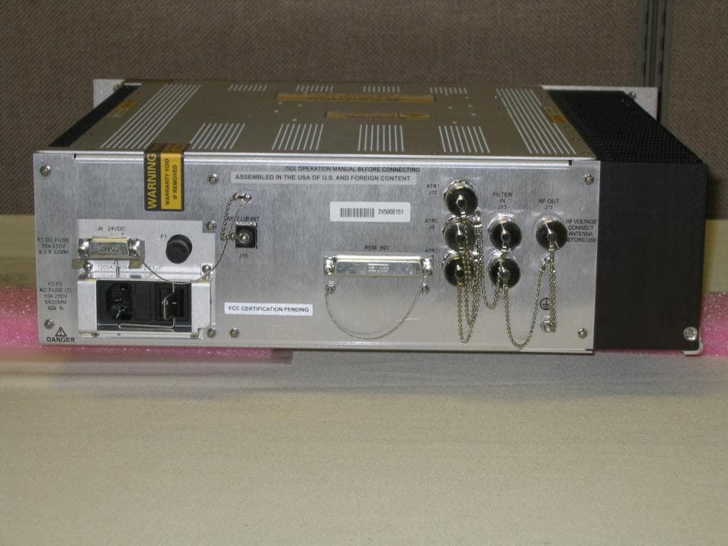
Aug 18, 2013CM-350 (V2) Air Traffic Control VHF Digital Transmitter (VDT)
Equipment Class
TNB - Licensed Non-Broadcast Station Transmitter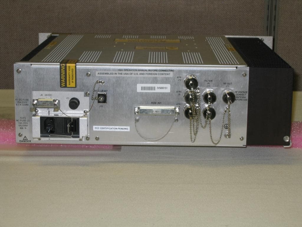
MIJCM300V2
Aug 18, 2013CM-300 (V2) Air Traffic Control VHF Digital Transmitter (VDT)
Equipment Class
TNB - Licensed Non-Broadcast Station Transmitter
MIJPNR-1000
May 08, 2012PathMaker Network Radio
Equipment Class
DTS - Digital Transmission System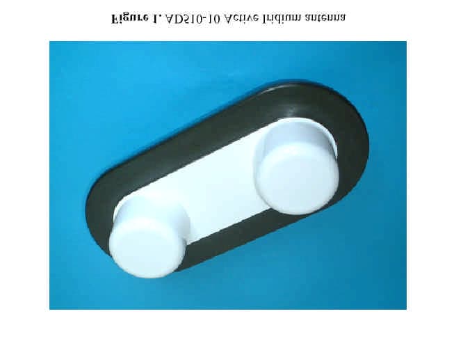
MIJAD510
May 18, 2003Iridium Satellite Transceiver Active Antenna
Equipment Class
AMP - Amplifier
MIJTELCPE-USB-01
Mar 15, 2000Local Multipoint Distribution System
Equipment Class
TNB - Licensed Non-Broadcast Station Transmitter