MIVCDP10EAMEnabler-A CDPD OEM modem
Novatel Wireless Inc.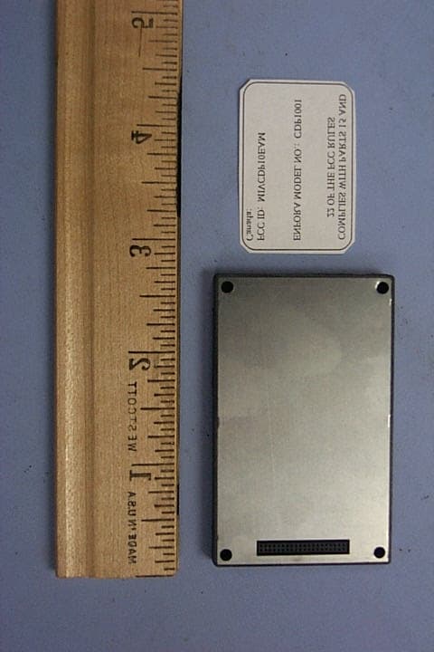
Click to zoom
Application Details
- Equipment Class
- TNB - Licensed Non-Broadcast Station Transmitter
- Date of Grant
- Jan 06, 2002
- Application Purpose
- Original Equipment
- Date of Application
- Oct 18, 2001
- Equipment Note
- Enabler-A CDPD OEM modem
- Frequency Range
- 824.04000000 - 848.97000000
- Company
- Novatel Wireless Inc.
- Country
- Canada
Documents & Files
Document Text
Text extracted from the exhibit documents filed with the FCC. Open a document above to read the original.
Users Manual
FCC REGULATORY COMPLIANCE INTEGRATION AND USE INFORMATION INTEGRATION CONSIDERATIONS AND INSTALLATION REQUIREMENTS The Enabler-G OEM GPRS modem is designed for use in a variety of host units, "enabling" the host platform to perform wireless data communications. However, there are certain criteria relative to integrating the modem into a host platform such as a PC, laptop, handheld or PocketPC, monitor and control unit, etc. that must be considered to ensure continued compliance with FCC compliance requirements. The modem was tested and certified to meet FCC Parts 15 and 24 in a stand-alone configuration, demonstrating that the Enabler-G complies with Part 15 emission limits regardless of the device into which it may be installed. Further, to provide relief in certain applications for the host integrator, the Enabler-G was approved under the "modular approval" process for a transmitter. This approach, described by FCC Public Notice DA 00-131407 released June 26, 2000, is intended to afford relief to equipment manufacturers by eliminating the requirement for obtaining a new equipment authorization for the same transmitter when installed in a new device. However, the host platform integrator must follow all installation instructions and cautionary information necessary to comply with FCC RF exposure requirements. In order to use the Enabler-G without additional FCC certification approvals, the installation must meet the following conditions. Otherwise, additional FCC approvals must be obtained. 1. Fixed and “mobile” applications: At least 20 cm (7.9 in.) separation distance between the antenna and the user’s body must be maintained at all times. For the transmitter to meet the MPE categorical exclusion requirements of 2.1091, the ERP must be less than 1.5 watts for personnel separation distance of at least 20 cm (7.9 in). The maximum antenna gain cannot exceed +3.3dBi. If greater than 1.5 watts exists, then additional testing and FCC approval is required (e.g., see 3 below). 2. If used with a desktop or other application where the antenna can be easily relocated to meet the 20 cm criteria, then this is considered a “mobile” application. If used in a "mobile" application where the antenna is normally separated at least 20 cm (7.9 in) from the human body during device operation, then an appropriate warning label must be placed on the host unit adjacent to the antenna. The label should contain a statement such as the following: WARNING RF exposure. Keep at least 20 cm (7.9 in) separation distance from the antenna and the human body. 3. “Portable” applications: If used in a "portable" application such as a handheld device with the antenna less than 20 cm (7.9 in.) from the human body when the device is operating, then the integrator is responsible for passing additional "as installed" testing. Separate FCC approval for RF exposure compliance is required for end products that do not met the separation or maximum antenna gain criteria. a. SAR (Specific Absorption Rate) testing, with results submitted to the FCC for approval prior to selling the integrated unit. If unable to meet SAR requirements, then the host unit must be restricted to "mobile" use (see 3 below). b. Unintentional emissions, FCC Part 15; results do not have to be submitted to the FCC unless requested, although the test provides substantiation for required labeling (see 5 below). 4. Host unit user manuals and other documentation must also include appropriate caution and warning statements and information. 5. If the FCC ID for the modem is not visible when installed in the host platform, then a permanently attached or marked label must be displayed on the host unit referring to the enclosed modem. For example, the label should contain wording such as: Contains CDPD modem transmitter module FCC ID: MIVGSM0103 This device complies with Part 15 of the FCC Rules. Operation is subject to the following two conditions: (1) This device may not cause harmful interference, and (2) This device must accept any interference received, including interference that may cause undesired operation. or Contains FCC ID: MIVGSM0103 This device complies with Part 15 of the FCC Rules. Operation is subject to the following two conditions: (1) This device may not cause harmful interference, and (2) This device must accept any interference received, including interference that may cause undesired operation. 6. Any antenna used with the modem must be approved by the FCC as either a Class II Permissive Change (including MPEL or SAR data as applicable). The "professional installation" provision of FCC Part 15.203 does not apply. 7. The transmitter and antenna must not be co-located or operating in conjunction with any other antenna or transmitter. Violation of this would allow a user to plug another transmitter in to the product and potentially create an RF exposure condition. WARNING The transmitter and antenna must not be co- located or operating in conjunction with any other antenna or transmitter. Failure to observe this warning could produce an RF exposure condition.
Attestation Statements
661 East 18 th Street Plano, Texas 75074-5601 972-633-4400 Tel 972-633-4444 Fax www.nextcell.com October 18, 2001 Federal Communications Commission 7435 Oakland Mills Road Columbia, MD 21046 USA SUBJECT:FCC ID MIVCDP10EAM APPLICATION FOR MODULAR APPROVAL REFERENCE:(a)FCC Public Notice DA 00-1407, released June 26, 2000 ATTACHMENT:(1)User Manual Section, FCC REGULATORY COMPLIANCE INTEGRATION AND USE INFORMATION, INTEGRATION CONSIDERATIONS AND INSTALLATION REQUIREMENTS Enfora, Inc. recently developed a new, small form-factor (size) wireless CDPD data modem as an OEM (internally installed, not readily removable)) device to be used in a variety of applications. In accordance with page 2 of Public Notice DA 00--1407, please find responses to the eight items listed: 1."The modular transmitter must have its own RF shielding. ..." The Enfora modem, unofficially called the Enabler-A at this time, incorporates RF shielding and has successfully passed Part 15 emissions testing in the stand-alone configuration. 2."The modular transmitter must have buffered modulation/data inputs ... to ensure that it wil comply with Part 15 requirements ... " The Enabler-A successfully passed Part 15 tests in the stand- alone configuration. 3."The modular transmitter must have its own power supply regulation. ..." the Enabler-A complies, as verified by successful completion of Part 15 testing in the stand-=alone configuration. 4."The modular antenna must comply with antenna requirements .." The Enabler-A User Manual contains a section specifically addressing the requirements of this item, as shown in the excerpt provided as Attachment (1). 5."The modular transmitter must be tested in the stand-alone configuration ..."the Enabler-A was in the stand-alone configuration for Parts 15 and 22 testing. 6."The FCC transmitter must be labeled with its own FCC ID number, ... if .. not visible ..." As shown in the excerpt from the User's manual, Attachment (1), Enfora complkies with this requirement. 7."The modular antenna must comply with any specific rule or operating requirements applicable to the transmitter and the manufacturer must provide adequate instructions along with the module to explain any such requirements. .." The Enabler-A User Manual, and other exhibits provided with the application address this requirement. 8.The modular transmitter must comply with any applicable RF exposure requirements ..." Enfora has attempted to address all conceivable applications of the OEM modem, including portable and mobile 661 East 18 th Street Plano, Texas 75074-5601 972-633-4400 Tel 972-633-4444 Fax www.nextcell.com as well as stationary applications. Attachment (1) contains paragraphs addressing various RF exposure conditions and methods of risk mitigation. In summary, Enfora, inc. has made a good faith attempt to ensure that all applicable FCC requirements were met for the new form factor OEM CDPD modem. If you have questions or need additional information, please contact the undersigned. Sincerely, Durward E. Rutledge, P.E. Vice President Product Integrity 972-437-3342 Applicant: Enfora, Inc. 661 East 18 th Street Plano, Texas 75074-5601
Block Diagram
LNA Mixer Downconverter FM / IF Limiter / Detector Mixer PA I/Q Modulator Power Cntrl SAW Duplexer Rx Ant Tx Pout = + 28 dBm max Pout = + 0 dBm min Pin = - 111 dBm min Pin = - 51 dBm max Dual PLL/ VCO I Lowpass Filter Q Lowpass Filter 0 90 60KHz Active Filter RC Filter Compar- ators Enabler-A Functional Block Diagram DC Amp Main LO Freq 914.04-938.97 MHz 60KHz Active Filter Detect Lim IF Splitter Buffer Amp TXLO Freq 90 MHz TX Carrier Freq 824.04- 848.97 MHz Amp 15.36 MHz VTCXO I Q FPGA Microprocessor AVR Serial Interface 40 pin Connector PLL/VCO RXLO Freq 89.88 MHz Vcntrl From AVR Transceiver Control & Monitoring RSSI to FPGA External Power 3.15-4.2 VDC Digital LDO Power Management TX LDO TCVCXO LDO Xilinx LDO Memory file: Enabler-A.vsd, REV. 8/14/01 Temp Sense To Monitor Intfc. EEProm / 2 RX LDO DRAM 2MB Flash 1MB 45MHz IF RX Freq 869.04- 893.97 MHz
Cover Letter(s)
661 East 18 th Street Plano, Texas 75074-5601 972-633-4400 Tel 972-633-4444 Fax www.nextcell.com Federal Communications Commission 7435 Oakland Mills Road Columbia, MD 21046 USA Authority to Act as Agent to the Federal Communications Commission On our behalf, I appoint Nemko Dallas, Inc. to act as agent in the preparation of this application for equipment authorization to the Federal Communications Commission. I certify that submitted Exhibits properly describe the device or system for which equipment authorization is sought. I also certify that each unit manufactured, imported or marketed, as defined in the Commission's regulations will have affixed to it a label identical to that submitted for approval with this application. APPLICANT ANTI-DRUG ABUSE CERTIFICATION: In signing this letter, Applicant certifies that, in the case of an individual applicant, he or she is not subject to a denial of federal benefits, that includes FCC benefits, pursuant to Section 5301 of the Anti-Drug Abuse Act of 1988, 21 U.S.C. 853(a), or, in the case of a non-individual applicant (e.g. corporation, partnership or other unincorporated association), no party to the application is subject to a denial of federal benefits, that includes FCC benefits, pursuant to that section. For the definition of a "party" for these purposes, see 47 CFR 1.2002(b). Dated this 13th Day of August 2001 Agency agreement expiration date: By: Durward E. Rutledge, P.E. Title: Vice President Product Integrity Telephone: 972-437-3342 Applicant: Enfora, Inc. 661 East 18 th Street Plano, Texas 75074-5601
Cover Letter(s)
661 E. 18 th Street Plano, Texas 75074-5601 REQUEST FOR CONFIDENTIALITY Enfora, Inc. hereby requests confidentiality with regard to the following documents in the filing for equipment approval identified by FCC ID. No. MIVCDP10EAM. (1) (1) Schematic diagrams contained in electronic files identified below. • • CDP10D01MG002SCH It is the opinion of Enfora, Inc. that disclosure of this information would result in significant loss of revenue. This information should be kept confidential for 3 years. Durward E. Rutledge, P.E. Durward E. Rutledge, P.E. Vice President of Product Integrity Enfora, Inc. 661 E. 18 th Street Plano, Texas 75074-5601
ID Label/Location Info
COMPLIES WITH PARTS 15 AND 22 OF THE FCC RULES ENFORA MODEL NO.: CDP10EA FCC ID: MIVCDP10EAM Canada: ENFORA Enabler-A MODEL NO.: CDP10EAEID NO.: XX XX XX XX XX XX FCC ID:MIVCDP10EAMCanada:XXXXXXX This device has been tested and found to comply with Part 15 and Part 22 of FCC Rules. Operation is subject to the following conditions: (1) This device must not cause harmful interference; (2) This device must accept any interference received, including interference that may cause undesired operation; and (3) FCC guidelines stipulate that the antenna should be more than 20 cm (7 .9in.) from the body.
Operational Description
Functional Description For Enfora Enabler-A CDPD Modem Enfora, Inc. 661 E. 18th Plano, TX 75074 WARNING: This document contains proprietary information and must not be reproduced without the prior written consent of Enfora, Inc. Table Of Contents 1. CDPD BACKGROUND....................................................................................................................... 3 2. THEORY OF OPERATION............................................................................................................... 3 2.1 I NTRODUCTION ................................................................................................................................3 2.2 A BBREVIATIONS .............................................................................................................................. 4 2.3 F REQUENCY A LLOCATION (M-ES).................................................................................................. 4 2.3.1 Power control ......................................................................................................................... 5 2.4 D IGITAL S ECTION ............................................................................................................................ 6 2.4.1 Processor and Memory...........................................................................................................6 2.4.2 I&Q Generation and Transmission Control ........................................................................... 6 2.4.3 ADC – System and Data ......................................................................................................... 6 2.4.4 Serial Interface ....................................................................................................................... 7 2.4.5 FPGA Functions ..................................................................................................................... 7 2.4.6 RF interface and Frequency Generation ................................................................................ 7 2.5 R ECEIVER S ECTION ......................................................................................................................... 8 2.5.1 Duplexer ................................................................................................................................. 8 2.5.2 LNA and First Conversion ...................................................................................................... 8 2.5.3 First IF Stage.......................................................................................................................... 8 2.5.4 Second Conversion, Limiter and IF filtering .......................................................................... 8 2.6 T RANSMIT P ATH .............................................................................................................................. 9 1. CDPD Background The Cellular Digital Packet Data (CDPD) network is a two-way wireless data communication system. This system uses cellular telephone channels to transfer data seamlessly from a mobile end system. CDPD operates within the already existing cellular telephone infrastructure utilizing the idle time that exist on cellular voice channels to send small packets of data, called datagrams, to a designated receiver. Researchers estimate that over 30% of a cellular channel’s airtime is idle, even during heavy traffic. The CDPD system sends down the various cellular channels to locate an open channel. This process is called “sniffing.” Once the CDPD system has located an open channel, the modem begins to send datagrams over the channel to the designated end user. In order that this process does not interfere with the cellular phone transmission, the CDPD system has regulated channel “hops” to ensure that CDPD usage will not block a cellular voice channel for an extended period of time. Also, if a voice channel is activated, the CDPD system detects this voice message and automatically “hops” to the next available idle channel. This process is quite complex. However, the user need not be aware of this process. The CDPD system manages the routing of the individual data packets to the proper destination. On a basic level, the CDPD network operates like any other computer network with the exception that the CDPD mobile end system is free to roam wirelessly and conduct network operation from other locations using the network of cellular carriers. The CDPD network is made of a series of cellular networks that are operated by various cellular carriers. These carriers provide the user with network management as well as application services. To increase user security carriers use forward error correction, authentication, and encryption. The cellular carrier is responsible for all accounting services for the CDPD service. The user selects the CDPD carrier service with which to operate by registering with an individual carrier. Generally, an area will have two cellular carriers that provide CDPD service. The user may sign up with either of the two carriers. 2. Theory of Operation 2.1 Introduction Enfora’s Enabler-A CDPD M-ES RF circuitry may be divided into 3 major sections namely, 2 independent sections, the RX circuit, and the TX circuit and LO’s in which the RX circuit and TX circuits depend on for proper operation. The RX section uses a dual conversion superheterodyne technology to downconvert the cellular RF channel signal to its 1st IF of 45 MHz and then to the 2nd IF of 60 KHz. IF pre-filtering is performed at 45 MHz but the main IF filtering is performed at 60 KHz inside the Sony CXA1742Q device. For the TX section, the I & Q waveforms from the FPGA output are conditioned and filtered before they are modulated and upconverted to the 836.01 MHz ( + 12.5 MHz) transmit frequency. Mixing 90 MHz with the Main LO derives the TX frequency. The receive channel and transmit channel frequencies are always 45 MHz apart from each other with an alloc…
Text truncated - open the document above for the full version.
Parts List/Tune Up Info
Tuneup Procedure The rf power output is preset during the manufacturing process. The power output is maintained within its operating range via ALC circuit. The transmitter uses a frequency synthesizer thus there are no frequency alignments that must be made.
RF Exposure Info
Prediction of MPE limit at a given distance Equation from page 18 of OET Bulletin 65, Edition 97-01 where:S = power density P = power input to the antenna G = power gain of the antenna in the direction of interest relative to an isotropic radiator R = distance to the center of radiation of the antenna Maximum peak output power at antenna input terminal:28.50(dBm) Maximum peak output power at antenna input terminal:707.9457844(mW) Antenna gain(typical):3.3(dBi) Maximum antenna gain:2.13796209(numeric) Prediction distance:20(cm) Prediction frequency:824(MHz) MPE limit for uncontrolled exposure at prediction frequency:0.533333333(mW/cm^2) Power density at prediction frequency:0.301113(mW/cm^2) Maximum allowable antenna gain:5.782685833(dBi) The maximum allowable antenna gain for this device(assuming 0 dB cable loss) would be 5.8 dBi. This device should be usedonly in devices that can be classified as Mobile(a separation distance of at least 20 cm from nearby persons. 2 4R PG S π =
Test Report
Nemko Test Report:1L0435RUS2 Applicant:Enfora, Inc. 661 East 18 th Street Plano, TX 75074-5601 Equipment Under Test:Enabler-A (E.U.T.) FCC ID:MIVCDP10EAM In Accordance With:FCC Part 22, Subpart H 800 MHz Cellular Subscriber Units Tested By:Nemko Dallas Inc. 802 N. Kealy Lewisville, TX 75057-3136 Authorized By: Tom Tidwell, EMC/Wireless Manager Date:9/10/01 Total Number of Pages:43 Nemko Dallas FCC PART 22, SUBPART H 800 MHz CELLULAR SUBSCRIBER UNITS EQUIPMENT:Enabler-A FCC ID: MIVCDP10EAMPROJECT NO.:1L0435RUS2 Page 2 of 43 Table of Contents Section 1. Summary of Test Results........................................................................................3 Section 2. General Equipment Specification.............................................................................5 Section 3. RF Power Output....................................................................................................8 Section 4. Occupied Bandwidth...............................................................................................9 Section 5. Spurious Emissions at Antenna Terminals.............................................................14 Section 6. Field Strength of Spurious.....................................................................................24 Section 7. Frequency Stability...............................................................................................27 Section 8. Test Equipment List..............................................................................................29 ANNEX A - TEST DETAILS..................................................................................................30 ANNEX B - TEST DIAGRAMS..............................................................................................40 Nemko Dallas FCC PART 22, SUBPART H 800 MHz CELLULAR SUBSCRIBER UNITS EQUIPMENT:Enabler-A FCC ID: MIVCDP10EAMPROJECT NO.:1L0435RUS2 Page 3 of 43 Section 1.Summary of Test Results Manufacturer:Enfora Model No.:Enabler-A Serial No.:None General:All measurements are traceable to national standards. These tests were conducted on a sample of the equipment for the purpose of demonstrating compliance with FCC Part 22, Subpart H. New SubmissionProduction Unit Class II Permissive ChangePre-Production Unit THIS TEST REPORT RELATES ONLY TO THE ITEM(S) TESTED. THE FOLLOWING DEVIATIONS FROM, ADDITIONS TO, OR EXCLUSIONS FROM THE TEST SPECIFICATIONS HAVE BEEN MADE. See “ Summary of Test Data”. NVLAP LAB CODE: 100426-0 Nemko Dallas Inc. authorizes the above named company to reproduce this report provided it is reproduced in its entirety and for use by the company’s employees only. Any use which a third party makes of this report, or any reliance on or decisions to be made based on it, are the responsibility of such third parties. Nemko Dallas Inc. accepts no responsibility for damages, if any, suffered by any third party as a result of decisions made or actions based on this report. This report applies only to the items tested. Nemko Dallas FCC PART 22, SUBPART H 800 MHz CELLULAR SUBSCRIBER UNITS EQUIPMENT:Enabler-A FCC ID: MIVCDP10EAMPROJECT NO.:1L0435RUS2 Page 4 of 43 Summary Of Test Data NAME OF TESTPARA. NO. SPEC.RESULT RF Power Output2.10467W ERPComplies Audio Frequency Response2.10476dB/OctaveN/A Audio Low Pass Filter Response2.1047GraphN/A Modulation Limiting2.1047GraphN/A Occupied Bandwidth (Voice & SAT)2.1049MaskN/A Occupies Bandwidth (WB Data & SAT) 2.1049MaskN/A Occupied Bandwidth (ST)2.1049MaskComplies Occupied Bandwidth (SAT)2.1049MaskN/A Occupied Bandwidth (SAT)2.1049Not SpecifiedN/A Spurious Emissions at Antenna Terminals 2.1051-13 dBmComplies Field Strength of Spurious Emissions2.1053 82.3 dBμV/m Complies Frequency Stability2.10552.5 ppmComplies This transmitter does not support analogue voice modulation. . Nemko Dallas FCC PART 22, SUBPART H 800 MHz CELLULAR SUBSCRIBER UNITS EQUIPMENT:Enabler-A FCC ID: MIVCDP10EAMPROJECT NO.:1L0435RUS2 Page 5 of 43 Section 2.General Equipment Specification Frequency Range: 824.04 MHz to 848.97 MHz Tunable Bands: 824.04 MHz to 848.97 MHz Necessary Bandwidth: 30 kHz Type of Modulation and Designator: DXW Output Impedance: 50 ohms RF Power Output (rated): 700 mW Number of Channels: 832 Duty Cycle: Continuous Channel Spacing: 30 kHz Operator Selection of Frequency: Software Controlled Power Output Adjustment Capability: Software Controlled Nemko Dallas FCC PART 22, SUBPART H 800 MHz CELLULAR SUBSCRIBER UNITS EQUIPMENT:Enabler-A FCC ID: MIVCDP10EAMPROJECT NO.:1L0435RUS2 Page 6 of 43 Description of Modifications For Class II Permissive Change Modifications Made During Testing Nemko Dallas FCC PART 22, SUBPART H 800 MHz CELLULAR SUBSCRIBER UNITS EQUIPMENT:Enabler-A FCC ID: MIVCDP10EAMPROJECT NO.:1L0435RUS2 Page 7 of 43 Operational Description The Enabler_A CDPD modem is a full duplex wireless modem for embedded applications. The host supplies DC power and the antenna. The modem provides wide area access using the AMPS frequency band. The modulation used is a 0.5 GMSK format. System Diagram Panasonic "Toughbook" Laptop Nemko Dallas FCC PART 22, SUBPART H 800 MHz CELLULAR SUBSCRIBER UNITS EQUIPMENT:Enabler-A FCC ID: MIVCDP10EAMPROJECT NO.:1L0435RUS2 Page 8 of 43 Section 3.RF Power Output NAME OF TEST: RF Power OutputPARA. NO.: 2.1046 TESTED BY: David LightDATE: 8/9/2001 Test Results:Complies. Measurement Data: ChannelPower at Antenna Terminal (dBm) Antenna Gain (dBi) Output Power (EIRP) (dBm) 99128.5028.5 36728.0028.0 79927.6027.6 Note – The device was tested at Nominal voltage (115 Vac), 98 Vac and 132 Vac (+/- 15%) with no change in output power. The AC adapter supplied with the host operates from 100-240 Vac. Equipment Used: 1029-1030-1474-1082 Measurement Uncertainty: +/- 0.6dB Temperature: 22 °C Relative Humidity: 50% Nemko Dallas FCC PART 22, SUBPART H 800 MHz CELLULAR SUBSCRIBER UNITS EQUIPMENT:Enabler-A FCC ID: MIVCDP10EAMPROJECT NO.:1L0435RUS2 Page 9 of 43 Section 4.Occupied Bandwidth NAME OF TEST: Occupi…
Text truncated - open the document above for the full version.
Contact Information
Applicant
Todd Gallagher(Manager, Regulatory Engineering)
Technical Contact
Nemko Dallas, Inc.Tom Tidwell
[email protected]972-436-9600
802 N. Kealy · Lewisville, Texas · United States
Non-Technical Contact
Nemko Dallas, Inc.Davida Hanson
[email protected]972-436-9600
Test Firm
Nemko Dallas, Inc.Michael Cantwell
Technical Specifications
| # | Rule Parts | Frequency Range | Power Output | Emission | Tolerance |
|---|---|---|---|---|---|
| 1 | 22.901(d) | 824.04 MHz - 848.97 MHz | 700.00 mW | 30K0DXW | 203.0000000000 Hz |
Other Applications from Novatel Wireless Inc.
MIVRTT2211
Jan 22, 2013CDMA Licensed Transmitter
Equipment Class
PCB - PCS Licensed Transmitter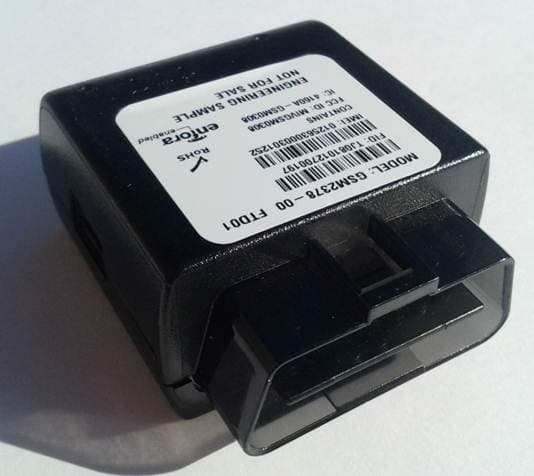
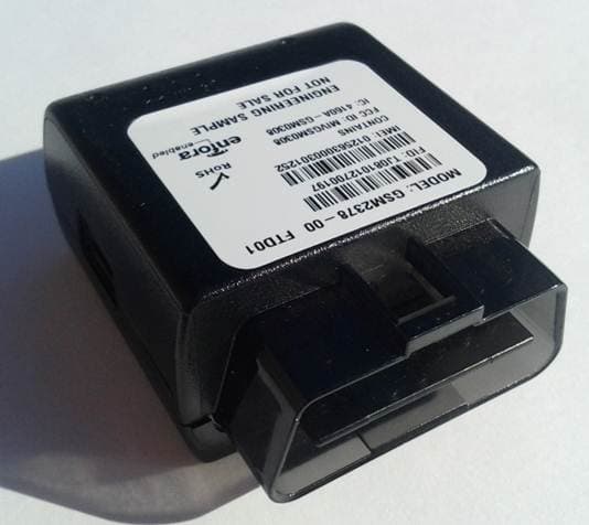
MIVGSM2378
Dec 23, 2012PCS GSM/ GPRS Licensed Transmitter
Equipment Class
PCB - PCS Licensed Transmitter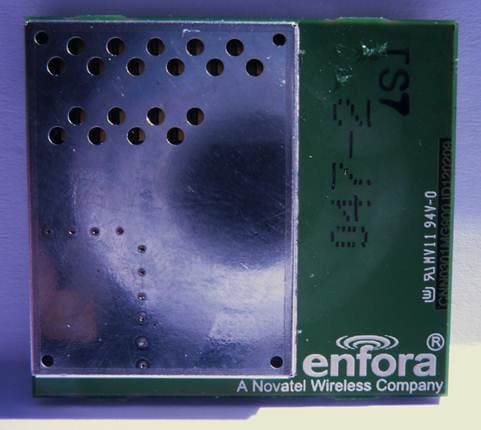
MIVCNN0301
May 10, 20121XRTT Multi-Band M2M OEM Module
Equipment Class
PCB - PCS Licensed Transmitter
MIVGSM2428
Jun 15, 2011GSM/ GPRS Personal Tracker
Equipment Class
JBP - Part 15 Class B Computing Device Peripheral
MIVGSM5218
Mar 15, 2011GSM/GPRS Asset Tracker
Equipment Class
PCB - PCS Licensed Transmitter