MIVEDG0200Wireless Edge Modem
Novatel Wireless Inc.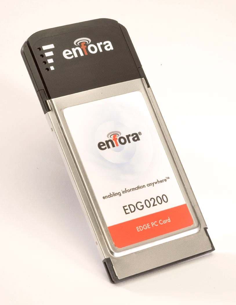
Click to zoom
Application Details
- Equipment Class
- PCB - PCS Licensed Transmitter
- Date of Grant
- Nov 03, 2005
- Application Purpose
- Original Equipment
- Date of Application
- Nov 03, 2005
- Equipment Note
- Wireless Edge Modem
- Frequency Range
- 824.20000000 - 848.80000000
- Company
- Novatel Wireless Inc.
- Country
- Canada
Documents & Files
Document Text
Text extracted from the exhibit documents filed with the FCC. Open a document above to read the original.
Users Manual
Enfora® EDG0200 PCMCIA EDGE Card User Manual Version 1.0 Enfora L.P. 661 E. 18 th Street Plano Texas 75074 www.enfora.com User Manual: EDG0200MAN001 GPRS/EDGE PCMCIA Card Users’ Manual Page ii Copyright 2005, Enfora L.P. Version: 1.0 Date: 9/15/05 Status: Draft Document Control ID: EDG0200MAN001 Copyright Statement Copyright 2004 by Enfora L.P. All rights reserved. No portion of this document may be copied, photocopied, reproduced, transmitted, transcribed, stored in a retrieval system or translated into any language or computer language, in any form or by any means, electronic, mechanical, magnetic, optical, chemical, manual or otherwise, without the prior written permission of Enfora L.P. © 2005 Enfora, L.P. All rights reserved. Disclaimer Enfora L.P. makes no representations or warranties, either expressed or implied, with respect to the contents hereof and specifically disclaims any warranties, merchantability or fitness for any particular purpose. Further, Enfora L.P. reserves the right to revise this publication, and to make changes from time to time in the contents hereof without obligation of Enfora L.P. to notify any person of such revision or changes. ALL INFORMATION IS PROVIDED BY ENFORA L.P. ON AN “AS IS” BASIS ONLY. THIS COMPANY PROVIDES NO REPRESENTATIONS AND WARRANTIES, EXPRESS OR IMPLIED, INCLUDING THE IMPLIED WARRANTIES OF FITNESS FOR A PARTICULAR PORPOSE, MERCHANTABILITY AND NONINFRINGEMENT. All product names mentioned within this document are the trademark of their respective owners. Enfora, LP. Proprietary Information EDG0200MAN001 Adobe® Acrobat Reader, © 1987-1999 Adobe Systems Inc. All rights reserved. Adobe and Acrobat are trademarks of Adobe Systems Inc. GPRS/EDGE PCMCIA Card Users’ Manual Page iii Copyright 2005, Enfora L.P. Safety Information for Wireless Handheld Devices FCC RF EXPOSURE INFORMATION WARNING! Read this information before using your wireless device. In August 1986 the Federal Communications Commission (FCC) of the United States with its action in Report and Order FCC 96-326 adopted an updated safety standard for human exposure to radio frequency (RF) electromagnetic energy emitted by FCC regulated transmitters. Those guidelines are consistent with the safety standard previously set by both U.S. and international standards bodies. The design of this phone/device complies with the FCC guidelines and these international standards. Use only the supplied or approved antenna. Unauthorized antenna modifications, or attachments could impair call quality, damage the phone, or result in violation of FCC regulations. Do not use the phone with a damaged antenna. Please contact your local dealer for replacement antenna. For more information about RF exposure, please visit the FCC website at www.fcc.gov The equipment certifications appropriate to your device are marked on the device and product specific information. The use of the equipment is subject to the following conditions: FCC COMPLIANCE STATEMENT This device complies with Part 15b of the FCC Rules. Operation is subject to the following two conditions: (1) This device may not cause harmful interference, and (2) this device must accept any interference received, including interference that may cause undesired operation. CAUTION Changes or modifications without the express consent of Enfora, L.P. voids the user’s authority to use the equipment and will avoid any applicable warranty. This equipment has been tested and found to comply with the limits pursuant to Part 15 Subpart B , Part 22 and Part 24 of the FCC rules. These limits are designed to provide reasonable protection against harmful interference in an appropriate installation. This equipment generates, uses, and can radiate radio frequency energy and, if not used in accordance with instructions, can cause harmful radiation to radio communication. However, there is no guarantee that interference will not occur in a particular installation. If the equipment does cause harmful interference in radio and television reception, which can be determined by turning the equipment on and off, the user is encouraged to try to correct the interference by one or more of the following measures: Reorient or relocate the receiving antenna Increase the separation distance between the equipment and the receiver Contact Enfora, L.P. Technical Support for assistance. GPRS/EDGE PCMCIA Card Users’ Manual Page iv Copyright 2005, Enfora L.P. Safety Instructions • Use of radio equipment is prohibited in hospitals and may interfere with the use of medical equipment. Do NOT use the EDG0200 Card in hospitals. • FCC regulations prohibit using your wireless device during any air flight. Switch OFF your PCMCIA EDGE Card prior to flight and in accordance with the airline’s acceptable devices policy. • DO NOT use the EDG0200 Card in the vicinity of explosive atmospheres. Turn your EDG0200 Card OFF in a “Blasting Area” or gas station. Obey all signs and instructions • Local laws may prohibit the use of this device while driving in order to avoid distractions and prevent accidents. DO NOT use the EDG0200 Card while driving, in order to avoid distractions and prevent accidents. If the equipment must be used, use with only approved hands-free accessories. • The Health Industry Manufactures Association recommends that a minimum separation of six (6”) inches be maintained between a handheld wireless device and a pacemaker to avoid potential interference with the pacemaker. Operating Instructions Never violate any of the following Rules and Regulations of the FCC when using your wireless device. Such violations are punishable by fine, imprisonment, or both. • Never use obscene, indecent, or profane language. • Never use our EDG0200 Card to send false distress calls. • Never wiretap or otherwise intercept a device call, unless you have first obtained the consent of the parties participating in the call. • Never make any anonymous calls to annoy, harass or molest other people. • Never charg…
Text truncated - open the document above for the full version.
Cover Letter(s)
® Enfora, L.P. 661 E. 18 th Street Plano, TX 75074-5601 (972) 633-4400 Fax (972) 633-4444 September 14, 2005 REQUEST FOR CONFIDENTIALITY Enfora, L.P., requests confidentiality with regard to the following documents in the filing for equipment approval identified by FCC ID MIVEDG0200, Enfora PN EDG0200. (1) Schematic diagrams contained in electronic file EDG0200SCH_RevA.PDF. (2) Block diagram located in electronic file EDG0200.BlockDiagram1.Confidential.PDF. It is the opinion of Enfora, L.P., disclosure of this information would result in significant loss of revenue. These documents are also covered under multiple patents and non-disclosure agreements with other companies. This information should be kept confidential for 5 years. Scott Yarberry AVP, Product Development Enfora, L.P. 661 E. 18 th St Plano, TX 75074 972-633-4400
Cover Letter(s)
Enfora, L.P. 661 E. 18 th St. Plano, TX 75074-5601 972.633.4400 September 15, 2005 Federal Communications Commission 445 12 th Street SW Washington, DC 20554 Subject: Limited Agency Agreement Re: Enfora, L.P., EDG0200 Module We, Enfora, L.P., hereby authorized Intertek Testing Services to act as our agent for the purpose of preparing application for FCC ID number MIVEDG0200 under all applicable parts of the FCC rules and regulations. The effective date of this limited agency agreement is September 15, 2005. The limited agency agreement expires on September 15, 2006 unless sooner terminated or extended by written notice to Intertek Testing Services and the Federal Communications Commission. This is to advise that we are in full compliance with the Anti-Drug Abuse Act. The applicant is not subject to a denial of federal benefits pursuant to Section 5301 of the Anti-Drug Act of 1988, 21 U.S.C. 862, and no party to the application is subject to a denial of federal benefits pursuant to that section. If you have any questions or comments, please do not hesitate to contact me. Sincerely, John H. Denton
ID Label/Location Info
EDG0200 EDGE PC Card Quad Band 850/900/1800/1900 MHz GSM / GPRS MSC-10 / EDGE MSC-10 41 mm 6 5 m m 41 mm 2 6 m m 2 0 m m EDG0200 Label Detail enabling information anywhere TM BAR CODEIMEI FCC ID: MIVEDG0200IC: 4160A-EDG0200SIM
Internal Photos
FCC ID: MIVEDG0200 FCC ID: MIVEDG0200 FCC ID: MIVEDG0200
Operational Description
® EDG0200 Operational Description Enfora, L.P. 661 E. 18 th Street Plano, TX 75074-5601 (972) 633-4400 Fax (972) 633-4444 The information contained in this document is proprietary to Enfora, L.P. and may not be disclosed or transferred to anyone without the expressed written consent of Enfora, L.P. Information in this document is covered under multiple party Non-Disclosure Agreements and patents. Page 1 of 2 General Description The EDG0200 PC Card is a quad-band (GSM, EGSM, DCS, PCS) wireless modem that is capable of operating in GSM, GPRS, and EGPRS modes. The card utilizes a Silicon Laboratories Si4210 Transceiver. This transceiver is highly integrated and provides virtually all radio functions. An RFMD 2705 handles the 8-PSK modulation in the EGPRS mode. Circuitry & Devices Provided for Determining & Stabilizing Frequency System Reference Clock: The transceiver uses a 26 MHz Digitally Controlled Crystal Oscillator (DCXO) to generate a precise system reference clock. Any initial offset error in the external crystal can be calibrated during factory test if needed. This clock is initially accurate to within 5.7 ppm. After attaching to the network, the clock is within 0.1 ppm. Frequency Synthesizer: The frequency synthesizer uses an integrated RF VCO, Varactor, and loop filter. The IF & RF output frequencies are controlled via software. The RF VCO is used in both transmit and receive modes. Transmitter: The transmit section can operate in GMSK and 8-PSK modulation modes. In GMSK mode, the baseband I/Q signals modulate the OPPL (offset phase-locked loop). The power amplifier operates in a saturated non-linear mode and the baseband ramp signal is applied directly to the power amplifier. In 8-PSK mode, the OPLL is un-modulated and held in a CW (carrier wave) mode to act as a local oscillator that up-converts the baseband I/Q signal. The power amplifier operates in a constant gain linear mode and the baseband ramp signal is applied to the VGA (variable gain amplifier. Circuitry & Devices Provided for Suppression of Spurious Radiation In GMSK mode, low-pass filters before the OPLL phase detector reduce the harmonic content of the Quadrature Modulator and feedback mixer outputs. In 8-PSK mode, the low bands (850 & 900 MHz) have a band-pass filter incorporated between the modulator and the PA. In both modes, low-pass filters are integrated into the RF switch (RFS). ® EDG0200 Operational Description Enfora, L.P. 661 E. 18 th Street Plano, TX 75074-5601 (972) 633-4400 Fax (972) 633-4444 The information contained in this document is proprietary to Enfora, L.P. and may not be disclosed or transferred to anyone without the expressed written consent of Enfora, L.P. Information in this document is covered under multiple party Non-Disclosure Agreements and patents. Page 2 of 2 Circuitry & Devices Provided for Limiting Modulation All modulation waveforms are generated/controlled by the DSP in the Analog Baseband integrated circuit. Circuitry & Devices Provided for Limiting Power The RF Power Amplifier’s output level is controlled from an analog voltage generated by the Analog Baseband integrated circuit. In GMSK mode, the Power Amplifier provides an integrated power control loop that maintains the desired power output level. In 8-PSK mode, the Power Amplifier is in a constant gain mode and power is controlled via a power control loop in the 2705 modulator.
Parts List/Tune Up Info
® Enfora, L.P. 661 E. 18 th Street Plano, TX 75074-5601 (972) 633-4400 Fax (972) 633-4444 September 14, 2005 Tune-Up Procedure Description for EDG0200 Power Adjustments The RF power output of the modem is preset during the manufacturing process via software- controlled adjustment of calibration parameters referenced to a base-station simulator. In normal operation, the RF output power is maintained via an ALC circuit. The end-user does not have access to the calibration/power adjustment of the device. Frequency Adjustments The transceiver uses a frequency synthesizer that is synchronized to the cell phone system’s base-station clock. No frequency alignments are needed. Scott Yarberry AVP, Product Development Enfora, L.P. 661 E. 18 th St Plano, TX 75074 972-633-4400
RF Exposure Info
This report is for the exclusive use of Intertek's Client and is provided pursuant to the agreement between Intertek and its Client. Intertek's responsibility and liability are limited to the terms and conditions of the agreement. Intertek assumes no liability to any party, other than to the Client in accordance with the agreement, for any loss, expense or damage occasioned by the use of this report. Only the Client is authorized to copy or distribute this report and then only in its entirety. Any use of the Intertek name or one of its marks for the sale or advertisement of the tested material, product or service must first be approved in writing by Intertek. The observations and test results in this report are relevant only to the sample tested. This report by itself does not imply that the material, product, or service is or has ever been under an Intertek certification program. SAR TEST REPORT Project Number: 3081013 8/17/2005 Evaluation of the Edge PC Card Model Number: EDG0200 FCC ID: MIVEDG0200 FCC Part 2.1093 For Enfora Test Performed by: Test Authorized by: Intertek 731 Enterprise Drive Lexington, KY 40510 Enfora 661 E. 18th Street Plano, TX 75074 Prepared By:_______________________________Date:____ 8/17/2005________ Jason Centers, Senior Project Engineer Approved By:_______________________________Date:____ 8/17/2005_______ Bryan C. Taylor, EMC Team Leader Intertek 731 Enterprise Drive, Lexington, KY 40510 Telephone: 859-226-1000 Fax: 859-226-1040 Web: www.etlsemko.com 731 Enterprise Drive, Lexington KY 40510 Evaluation For:Enfora FCC ID: MIVEDG0200 Model No: EDG0200 Project Number: 3081013 Page 2 of 21 FCC Part 2.1093 TABLE OF CONTENTS 1 INTRODUCTION ...............................................................................................................................................3 2 JOB DESCRIPTION...........................................................................................................................................4 2.1 CLIENT INFORMATION....................................................................................................................................4 2.2 TEST PLAN REFERENCE: ..................................................................................................................................4 2.3 EQUIPMENT UNDER TEST (EUT) ....................................................................................................................5 2.3.1 System Support Equipment ....................................................................................................................6 2.3.2 Cables associated with EUT ..................................................................................................................6 2.3.3 System Block Diagram...........................................................................................................................6 2.3.4 Justification............................................................................................................................................7 2.3.5 Mode(s) of operation .............................................................................................................................7 2.4 MODIFICATIONS REQUIRED FOR COMPLIANCE................................................................................................7 2.5 RELATED SUBMITTAL(S) GRANTS..................................................................................................................7 2.6 TEST SITE DESCRIPTION.................................................................................................................................8 2.7 MEASUREMENT UNCERTAINTY......................................................................................................................9 2.8 MEASUREMENT TRACTABILITY....................................................................................................................10 3 SPECIFIC ABSORBTION RATE ...................................................................................................................11 3.1 TEST LIMITS.................................................................................................................................................11 3.2 TEST EQUIPMENT.........................................................................................................................................12 3.3 TISSUE SIMULATING LIQUID DESCRIPTION AND VALIDATION......................................................................13 3.4 DIPOLE SYSTEM VALIDATION......................................................................................................................14 3.4.1 Test Procedure.....................................................................................................................................16 3.4.2 Conducted Output Power: ...................................................................................................................16 3.4.3 Test Positions: .....................................................................................................................................16 3.4.4 Reference Power Measurement: ..........................................................................................................16 3.4.5 Coarse Scan:........................................................................................................................................16 3.4.6 Zoom Scan: ..........................................................................................................................................16 3.4.7 Data Extrapolation: .............................................................................................................................16 3.4.8 Reference Power Measurement: ..........................................................................................................16 3.4.9 RF Ambient Activity:...........................................................…
Text truncated - open the document above for the full version.
Test Report
TEST REPORT Report Number: 3081013DAL-001 Project Number: 3081013 Evaluation of the Wireless MODEM Model Number: EDG0200 FCC ID: MIVEDG0200 FCC Part 2 FCC Part 15 FCC Part 22 Subpart H FCC Part 24 Subpart E For Enfora Test Performed by: Test Authorized by: Intertek 420 N Dorothy Drive Richardson, TX 75081 Enfora 661 E. 18 th Street Plano, TX 75074 Prepared By:_______________________________Date:___ 9-16-05 ___ Sudesh Kamble, EMC Team Leader Approved By:______________________________Date:__9-16-05 _____ This report is for the exclusive use of Intertek's Client and is provided pursuant to the agreement between Intertek and its Client. Intertek’s responsibility and liability are limited to the terms and conditions of the agreement. Intertek assumes no liability to any party, other than to the Client in accordance with the agreement, for any loss, expense or damage occasioned by the use of this report. Only the Client is authorized to copy or distribute this report and then only in its entirety. Any use of the Intertek name or one of its marks for the sale or advertisement of the tested material, product or service must first be approved in writing by Intertek. The observations and test results in this report are relevant only to the sample tested. This report by itself does not imply that the material, product, or service is or has ever been under an Intertek certification program . Intertek 420 N Dorothy Drive, Richardson, TX 75081 Telephone: 859-226-1000 Fax: 859-226-1040 Web: www.etlsemko.com 420 N Dorothy Drive, Richardson, TX 75081 Evaluation For:Enfora FCC ID: MIVEDG0200 Model No: EDG0200 Report Number: 3081013DAL-001 Page 2 of 41 FCC Part 2, 15, and 24 Evaluation TABLE OF CONTENTS 1 JOB DESCRIPTION ...............................................................................................................................4 1.1 GENERAL INFORMATION...................................................................................................................4 1.1.1 System Support Equipment...........................................................................................................5 1.1.2 Cables associated with EUT.........................................................................................................5 1.1.3 System Block Diagram..................................................................................................................5 1.1.4 Mode(s) of operation....................................................................................................................5 2 EXECUTIVE SUMMARY......................................................................................................................6 EQUIPMENT UNDER TEST: WIRELESS MODEM MODEL EDG0100...............................................6 3 TEST FACILITY.....................................................................................................................................7 3.1 TEST EQUIPMENT USED....................................................................................................................8 4 CONDUCTED RF POWER....................................................................................................................9 4.1 TEST PROCEDURE..............................................................................................................................9 4.2 TEST RESULTS...................................................................................................................................9 5 RADIATED RF POWER......................................................................................................................10 5.1 TEST LIMITS....................................................................................................................................10 5.2 TEST PROCEDURE............................................................................................................................10 5.3 TEST RESULTS.................................................................................................................................11 6 EMISSION LIMITATIONS, OCCUPIED BANDWIDTH................................................................12 6.1 TEST LIMITS....................................................................................................................................12 6.2 TEST PROCEDURE............................................................................................................................12 6.3 TEST RESULTS.................................................................................................................................12 7 OUT OF BAND EMISSION AT ANTENNA TERMINALS.............................................................19 7.1 TEST LIMITS....................................................................................................................................19 7.2 TEST PROCEDURE............................................................................................................................19 7.3 TEST RESULTS.................................................................................................................................20 8 FIELD STRENGTH OF SPURIOUS RADIATION...........................................................................29 8.1 TEST LIMITS....................................................................................................................................29 8.2 TEST PROCEDURE............................................................................................................................29 8.3 TEST RESULTS.................................................................................................................................29 420 N Dorothy Drive, Richardson, TX 75081 Evaluation For:Enfora FCC ID: MIVEDG0200 Model No: EDG0200 Report Number: 3081013DAL-001 Page 3 of 41 FCC Part 2, 15, and 24 Evaluation 9 POWER LINE CONDUCTED EMISSIONS...................…
Text truncated - open the document above for the full version.
Test Setup Photos
FCC ID: MIVEDG0200 Radiated emission test FCC ID: MIVEDG0200 Radiated emission test FCC ID: MIVEDG0200 AC Conducted emission test
Contact Information
Applicant
Todd Gallagher(Manager, Regulatory Engineering)
Technical Contact
Enfora L.P.Scott Yarberry
[email protected]972-633-4400
661 East 18th Street · Plano, Texas · United States
Test Firm
Intertek Testing Services NA, Inc.Sudesh Kamble
Technical Specifications
| # | Rule Parts | Frequency Range | Power Output | Emission | Tolerance |
|---|---|---|---|---|---|
| 4 | 22H | 824.2 MHz - 848.8 MHz | 297.00 mW | 250KGXW | 100 Hz |
Other Applications from Novatel Wireless Inc.
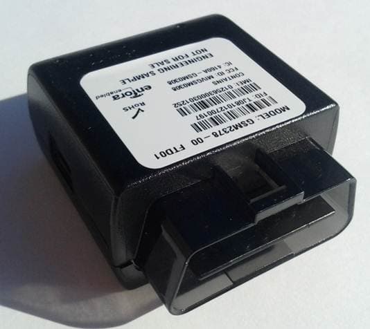
MIVRTT2211
Jan 22, 2013CDMA Licensed Transmitter
Equipment Class
PCB - PCS Licensed Transmitter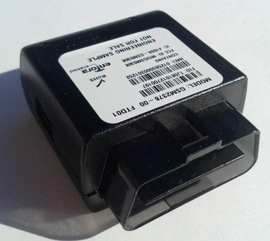
MIVGSM2378
Dec 23, 2012PCS GSM/ GPRS Licensed Transmitter
Equipment Class
PCB - PCS Licensed Transmitter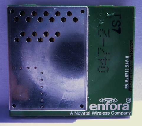
MIVCNN0301
May 10, 20121XRTT Multi-Band M2M OEM Module
Equipment Class
PCB - PCS Licensed Transmitter
MIVGSM2428
Jun 15, 2011GSM/ GPRS Personal Tracker
Equipment Class
JBP - Part 15 Class B Computing Device Peripheral
MIVGSM5218
Mar 15, 2011GSM/GPRS Asset Tracker
Equipment Class
PCB - PCS Licensed Transmitter