MIVGSM0103MAlpine 919 GPRS Modem
Novatel Wireless Inc.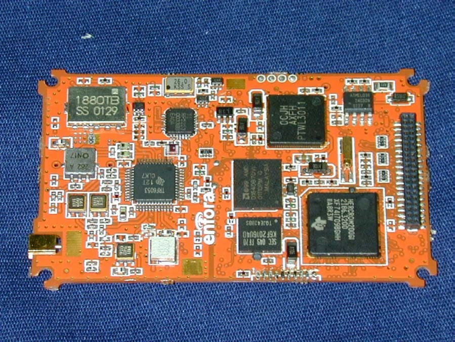
Click to zoom
Application Details
- Equipment Class
- TNB - Licensed Non-Broadcast Station Transmitter
- Date of Grant
- Feb 21, 2002
- Application Purpose
- Original Equipment
- Date of Application
- Nov 27, 2001
- Equipment Note
- Alpine 919 GPRS Modem
- Frequency Range
- 1850.00000000 - 1910.00000000
- Company
- Novatel Wireless Inc.
- Country
- Canada
Documents & Files
Document Text
Text extracted from the exhibit documents filed with the FCC. Open a document above to read the original.
Users Manual
Document Control Number: GSM1001BE001MAN rr User's Manual Enabler-G Revision History Rev Date ECN No. Author Description A 11/19/2001 N/A M. Cutchins / D. Rutledge Initial Release CONFIDENTIAL AND PROPRIETARY INFORMATION Do not duplicate or distribute without express permission from Enfora Inc. © 2001 Enfora, Inc This manual is copyrighted. All rights are reserved. No portion of this document may be copied, photocopied, reproduced, translated or reduced to any electronic medium or machine form without prior consent in writing from Enfora, Inc. © 2001 Enfora, Inc. The information in this document is subject to change without notice and does not represent a commitment on the part of Enfora, Inc. All product names mentioned in this document are the trademark of their respective owners. Enfora, Inc. 661 E. 18 th Street Plano, Texas 75074-5601 USA Phone: (972)633-4400 Fax:: (972)633-4444 Technical Support For problems stemming from your network access, contact your GPRS carrier service. For technical support and customer service dealing with the modem itself, contact Enfora, inc. by any of the following methods: Web site: www.enfora.com Phone: 972-633-2373 Email: [email protected] Before you contact Technical Support, please have your modem’s Equipment Identifier (EID) number ready for the Technical Support representative. CONFIDENTIAL - SEE CONFIDENTIALITY RESTRICTIONS ON TITLE PAGE Page 2 of 14 1.0 Introduction This document includes a feature overview, product specifications, mechanical information, and basic user information for Enfora’s Enabler-G, an embedded OEM GPRS Class C modem. This low cost device is packaged in a small form-factor to facilitate a variety of embedded applications. It offers features and functions similar to Enfora’s Enabler-A and Spider-O CDPD modems. 2.0 General Description The Enabler-G is a self-contained General Packet Radio Service (GPRS) Class-C modem containing all functionality, to include RF and digital control, required to perform wireless data transfer over a GPRS network. Enabler-G has been designed to work as an embedded component in lap top PCs and other mobile platforms as well as handheld or portable host devices. 3.0 Safety and Regulatory Compliance This unit complies with specifications for a GPRS Class-C full-duplex modems with a maximum transmit output power of 0.6 Watts. This Enabler-G complies with US CFR 47, Part 24 Subpart E and Part 15 of the FCC Rules and Regulations and Canada RSS-188. Detailed Regulatory and safety statements are provided following Section 10.0 of this Manual. Basic safety precautions and guidelines for such devices must be observed, such as: • Do not expose the device to fire, open flames, or extreme thermal conditions. • Do not spill liquids on the device. • Do not disassemble or attempt to modify the device without he express written consent of Enfora. • Do not attempt to repair the device The Enabler-G complies with the FCC RF emission and hazard requirements when installed and operated within the constraints and limitations specified in this manual. Enfora is not liable for injury to personnel 4.0 GPRS Background General Packet Radio Services (GPRS) is a packet based wireless communication service that can deliver variable data rates as a function of assigned timeslots and maintain continuous connection to the Internet for mobile subscribers on Global System for Mobile (GSM) Network worldwide. Since GPRS is based on GSM communication, it can be single, dual or triple band depending on the area of the service, it will complement existing services such as circuit switched cellular phone connections and the Short Message Service (SMS). In general, GPRS packet-based service should cost users less than circuit-switched services, since their communication channels are being used on a shared-use, as-packets-are-needed basis rather than dedicated only to one user at a time. Once GPRS becomes available, mobile users of a virtual private network (VPN) will be able to access their private networks continuously rather than through a dial-up connection. GPRS will also complement Bluetooth, a standard for replacing wired connections between devices with wireless radio connections. In addition to the Internet Protocol (IP), GPRS supports X.25, a packet-based protocol that is used mainly in Europe and Asia Pacific. GPRS is an evolutionary step toward Enhanced Data GSM Environment (EDGE) and Universal Mobile Telephone Service (UMTS). CONFIDENTIAL - SEE CONFIDENTIALITY RESTRICTIONS ON TITLE PAGE Page 3 of 14 The key benefit with GPRS is the ability to sustain a permanent data connection allowing a free flow of information for the mobile user. The data through put in GPRS will be significantly higher due to the ability of GPRS mobile terminals to transmit and receive more information than standard GSM terminals. The GSM communication system, in general, is standardized to operate in multiple bands, primarily, the 900 MHz band which is assigned PGSM, EGSM, RGSM for short, 1800 MHz band which is assigned DCS and the 1900 MHz band which is assigned PCS. Both the GSM and DCS band are used globally for mobile voice communication. The PCS 1900 is used in North, Central and South America. • Enabler-G Model No. GSM0102 900/1800 MHz • Enabler-G Model No. GSM0103 900/1900 MHz Although the GSM digital voice standard has existed for well over a decade, it wasn’t until recently that the demand for wireless data capability has increased. GPRS is a protocol within the GSM standard which was developed to address the need for data only transmission. Although the GSM voice protocol does support data transmission, it is limited in data rate due to overhead within the voice protocol. What the GRPS allows is a faster data rate that is adaptive as well as being packet based. 5.0 Mechanical Characteristics Basic package dimensions and form factor information is provided in the following figures. 5.1 Connectors Control Connector The connector used to in…
Text truncated - open the document above for the full version.
Block Diagram
RF Ant e nna Co n n ect o r PC S_ T X D u a l ba nd Tr an s cei v e r Bl o c k Dual Ban d RF S w i t c h Du al Ban d Di r ect i o n a l Co upl e r Dual Ban d P A PA R F Det ect o r Du a l Ba n d VCO 0° 90° ÷ 2 RX _ I P RX _ Q P 0° 90° ÷ N ÷ R EG S M PC S PFD TX _ I P TX_QP EGSM_T X PC S_ R X EGSM_R X HB P C S Di el ect r i c F ilt e r LB E G S M RF S a w f ilt e r HB PCS RF S a w f ilt e r LB E G S M RF S a w f ilt e r IF B P F RF o u t IFo u t 26M Hz VCT C X F unctio n al Block Diagr am Alpine 919 Rev. 2 G P RS M o dem By MM 10/11/01 Pa d Pa d NC Pa d RF Pad ÷ 2 RX _ I N RX _ Q N TX_IN TX_QN SR A M FL A S H SIM D 00-D 1 5 D 00-D 1 5 A 01-A 1 7 A 01-A 2 0 SI M SI M BA S E B AND B a s e ba nd C o d e c Upr o c & DS P Du al Ban d PL L S y n t h e s i zer 13M H z LB E G S M LN A HB P C S LNA
Cover Letter(s)
November 7, 2001 SUBJECT: REQUEST FOR CONFIDENTIALITY Enfora, Inc. hereby requests confidentiality with regard to the following documents in the filing for equipment approval identified by FCC ID No. MIVGSM0103M. (1) Schematic diagrams contained in electronic files identified below: • ALP0103MG101SCH3_1 It is the opinion of Enfora, Inc. that disclosure of this information would result in significant loss of revenue. This information should be kept confidential for at least 3 years. Durward E. Rutledge, P.E. Durward E. Rutledge, P.E. Vice President of Product Integrity Enfora, Inc. 661 E. 18 th Street Plano, Texas 75074-5601 661 East 18 th Street Plano, Texas 75074-5601 972-633-4400 Tel 972-633-4444 Fax www.nextcell.com
Cover Letter(s)
661 East 18 th Street Plano, Texas 75074-5601 972-633-4400 Tel 972-633-4444 Fax www.nextcell.com Federal Communications Commission 7435 Oakland Mills Road Columbia, MD 21046 USA Authority to Act as Agent to the Federal Communications Commission On our behalf, I appoint Nemko Dallas, Inc. to act as agent in the preparation of this application for equipment authorization to the Federal Communications Commission. I certify that submitted Exhibits properly describe the device or system for which equipment authorization is sought. I also certify that each unit manufactured, imported or marketed, as defined in the Commission's regulations will have affixed to it a label identical to that submitted for approval with this application. APPLICANT ANTI-DRUG ABUSE CERTIFICATION: In signing this letter, Applicant certifies that, in the case of an individual applicant, he or she is not subject to a denial of federal benefits, that includes FCC benefits, pursuant to Section 5301 of the Anti-Drug Abuse Act of 1988, 21 U.S.C. 853(a), or, in the case of a non-individual applicant (e.g. corporation, partnership or other unincorporated association), no party to the application is subject to a denial of federal benefits, that includes FCC benefits, pursuant to that section. For the definition of a "party" for these purposes, see 47 CFR 1.2002(b). Dated this 13th Day of August 2001 Agency agreement expiration date: By: Durward E. Rutledge, P.E. Title: Vice President Product Integrity Telephone: 972-437-3342 Applicant: Enfora, Inc. 661 East 18 th Street Plano, Texas 75074-5601
Cover Letter(s)
BASICS PER CLIENT 1 Number of PCS channels: 298 Channel Number Allocation: 512 to 810 2 Xtal Clock Frequency: 32.7868 KHz and 26 MHz 3 Power Requirement: 3.3 V min @ 1.2 Amp 5.0 V max @ 0.75 Amp 4 IF Frequency: Receive IF = 282 MHz Transmit IF = 181 MHz Receive RF LO = 1678.2 MHz Receive IF LO = 564 MHz Transmit RF LO = 1699.2 MHz Transmit IF LO = 543 MHz 5 Theory of Operation: Woking on it. CSP 6 Test Fixture Model : Alpine SDK P/N ALP105MG101ASY 7 Rated Output Power: Power Class 1 1W, 30 dBm +/- 2dB max output 1mW, 0 dBm +/-4 dB min output
External Photos
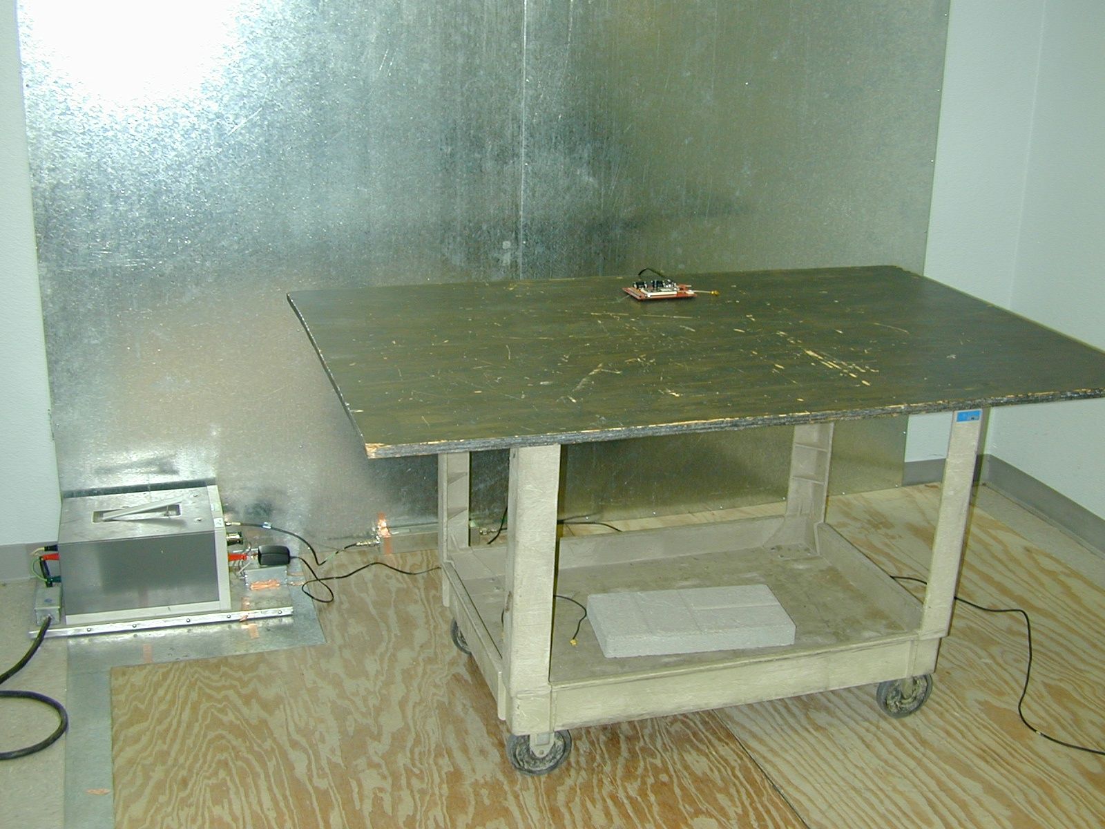
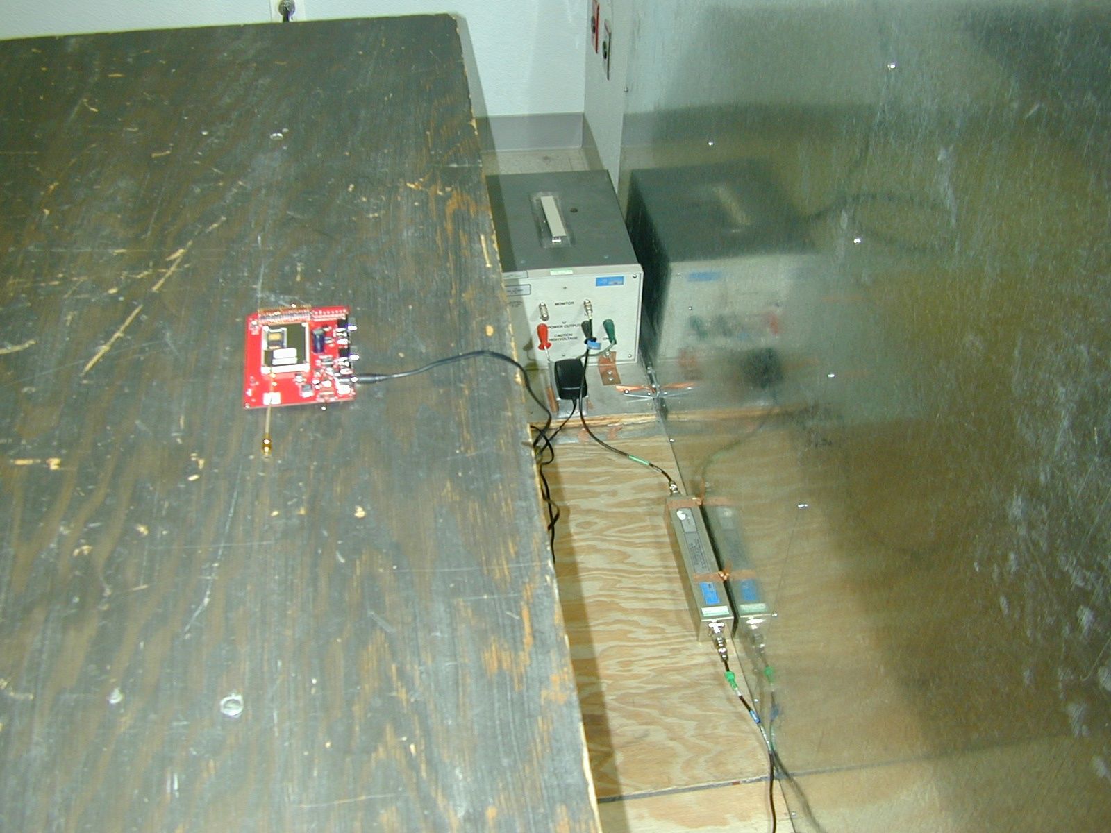
Internal Photos External Photos Test Set Up Photos
ID Label/Location Info
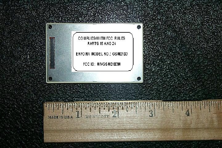
PRIMARY LABEL (located on device) COMPLIES WITH FCC RULES PARTS 15 AND 24 ENFORA MODEL NO.: GSM0103 FCC ID: MIVGSM0103M Alternate Label (if space permitted) ENFORA Enabler-G MODEL NO.: GSM0103 EID NO.: XX XX XX XX XX XX FCC ID: MIVGSM0103M Canada: XXXXXXX This device has been tested and found to comply with Part 15 and Part 24 of FCC Rules. Operation is subject to the following conditions: (1) This device must not cause harmful interference; (2) This device must accept any interference received, including interference that may cause undesired operation.
ID Label/Location Info
This device has not been authorized as required by the rules of the Federal Communications Commission. This device is not, and may not be, offered for sale or lease, or sold or leased, until authorization is obtained.
Internal Photos
Internal Photos External Photos Test Set Up Photos
Operational Description
Functional Description For Alpine 919 GPRS Modem Enfora, Inc. 661 E. 18th Plano, TX 75074 Revision History Date Rev Author Description 10/15/2000 0.0 CSP Preliminary WARNING: This document contains proprietary information and must not be reproduced without the prior written consent of Enfora, Inc. 2 TABLE OF CONTENTS 1. GPRS BACKGROUND............................................................................................................................ 3 2. THEORY OF OPERATION.................................................................................................................... 3 2.1 INTRODUCTION.................................................................................................................................. 3 2.2 ABBREVIATION................................................................................................................................... 4 2.3 FREQUENCY ALLOCATION (M-ES)....................................................................................................... 4 2.3.1 Power control....................................................................................................................... 5 2.4 RECEIVER SECTION............................................................................................................................. 6 2.4.1 RF Switch.............................................................................................................................. 6 2.4.2 LNA and First Conversion.................................................................................................... 6 2.4.3 First IF Stage......................................................................................................................... 6 2.4.4. AGC IF, I&Q Demodulation................................................................................................. 6 2.4.5. Baseband Amplifier, DC offset compensation................................................................. 6 2.5 TRANSMIT PATH................................................................................................................................7 2.5.1 I&Q Modulation, Tx VCO..................................................................................................... 7 2.5.2 Loop Filter............................................................................................................................. 7 2.5.3 PA, Directional Coupler...................................................................................................... 7 2.6 DIGITAL BASEBAND............................................................................................................................ 7 2.6.1 Memory.................................................................................................................................. 7 2.6.2 Processor(s)........................................................................................................................... 7 2.6.3 CODEC.................................................................................................................................... 7 2.7 BLOCK DIAGRAM................................................................................................................................8 3 1. GPRS Background GPRS General Packet Radio Services (GPRS) is a packet based wireless communication service that can deliver variable data rates as a function of assigned timeslots and maintain continuous connection to the Internet for mobile subscribers on Global System for Mobile (GSM) Network worldwide. Since GPRS is based on GSM communication, it can be single, dual or triple band depending on the area of the service, it will complement existing services such as circuit switched cellular phone connections and the Short Message Service (SMS). In general, GPRS packet-based service should cost users less than circuit-switched services, since their communication channels are being used on a shared-use, as-packets-are-needed basis rather than dedicated only to one user at a time. Once GPRS becomes available, mobile users of a virtual private network (VPN) will be able to access their private networks continuously rather than through a dial-up connection. GPRS will also complement Bluetooth, a standard for replacing wired connections between devices with wireless radio connections. In addition to the Internet Protocol (IP), GPRS supports X.25, a packet-based protocol that is used mainly in Europe and Asia Pacific. GPRS is an evolutionary step toward Enhanced Data GSM Environment (EDGE) and Universal Mobile Telephone Service (UMTS). The key benefit with GPRS is the ability to sustain a permanent data connection allowing a free flow of information for the mobile user. The data through put in GPRS will be significantly higher due to the ability of GPRS mobile terminals to transmit and receive more information than standard GSM terminals. 2. Theory of Operation 2.1 Introduction The GSM communication system, in general, is standardized to operate in multiple bands, primarily, the 900 Mhz band which is assigned PGSM, EGSM, RGSM for short, 1800 Mhz band which is assigned DCS and the 1900 Mhz band which is assigned PCS. Both the GSM and DCS band are used globally for mobile voice communication. The PCS 1900 is used in North, Central and South America. Although the GSM digital voice standard has existed for well over a decade, it wasn’t until recently that the demand for wireless data capability has increased. GPRS is a protocol within the GSM standard which was developed to address the need for data only transmission. Although the GSM voice protocol does support data transmission, it is limited in data rate due to overhead within the voice protocol. What the GRPS allows is a faster data rate that is adaptive as well as being packet based. The Enabler transceiver design is based on a proprietary chip set that complements size, cost and power consumption. Enabler-G919 is a …
Text truncated - open the document above for the full version.
RF Exposure Info
Prediction of MPE limit at a given distance Equation from page 18 of OET Bulletin 65, Edition 97-01 where:S = power density P = power input to the antenna G = power gain of the antenna in the direction of interest relative to an isotropic radiator R = distance to the center of radiation of the antenna Maximum peak output power at antenna input terminal:30.00(dBm) Maximum peak output power at antenna input terminal:1000(mW) Antenna gain(typical):0 (dBi) Maximum antenna gain:1 (numeric) Prediction distance:20(cm) Prediction frequency:1900(MHz) MPE limit for uncontrolled exposure at prediction frequency:1 (mW/cm^2) Power density at prediction frequency: 0.198944(mW/cm^2) Maximum allowable antenna gain: 7.012699(dBi) 2 4R PG S π =
Test Report
Nemko Test Report:1L0486RUS1 Applicant:Enfora 661 East 18 th Street Plano, TX 75074-5601 Equipment Under Test:Alpine GPRS 919 In Accordance With:FCC Part 24, Subpart E Broadband PCS Subscriber Station Tested By:Nemko Dallas Inc. 802 N. Kealy Lewisville, TX 75057-3136 Authorized By: Tom Tidwell, RF Group Manager Date:10/25/01 Total Number of Pages:35 Nemko Dallas FCC PART 24, SUBPART E BROADBAND PCS SUBSCRIBER STATION EQUIPMENT: Alpine GPRS 919 PROJECT NO.: 1L0486RUS1 Page 2 of 35 Table of Contents Section 1. Summary of Test Results.....................................................................................3 Section 2. General Equipment Specification.........................................................................5 Section 3. RF Power Output................................................................................................7 Section 4. Occupied Bandwidth...........................................................................................8 Section 5. Spurious Emissions at Antenna Terminals.........................................................12 Section 6. Field Strength of Spurious.................................................................................21 Section 7. Frequency Stability............................................................................................24 Section 8. Test Equipment List..........................................................................................25 ANNEX A - TEST METHODOLOGIES..................................................................................26 ANNEX B - TEST DIAGRAMS..............................................................................................32 Nemko Dallas FCC PART 24, SUBPART E BROADBAND PCS SUBSCRIBER STATION EQUIPMENT: Alpine GPRS 919 PROJECT NO.: 1L0486RUS1 Page 3 of 35 Section 1.Summary of Test Results Manufacturer:Enfora Model No.:Alpine GPRS 919 Serial No.:1 General:All measurements are traceable to national standards. These tests were conducted on a sample of the equipment for the purpose of demonstrating compliance with FCC Part 24, Subpart E. New SubmissionProduction Unit Class II Permissive ChangePre-Production Unit THIS TEST REPORT RELATES ONLY TO THE ITEM(S) TESTED. THE FOLLOWING DEVIATIONS FROM, ADDITIONS TO, OR EXCLUSIONS FROM THE TEST SPECIFICATIONS HAVE BEEN MADE. See “ Summary of Test Data”. NVLAP LAB CODE: 100426-0 Nemko Dallas Inc. authorizes the above named company to reproduce this report provided it is reproduced in its entirety and for use by the company’s employees only. Any use which a third party makes of this report, or any reliance on or decisions to be made based on it, are the responsibility of such third parties. Nemko Dallas Inc. accepts no responsibility for damages, if any, suffered by any third party as a result of decisions made or actions based on this report. This report applies only to the items tested. Nemko Dallas FCC PART 24, SUBPART E BROADBAND PCS SUBSCRIBER STATION EQUIPMENT: Alpine GPRS 919 PROJECT NO.: 1L0486RUS1 Page 4 of 35 Summary Of Test Data NAME OF TESTPARA. NO. SPEC.RESULT RF Power Output24.232100WComplies Occupied Bandwidth (GPRS)24.238Not Specified Included for information Spurious Emissions at Antenna Terminals 24.238(a)-13 dBmComplies Field Strength of Spurious Emissions 24.238(a) -13 dBm E.I.R.P. Complies Frequency Stability24.235 ± 0.05 ppm Complies Nemko Dallas FCC PART 24, SUBPART E BROADBAND PCS SUBSCRIBER STATION EQUIPMENT: Alpine GPRS 919 PROJECT NO.: 1L0486RUS1 Page 5 of 35 Section 2.General Equipment Specification Supply Voltage Input: 3.3 - 5 Vdc Frequency Bands: Block A : 1850 – 1865 MHz Block B : 1865 – 1870 MHz Block C : 1870 – 1885 MHz Block D : 1885 – 1890 MHz Block E : 1890 – 1895 MHz Block F : 1895 – 1910 MHz GPRS 200K0G7W Type of Modulation and Designator: Output Impedance: 50 ohms RF Output (Rated): 1 Watt Nemko Dallas FCC PART 24, SUBPART E BROADBAND PCS SUBSCRIBER STATION EQUIPMENT: Alpine GPRS 919 PROJECT NO.: 1L0486RUS1 Page 6 of 35 System Description The GSM communication system, in general, is standardized to operate in multiple bands, primarily, the 900 MHz band which is assigned PGSM, EGSM, RGSM for short, 1800 MHz band which is assigned DCS and the 1900 MHz band which is assigned PCS. Both the GSM and DCS band are used globally for mobile voice communication. The PCS 1900 is used in North, Central and South America. The GSM 900 band is disabled for these markets. Although the GSM digital voice standard has existed for well over a decade, it wasn’t until recently that the demand for wireless data capability has increased. GPRS is a protocol within the GSM standard, which was developed to address the need for data only transmission. Although the GSM voice protocol does support data transmission, it is limited in data rate due to overhead within the voice protocol. What the GRPS allows is a faster data rate that is adaptive as well as being packet based. The Enabler transceiver design is based on a proprietary chip set that complements size, cost and power consumption. Enabler-G919 is a dual band EGSM 900 MHz and PCS 1900 MHz design in a 1.7” x 2.7” x 0.2” housing. It communicates via an RF antenna port and a multiple pin digital connector. The RF and digital processors are design to operate at 3.8V. The band is selected at the front end via a high power RF Switch. This signal is then prefiltered to remove large out-of-band signals from compressing the LNA. It is then filtered again to prevent the down converter from converting unwanted signal into the IF band. An IF filter is used to set the channel BW to about 200 KHz. This high selectivity IF filter will allow the Enabler to operate through a high dynamic range. The AGC amplifier in conjunction with the DSP chip will automatically adjust the gain to maintain a constant baseband signal. The I&Q demodulator converts the RF signal into 2 baseband signals called Rx I & Q. This prefiltered I&Q signal is sent to the DSP processor w…
Text truncated - open the document above for the full version.
Contact Information
Applicant
Todd Gallagher(Manager, Regulatory Engineering)
Technical Contact
Nemko Dallas, Inc.David Light
[email protected]972-436-9600
802 N. Kealy · Lewisville, Texas · United States
Non-Technical Contact
Nemko Dallas, Inc.Davida Hanson
[email protected]972-436-9600
Test Firm
Nemko Dallas, Inc.Michael Cantwell
Technical Specifications
| # | Rule Parts | Frequency Range | Power Output | Emission | Tolerance |
|---|---|---|---|---|---|
| 1 | 24E | 1.85 GHz - 1.91 GHz | 912.00 mW | 200KGXW | 0.0500000000 ppm |
Other Applications from Novatel Wireless Inc.
MIVRTT2211
Jan 22, 2013CDMA Licensed Transmitter
Equipment Class
PCB - PCS Licensed Transmitter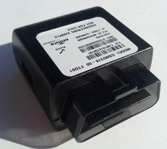
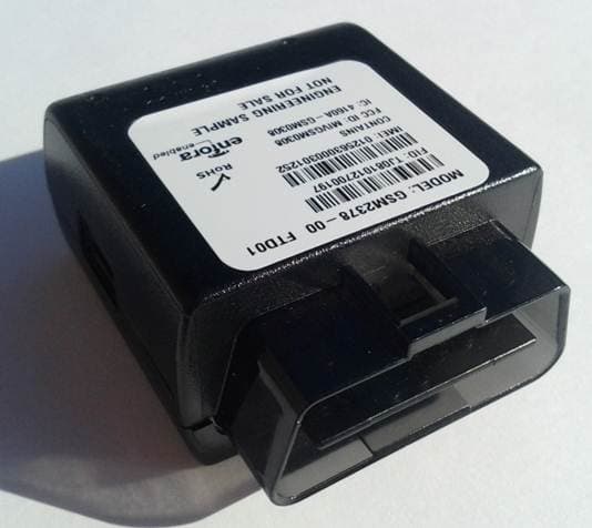
MIVGSM2378
Dec 23, 2012PCS GSM/ GPRS Licensed Transmitter
Equipment Class
PCB - PCS Licensed Transmitter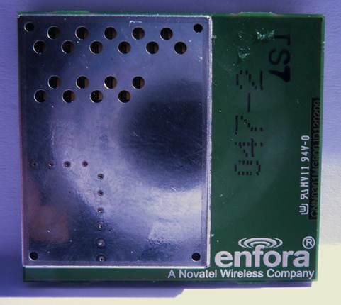
MIVCNN0301
May 10, 20121XRTT Multi-Band M2M OEM Module
Equipment Class
PCB - PCS Licensed Transmitter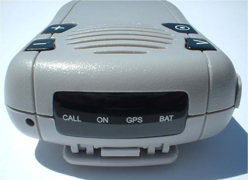
MIVGSM2428
Jun 15, 2011GSM/ GPRS Personal Tracker
Equipment Class
JBP - Part 15 Class B Computing Device Peripheral
MIVGSM5218
Mar 15, 2011GSM/GPRS Asset Tracker
Equipment Class
PCB - PCS Licensed Transmitter