MIVGSM0308Wireless Modem
Novatel Wireless Inc.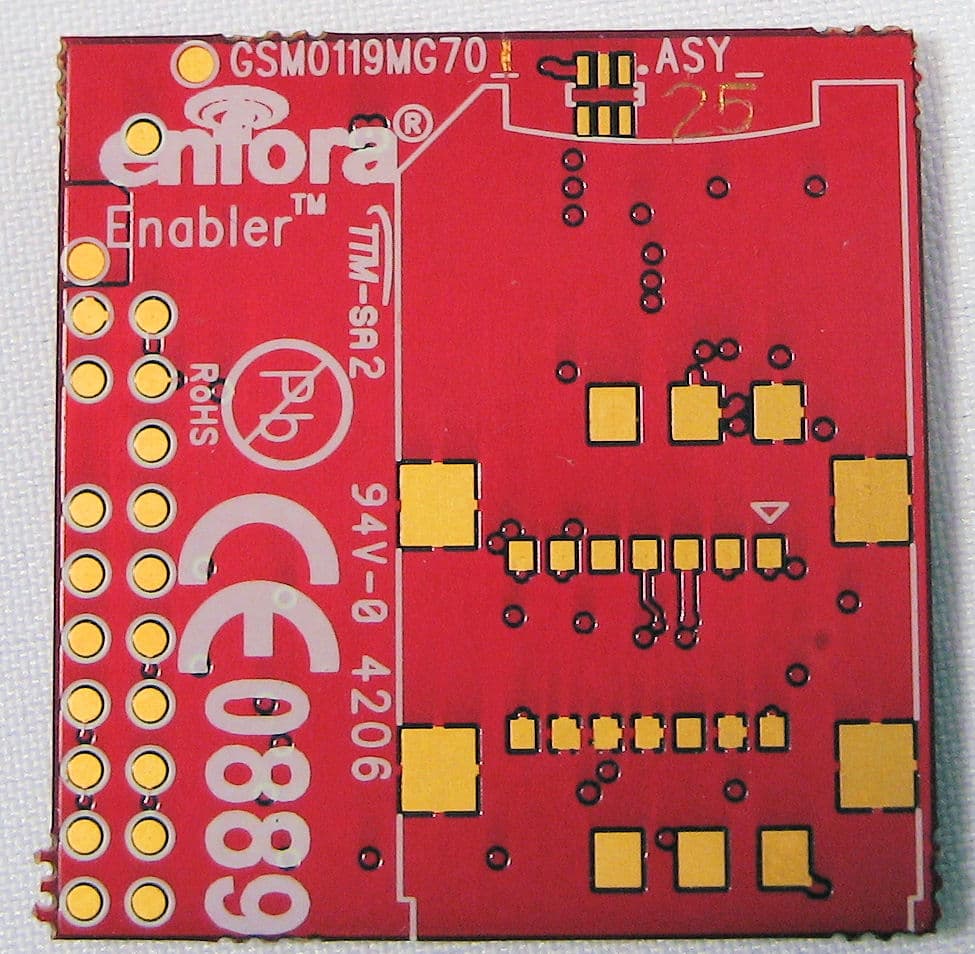
Click to zoom
Application Details
- Equipment Class
- PCB - PCS Licensed Transmitter
- Date of Grant
- Feb 14, 2007
- Application Purpose
- Original Equipment
- Date of Application
- Feb 13, 2007
- Equipment Note
- Wireless Modem
- Frequency Range
- 824.20000000 - 848.80000000
- Company
- Novatel Wireless Inc.
- Country
- Canada
Documents & Files
Document Text
Text extracted from the exhibit documents filed with the FCC. Open a document above to read the original.
Users Manual
GSM0308PB001 Enfora, Inc. 661 E. 18 th Street Plano Texas 75074 www.enfora.com Enfora Enabler III-G Integration Guide Version: DRAFT Enfora Enabler III-G Modem Integration Guide Document Title: Enfora Enabler III-G Modem Integration Guide Version: DRAFT Date: 1/31/07 Status: DRAFT Document Control ID: GSM0308PB001 General All efforts have been made to ensure the accuracy of material provided in this document at the time of release. However, the items described in this document are subject to continuous development and improvement. All specifications are subject to change without notice and do not represent a commitment on the part of Enfora, Inc. Enfora, Inc. will not be responsible for any loss or damages incurred related to the use of information contained in this document. This product is not intended for use in life support appliances, devices or systems where a malfunction of the product can reasonably be expected to result in personal injury. Enfora, Inc. customers using, integrating, and/or selling this product for use in such applications do so at their own risk and agree to fully indemnify Enfora, Inc. for any damages resulting from illegal use or resale. Copyright Complying with all applicable copyright laws is the responsibility of the user. Without limiting the rights under copyright, no part of this document may be reproduced, stored in or introduced into a retrieval system, or transmitted in any form or by any means (electronic, mechanical, photocopying, recording or otherwise), or for any purpose, without the express written permission of Enfora, Inc. Enfora may have patents, patent applications, trademarks, copyrights or other intellectual property rights covering subject matter in this document. Except as expressly provided in any written license agreement from Enfora, the furnishing of this document does not give you any license to these patents, trademarks, copyrights or other intellectual property. ©2002, 2003, 2004, 2005, 2006, 2007 Enfora, Inc. All rights reserved. Enabler and Spider are either registered trademarks or trademarks of Enfora, Inc. in the United States. GSM0308PB001 Version DRAFT – 2/9/2007 Enfora Enabler III-G Modem Integration Guide Table of Contents 1. SAFETY PRECAUTIONS.................................................................................................................................1 1.1. IMPORTANT SAFETY INFORMATION................................................................................................................1 2. REGULATORY COMPLIANCE FCC.............................................................................................................1 2.1. INTEGRATION CONSIDERATIONS AND INSTALLATION REQUIREMENTS...........................................................1 2.2. DISCLAIMER...................................................................................................................................................3 3. MANUAL OVERVIEW......................................................................................................................................4 3.1. REVISION HISTORY.........................................................................................................................................4 3.2. REFERENCE DOCUMENTS...............................................................................................................................5 3.2.1. Enfora Enabler III-G Product Documentation......................................................................................5 3.2.2. GSM Device Specifications....................................................................................................................6 3.2.3. US Government......................................................................................................................................6 3.2.4. Federal Communications Commission (FCC).......................................................................................6 3.2.5. FCC Office of Engineering and Technology (OET)..............................................................................6 3.2.6. Industry Canada....................................................................................................................................7 3.2.7. Environmental Regulations....................................................................................................................7 3.2.8. Mechanical Specifications.....................................................................................................................7 3.2.9. RF and EMI Specifications....................................................................................................................7 4. INTRODUCTION...............................................................................................................................................8 4.1. PRODUCT OVERVIEW......................................................................................................................................8 4.2. KEY FEATURES OF THE ENABLER III MODULE...............................................................................................8 4.3. PROVIDING MULTI-BAND OPERATION.........................................................................................................10 4.4. WIRELESS DATA APPLICATION POSSIBILITIES..............................................................................................10 4.5. GSM/GPRS SYSTEM OVERVIEW.................................................................................................................11 4.6. SUMMARY OF FEATURES FOR THE ENABLER III-G MODULE........................................................................13 4.7. GENERAL LAYOUT GUIDELINES FOR ENFORA GSM MODULES.....................................................................15 5. TECHNICAL SPECIFICATIONS..................................................................................................…
Text truncated - open the document above for the full version.
Cover Letter(s)
Enfora, Inc. 661 E. 18 th Street Plano, TX 75074-5601 (972) 633-4400 Fax (972) 633-4444 31 st January 2007 REQUEST FOR CONFIDENTIALITY Telecommunication Certification Body AmericanTCB, Inc. 6731 Whittier Avenue McLean, VA 22101 Subject: Certification Application FCC ID: MIVGSM0308 Enfora, Inc., requests confidentiality with regard to the following documents in the filing for equipment approval identified by FCC ID MIVGSM0308, Enfora PN GSM0308 (1) Schematic Diagrams contained in electronic files Enfora.GSM0308.GSM0119MG801_Rev4.Schematic.pdf (2) Block Diagram located in electronic file Enfora.GSM0308.BlockDiagram.pdf. (3) Bill Of Materials (BOM) located in electronic file Enfora.GSM0308.BOMs.xls. It is the opinion of Enfora, Inc., that disclosure of this information would result in significant loss of revenue. These documents are also covered under multiple non-disclosure agreements with other companies. This information should be kept confidential for 5 years. Sincerely Rob Holden Manager, Compliance Engineering Enfora, Inc. 661 E. 18 th Street Plano, TX 75074 972-633-4400
Cover Letter(s)
American Telecommunications Certification Body Inc. 6731 Whittier Ave, McLean, VA 22101 February 6, 2007 RE: FCC ID: MIVGSM0308_ATCB004517 Attention: Tom Tidwell I have a few comments on this Application. Please note that further comments may arise in response to answers provided to the questions below. 1. Please note that the FCC states that the actual frequencies used ar to be on the grant. This means that for this application the following frequencies are to be on the grant: 824.2-848.8MHz and 1850.2-1909.8MHz. Please correct the 731 to reflect the actual frequencies for this application. 2. Please explain if this is a licensed modular transmitter application. 3. Please explain how the label is permanently attached to the device. 4. Please note that it appears that the manual uses 7watts for the part 22 MPE information. Please note that this is not correct. Please note the highest gain antenna usable for this device under part 22 MPE at 824.2MHz to keep the 20cm separation would be 2.1dBi (32.3+2.1=34.4dBm or about 2.75W. For the part 24 MPE the highest gain antenna usable would be about 5.8dB. However, as noted in the manual, the limiting factor at 1999MHz PCS is the 2W eiro allowed for mobile devices. This means that the highest gain antenna usable for the part 24 configuration would be less than that of the part 22 configuration or about 1.84dBi. Please correct the manual to reflect the actual maximum antenna gains for this device. 5. Please correct your MPE reports to reflect the actual measured antenna conducted power form the report. For part 22, as the highest power was measured at the 824MHz end and since this is the lower MPE rating this would be a power of 32.3dBm and an antenna gain of 2.1 and for part 24 this would be a power of 31.17 and a max antenna gain of 1.84dB. 6. Please note that the part 22 radiated spurious emissions data appears to be in EIRP and not ERP as required by the rules. Please correct the data to show ERP values for part 22. Dennis Ward mailto:[email protected] The items indicated above must be submitted before processing can continue on the above referenced application. Failure to provide the requested information may result in application termination. Correspondence should be considered part of the permanent submission and may be viewed from the Internet after a Grant of Equipment Authorization is issued. Please do not respond to this correspondence using the email reply button. In order for your response to be processed expeditiously, you must submit your documents through the AmericanTCB.com website. Also, please note that partial responses increase processing time and should not be submitted. Any questions about the content of this correspondence should be directed to the sender.
Cover Letter(s)
February 6, 2007 RE: FCC ID: MIVGSM0308_ATCB004517 Attention: Tom Tidwell I have a few comments on this Application. Please note that further comments may arise in response to answers provided to the questions below. 1. Please note that the FCC states that the actual frequencies used ar to be on the grant. This means that for this application the following frequencies are to be on the grant: 824.2-848.8MHz and 1850.2-1909.8MHz. Please correct the 731 to reflect the actual frequencies for this application. It was my understanding that this is the case only with unlicensed devices. I have updated the Form 731 in any case. 2. Please explain if this is a licensed modular transmitter application. My understanding was that FCC does not really provide for licensed modular approval. This device is sold for integration into various end products however. The purpose of the integration guide is to warn the integrator that the device can only be used in fixed and mobile rf exposure configurations and that a new approval must be obtained if the device is to be used in a Portable configuration. It looks like for previous certifications ITS did for these guys they put a note about the module but did not include “modular” in the description note. See the attached grant for a previous version of this device. 3. Please explain how the label is permanently attached to the device. The label is silk screened onto the PWB. 4. Please note that it appears that the manual uses 7watts for the part 22 MPE information. Please note that this is not correct. Please note the highest gain antenna usable for this device under part 22 MPE at 824.2MHz to keep the 20cm separation would be 2.1dBi (32.3+2.1=34.4dBm) or about 2.75W. For the part 24 MPE the highest gain antenna usable would be about 5.8dB. However, as noted in the manual, the limiting factor at 1999MHz PCS is the 2W eirp allowed for mobile devices. This means that the highest gain antenna usable for the part 24 configuration would be less than that of the part 22 configuration or about 1.84dBi. Please correct the manual to reflect the actual maximum antenna gains for this device. I agree that the 7 watts should be changed in the user manual. However, for the MPE prediction I believe it would be appropriate to use a duty cycle 0f 50% rather than 100% since the GSM technology has a source-based time duty cycle. In most cases the time slice for a GSM signal would be such that the duty cycle would be less than 50%. In this case the maximum gain for MPE compliance would be 4.5 dBi for GSM850 (to comply with MPE at 20 cm) and 2 dBi for GSM1900 (to comply with the maximum 2 watts eirp). Please see the revised MPE data sheets. For a fixed installation (antenna mounted on a permanent outdoor structure as per integration guide) with 2 meters minimum separation, a higher gain antenna could be used. 5. Please correct your MPE reports to reflect the actual measured antenna conducted power form the report. For part 22, as the highest power was measured at the 824MHz end and since this is the lower MPE rating this would be a power of 32.3dBm and an antenna gain of 2.1 and for part 24 this would be a power of 31.17 and a max antenna gain of 1.84dB. Please see above notes concerning duty cycle. 6. Please note that the part 22 radiated spurious emissions data appears to be in EIRP and not ERP as required by the rules. Please correct the data to show ERP values for part 22. See the revised FCC report with erp fs of spurious data .
Cover Letter(s)
Enfora, Inc. 661 E. 18 th Street Plano, TX 75074-5601 (972) 633-4400 Fax (972) 633-4444 AGENCY LETTER 31 st January 2007 American Telecommunication Certifications Body, Inc. To Whom It May Concern This is to certify that Enfora, Inc. authorises National Technical Systems, until otherwise notified, for applications to American Telecommunications Certification Body, Inc. (ATCB) We certify that we are not subject to a denial of Federal benefits, that include FCC benefits, pursuant to Section 5301 of the Anti-Drug Abuse Act of 1988, 21 U.S.C. § 862 because of a conviction for possession or distribution of a controlled substance. See 47 CFR 1.2002(b) for the definition of a "party" for these purposes. Sincerely Rob Holden Manager, Compliance Engineering Enfora, Inc. 661 E. 18 th Street Plano, TX 75074 972-633-4400
ID Label/Location Info
IMEI LABEL ENFORA INFO LABEL
Operational Description
GSM0308 Circuit Description Enfora, Inc. 661 E. 18 th Street Plano, TX 75074-5601 (972) 633-4400 Fax (972) 633-4444 January 29, 2007 GSM0308 Circuit Description General Description The GSM0308 Module utilizes the Texas Instruments Locosto digital signal processor/digital radio processor (DSP/DRP) integrated circuit. This DSP/DRP is highly integrated and provides all modem functions when combined with the TI Triton Lite analog and power management IC. RF amplification and routing is accomplished with a combined RF power amplifier/switch module. Radio Interface The Locosto DRP and RF amplifier/switch provide the complete RF front-end for the GSM/GPRS functions. The receiver section encompasses the RF switch, RF band-select SAW filters and the DRP. The DRP is directly integrated to the DSP on the same IC. All down conversion and signal processing is done directly within the DRP. The transmit section consists of a direct connection from DRP through the power amplifier/switch module to the RF connector port. All carrier generation and modulation is performed within the DRP. The DSP/DRP uses a digitally controlled crystal (26 MHz) oscillator (DCXO) that integrates the reference oscillator and varactor functionality. Baseband Interface The Locosto DSP provides all digital interfaces and control of the system. The Triton Lite analog and power management chip controls all power domains and analog interfaces. It utilizes input from a 32KHz crystal oscillator to provide real-time clock and synchronization for external interfaces. Triton also performs digital to analog translation and amplification for all audio interfaces.
Parts List/Tune Up Info
® Enfora, Inc. 661 E. 18 th Street Plano, TX 75074-5601 (972) 633-4400 Fax (972) 633-4444 January 26, 2007 Tune-Up Procedure Description for GSM0308 Power Adjustments The RF power output of the modem is preset during the manufacturing process via software- controlled adjustment of calibration parameters referenced to a base-station simulator. Under normal operation, the RF output power is maintained via an ALC circuit. Neither the integrator nor end-user has access to the calibration/power adjustment of the device. Frequency Adjustments Under normal operation, the transmitter uses a frequency synthesizer synchronized to a base- station clock, thus there are no frequency alignments that must be made. Scott Yarberry AVP, Product Development Enfora, L.P. 661 E. 18 th St Plano, TX 75074 972-633-4400
RF Exposure Info
Prediction of Maximum Permissible Exposure Equation from page 18 of OET Bulletin 65, Edition 97-01 where: S = power density P = power input to the antenna G = directional power gain of the antenna relative to an isotropic radiator R = distance to the center of radiation of the antenna *RF output power at antenna terminal(dBm):29.30 *RF output power at antenna terminal(W):0.851 Antenna gain for prediction(dBi):4.52.35 dBd Maximum antenna gain(numeric):2.8183829 Prediction distance(cm):20 Prediction frequency(MHz):849 Limit for uncontrolled exposure(mw/cm²): 0.533 S(mw/cm²) = :0.477 *A 50% duty cycle is used for this prediction based on the allowance in the Rules for source-based time averaging of the rf exposure levels. 50% was chosen as a conservative estimate of the dwell time of a GSM mobile carrier. A GSM TDMA frame is 4.615 msec. with eight 0.577 msec. transmit bursts during the frame length. One physical channel is one out of the eight bursts. The maximum number of bursts the mobile might transmit is two (1.154 msec. in each 4.615 msec. frame), or 25% of the time. Allowing for timing tolerances and other factors it is reasonable to use a 50% duty cycle factor for the rf exposure prediction. Thus 3 dB was subtracted from the measured peak power of 32.3 dBm for the purposes of this prediction. 2 4 PG S RΠ =
RF Exposure Info
Prediction of Maximum Permissible Exposure Equation from page 18 of OET Bulletin 65, Edition 97-01 where: S = power density P = power input to the antenna G = directional power gain of the antenna relative to an isotropic radiator R = distance to the center of radiation of the antenna *RF output power at antenna terminal(dBm):28.30 *RF output power at antenna terminal(W):0.676 Antenna gain for prediction(dBi):2 Maximum antenna gain(numeric):1.5848932 Prediction distance(cm):20 Prediction frequency(MHz):1910 Limit for uncontrolled exposure(mw/cm²): 1.000 S(mw/cm²) = :0.213 *A 50% duty cycle is used for this prediction based on the allowance in the Rules for source-based time averaging of the rf exposure levels. 50% was chosen as a conservative estimate of the dwell time of a GSM mobile carrier. A GSM TDMA frame is 4.615 msec. with eight 0.577 msec. transmit bursts during the frame length. One physical channel is one out of the eight bursts. The maximum number of bursts the mobile might transmit is two (1.154 msec. in each 4.615 msec. frame), or 25% of the time. Allowing for timing tolerances and other factors it is reasonable to use a 50% duty cycle factor for the rf exposure prediction. Thus 3 dB was subtracted from the measured peak power of 31.3 dBm for the purposes of this prediction. 2 4 PG S RΠ =
Test Report
This report and the information contained herein represent the results of testing test articles identified and selected by the client performed to specifications and/or procedures selected by the client. National Technical Systems (NTS) makes no representations, expressed or implied, that such testing is adequate (or inadequate) to demonstrate efficiency, performance, reliability, or any other characteristic of the articles being tested, or similar products. This report should not be relied upon as an endorsement or certification by NTS of the equipment tested, nor does it represent any statement whatsoever as to its merchantability or fitness of the test article, or similar products, for a particular purpose. This report shall not be reproduced except in full. NTS Plano, 1701 E. Plano Pkwy., Plano, TX 75074 Tel: (972) 509-2566, Fax: (972) 509-0073 Page 1 of 63 Certification Test Report CFR 47 FCC Part 22 and Part 24 Model: GSM0308-10 B2BRF GSM0308-11 B2BRF w/sim GSM0308-70 coax RF GSM0308-71 coax RF w/sim FCC ID NO. MIVGSM0308 Report Code: W7005-1 Revision: 2 Prepared for: Enfora, Inc. 661 E. 18 th St. Plano, TX 75074-5601 Author: Tom Tidwell, Manager of Wireless Services Issued: 9 February 2007 1701 E. Plano Parkway, Suite 150 Plano, Texas 75074 Phone: (972) 509-2566 Fax: (972) 509-0073 Model: GSM0308-10 B2BRF GSM0308-11 B2BRF w/ sim GSM0308-70 coax rf GSM0308-71 coax rf w/ sim Compliance Test Report FCC ID NO. MIVGSM0308 This report and the information contained herein represent the results of testing test articles identified and selected by the client performed to specifications and/or procedures selected by the client. National Technical Systems (NTS) makes no representations, expressed or implied, that such testing is adequate (or inadequate) to demonstrate efficiency, performance, reliability, or any other characteristic of the articles being tested, or similar products. This report should not be relied upon as an endorsement or certification by NTS of the equipment tested, nor does it represent any statement whatsoever as to its merchantability or fitness of the test article, or similar products, for a particular purpose. This report shall not be reproduced except in full. NTS Plano, 1701 E. Plano Pkwy., Plano, TX 75074 Tel: (972) 509-2566, Fax: (972) 509-0073 Page 2 of 63 Report Summary NTS Plano Accreditation Numbers: FCC: 101741 IC: 46405-4319 File # IC-4319A Applicant: Enfora, Inc. 661 E. 18 th St. Plano, TX 75074-5601 Customer Representative: Rob Holden EUT Description: EUT Description Manufacturer Model RevisionSerial Number The EUT is a wireless transceiver that operates in the GSM 850 and GSM1900 bands in North America Enfora, Inc. GSM0308-10 B2BRF GSM0308-11 B2BRF w/sim GSM0308-70 coax RF GSM0308-71 coax RF w/sim X X Model: GSM0308-10 B2BRF GSM0308-11 B2BRF w/ sim GSM0308-70 coax rf GSM0308-71 coax rf w/ sim Compliance Test Report FCC ID NO. MIVGSM0308 This report and the information contained herein represent the results of testing test articles identified and selected by the client performed to specifications and/or procedures selected by the client. National Technical Systems (NTS) makes no representations, expressed or implied, that such testing is adequate (or inadequate) to demonstrate efficiency, performance, reliability, or any other characteristic of the articles being tested, or similar products. This report should not be relied upon as an endorsement or certification by NTS of the equipment tested, nor does it represent any statement whatsoever as to its merchantability or fitness of the test article, or similar products, for a particular purpose. This report shall not be reproduced except in full. NTS Plano, 1701 E. Plano Pkwy., Plano, TX 75074 Tel: (972) 509-2566, Fax: (972) 509-0073 Page 3 of 63 Test Summary Deviations from: Appendix Test/Requirement Description Base Standard Test Basis NTS Procedure Pass / Fail Applicable Rule Parts A RF Power Output No No No PASS CFR 47, Part 2, Para. 2.1046 CFR 47, Part 22, Para. 22.913 CFR 47, Part 24, Para.24.232 B Modulation Characteristics No No No PASS CFR 47, Part 2, Para. 2.1047 C Occupied Bandwidth No No No PASS CFR 47, Part 2, Para. 2.1049 CFR 47, Part 22, Para. 22.917 CFR 47, Part 24, Para. 24.238 D Spurious Emissions at Antenna Terminals No No No PASS CFR 47, Part 2, Para. 2.1051 CFR 47, Part 22, Para. 22.917 CFR 47, Part 24, Para. 24.238 E Field Strength of Spurious Radiation No No No PASS CFR 47, Part 2, Para. 2.1053 CFR 47, Part 22, Para. 22.917 CFR 47, Part 24, Para. 24.238 F Frequency Stability No No No PASS CFR 47, Part 2, Para. 2.1055 CFR 47, Part 22, Para. 22.355 CFR 47, Part 24, Para. 24.235 Test Result: The product presented for testing complied with test requirements as shown above. This is to certify that the preceding report is true and correct to the best of my knowledge. Robert Stevens, Tom Tidwell, Quality Assurance Manager Wireless Test Engineer Model: GSM0308-10 B2BRF GSM0308-11 B2BRF w/ sim GSM0308-70 coax rf GSM0308-71 coax rf w/ sim Compliance Test Report FCC ID NO. MIVGSM0308 This report and the information contained herein represent the results of testing test articles identified and selected by the client performed to specifications and/or procedures selected by the client. National Technical Systems (NTS) makes no representations, expressed or implied, that such testing is adequate (or inadequate) to demonstrate efficiency, performance, reliability, or any other characteristic of the articles being tested, or similar products. This report should not be relied upon as an endorsement or certification by NTS of the equipment tested, nor does it represent any statement whatsoever as to its merchantability or fitness of the test article, or similar products, for a particular purpose. This report shall not be reproduced except in full. NTS Plano, 1701 E. Plano Pkwy., Plano, TX 75074 Tel: (972) 509-2566, Fax: (972) 509-0073 Page 4 of 63 Table of Contents REPORT SUMMARY .......................…
Text truncated - open the document above for the full version.
Contact Information
Applicant
Todd Gallagher(Manager, Regulatory Engineering)
Technical Specifications
| # | Rule Parts | Frequency Range | Power Output | Emission | Tolerance |
|---|---|---|---|---|---|
| 2 | 22H | 824.2 MHz - 848.8 MHz | 1.6 W | 270KG7W | 0.0051 ppm |
Other Applications from Novatel Wireless Inc.
MIVRTT2211
Jan 22, 2013CDMA Licensed Transmitter
Equipment Class
PCB - PCS Licensed Transmitter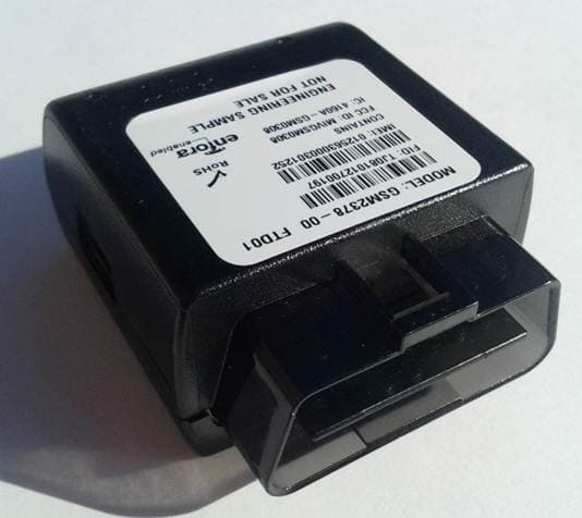
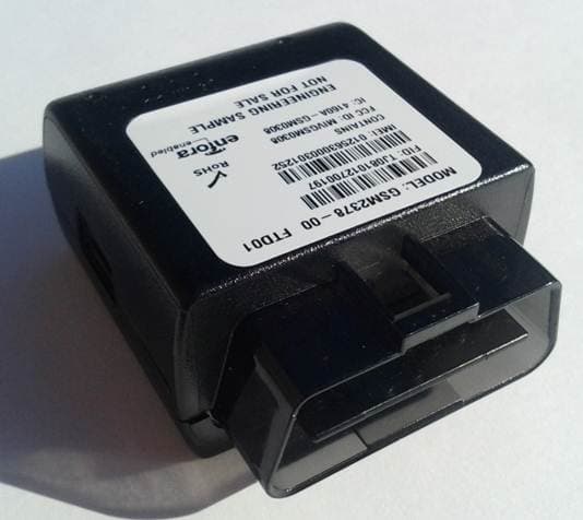
MIVGSM2378
Dec 23, 2012PCS GSM/ GPRS Licensed Transmitter
Equipment Class
PCB - PCS Licensed Transmitter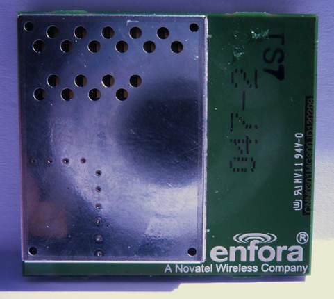
MIVCNN0301
May 10, 20121XRTT Multi-Band M2M OEM Module
Equipment Class
PCB - PCS Licensed Transmitter
MIVGSM2428
Jun 15, 2011GSM/ GPRS Personal Tracker
Equipment Class
JBP - Part 15 Class B Computing Device Peripheral
MIVGSM5218
Mar 15, 2011GSM/GPRS Asset Tracker
Equipment Class
PCB - PCS Licensed Transmitter