MIVGSM2228Mini MT Vehicle Locator
Novatel Wireless Inc.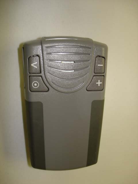
Click to zoom
Application Details
- Equipment Class
- PCB - PCS Licensed Transmitter
- Date of Grant
- Mar 13, 2007
- Application Purpose
- Original Equipment
- Date of Application
- Mar 13, 2007
- Equipment Note
- Mini MT Vehicle Locator
- Frequency Range
- 1850.20000000 - 1909.80000000
- Company
- Novatel Wireless Inc.
- Country
- Canada
Documents & Files
Document Text
Text extracted from the exhibit documents filed with the FCC. Open a document above to read the original.
Users Manual
Application Note: GSM2228AN001 Enfora Mini-MT Quick Start Guide ver 1.01 Table of Contents 1 INTRODUCTION..................................................................................................... 1 2 GETTING STARTED .............................................................................................. 2 3 OVERVIEW OF THE ENFORA MINI-MT ......................................................... 3 3.1 LED INDICATORS................................................................................................ 5 3.2 S WITCHES............................................................................................................ 6 3.2.1 Push To Call (PTC) .................................................................................... 6 3.2.2 Set Geo-Fence ............................................................................................. 6 3.2.3 User-Defined button.................................................................................... 6 3.2.4 Volume Buttons ........................................................................................... 6 3.3 I NTERCONNECTIONS............................................................................................. 7 3.3.1 USB Connection.......................................................................................... 7 3.3.2 Headphone Jack.......................................................................................... 7 3.3.3 Speaker........................................................................................................ 7 3.3.4 Microphone ................................................................................................. 7 3.3.5 SIM .............................................................................................................. 7 3.3.6 Battery......................................................................................................... 8 4 BATTERY REMOVAL / INSERTION / CHARGING ........................................ 8 4.1 R EMOVING THE BATTERY..................................................................................... 8 4.2 I NSERTING THE BATTERY..................................................................................... 8 4.3 C HARGING THE BATTERY..................................................................................... 8 5 SIM CARD INSERTION / REMOVAL ................................................................. 9 6 CONFIGURATION................................................................................................ 10 6.1 D ISPATCH NUMBER........................................................................................... 10 6.2 SMS D ESTINATION............................................................................................ 10 6.3 S ET GEO-FENCE................................................................................................. 11 6.4 U SER-DEFINED BUTTON(S) ................................................................................ 11 6.4.1 User-definable Button “” ...................................................................... 11 6.4.2 User-definable Button “>”....................................................................... 11 6.5 S ETTING THE EMERGENCY CALL NUMBER......................................................... 11 6.6 D IALING THE EMERGENCY CALL NUMBER........................................................ 12 7 SOFTWARE INSTALLATION ............................................................................ 13 7.1 M INI-MT USB COMPOSITE DEVICE – DRIVER.................................................. 14 7.2 M INI-MT USB TO UART DEVICE – DRIVER INSTALLATION............................ 18 7.3 C ONFIGURING THE PC AND VERIFYING COMMUNICATIONS................................ 21 7.3.1 Default Serial Parameters ........................................................................ 21 7.3.2 Determine which COM port to use ........................................................... 21 7.4 S TART HYPERTERMINAL................................................................................... 23 7.5 DEMO CONFIGURATION TO THE ENFORA TEST SERVER..................................... 26 7.5.1 Reset the modem to factory defaults ......................................................... 26 7.5.2 Connecting the Mini-MT to the Enfora Test Server.................................. 26 7.5.3 Configure the Modem to Access the GPRS network. ................................ 27 7.5.4 Verify Registration Status ......................................................................... 28 7.5.5 Verify GPRS Activation............................................................................. 28 7.5.6 Configure the modem to access the Enfora Server. .................................. 29 7.5.7 Verifying Server connectivity. ................................................................... 31 8 GPS OPERATION AND VERIFICATION ......................................................... 34 8.1 V ERIFICATION OF GPS LOCK............................................................................. 34 8.2 V ERIFY GPS OPERATION................................................................................... 34 8.2.1 GPS Operation from Terminal.................................................................. 34 8.2.2 GPS Operation from Enfora Demo Server ............................................... 35 9 SAFETY INFORMATION FOR WIRELESS DEVICES .................................. 36 9.1 RF E XPOSURE.................................................................................................... 36 9.2 S CIENTIFIC EVIDENCE ON RF EXPOSURE............................................................ 37 10 FCC COMPLIANCE STATEMENT ........................................................... 39 11 PRODUCT SAFETY INSTRUCTIONS ...................................................... 40 REVISION HISTORY .....................................................…
Text truncated - open the document above for the full version.
Cover Letter(s)
Enfora, Inc. 661 E. 18 th Street Plano, TX 75074-5601 (972) 633-4400 Fax (972) 633-4444 AGENCY LETTER 7 th January 2007 Telecommunication Certification Body RFI Global Services Ltd. Pavilion A Ashwood Park Basingstoke Hampshire RG23 8BG United Kingdom To whom it may concern This is to certify that Enfora, Inc. authorises RFI Global Services Ltd. to act on our behalf for the application of the GSM2228 to RFI Global Services Ltd. Telecommunication Certification Body. We certify that we are not subject to a denial of Federal benefits, that include FCC benefits, pursuant to Section 5301 of the Anti-Drug Abuse Act of 1988, 21 U.S.C. § 862 because of a conviction for possession or distribution of a controlled substance. See 47 CFR 1.2002(b) for the definition of a "party" for these purposes. Sincerely Rob Holden Manager, Compliance Engineering Enfora, Inc. 661 E. 18 th Street Plano, TX 75074 972-633-4400
Cover Letter(s)
Enfora, Inc. 661 E. 18 th Street Plano, TX 75074-5601 (972) 633-4400 Fax (972) 633-4444 7 th February 2007 REQUEST FOR CONFIDENTIALITY Telecommunication Certification Body RFI Global Services Ltd. Pavilion A Ashwood Park Basingstoke Hampshire RG23 8BG United Kingdom Subject: Certification Application FCC ID: MIVGSM2228 Enfora, Inc., requests confidentiality with regard to the following documents in the filing for equipment approval identified by FCC ID MIVGSM2228, Enfora PN GSM2228 (1) Schematic Diagrams contained in electronic files – GSM2228G800_RevD.pdf (2) Block Diagram located in electronic file – GSM2228 - Block Diagram.pdf (3) Bill Of Materials (BOM) located in electronic file – GSM2228 BOM PCA rev A.pdf (4) Schematic diagram for MLG0208 module integrated inside the GSM2228 located in electronic file – MLG0208MG802_RevC_Schematic.pdf (5) Block Diagram for MLG0208 module integrated inside the GSM2228 located in electronic file – MLG0208_BlockDiagram_2-23-06.pdf (6) Bill Of Materials (BOM) for MLG0208 module integrated inside the GSM2228 located in electronic file – MLG0208-80_BOM.xls It is the opinion of Enfora, Inc., that disclosure of this information would result in significant loss of revenue. These documents are also covered under multiple non-disclosure agreements with other companies. This information should be kept confidential for 5 years. Sincerely Rob Holden Manager, Compliance Engineering Enfora, Inc. 661 E. 18 th Street Plano, TX 75074 972-633-4400
External Photos
2 EUT PICTURES
ID Label/Location Info
* 2228520600000* 2228520600000FCC ID: * 011070000000000* M I V G S M 2 2 2 8 011070000000000
ID Label/Location Info
1.1 LABEL INSERTION Insert Barcode Label (#22) into label recess as shown in figure 25. Press label into place. Adhere CE Label (#23) to housing, positioning as shown in figure 25. Press label into place. Figure 25 22 23
Internal Photos
Figure 1: Component side of board with all shields Figure 2: Component side of board with some shields removed Figure 3: Component side of board with all shields removed Figure 4: Solder side of board with card holder Figure 5: Solder side of board with cardholder removed
Operational Description
® Mini-MT Operational Description Information in this document is proprietary to Enfora, Inc. Page 1 of 1 The Mini-MT (GSM2228) is a portable hand-held tracking device utilizing GPS for location and GSM/GPRS/SMS for communication and configuration. See Figure 1 for a block diagram of the Mini-MT. The MLG0208 is a quad-band GSM/GPRS module with an integrated GPS receiver. The GSM and GPS antennas are integrated on the PCB. The SIM card is accessed in the battery compartment. The module also controls the CALL LED for display of call and registration status. Inputs from a user are through four (4) switches for volume up, down, user defined 1, and user defined 2. Audio interfaces include an internal microphone and speaker as well as a 2.5mm Audio jack for an external headset. A mini-USB connector and USB interface for data communications, product configuration, and charging the internal battery. The internal battery is the primary power source for the Mini-MT. The battery charger requires 5VDC +/- 0.25VDC at 500mA maximum. MLG0208 SIM Holder Vibrator Motor Vol + Switch Motion Switch PTC Switch Usr 1 Switch Vol - Switch Filters Internal Mic & Speaker USB Interface Battery Charger Battery Filters USB Connector 2.5mm Audio Jack LED LEDLEDLED Microcontroller GPSGSM Usr 2 Switch CALL ONGPSBAT Figure 1 – Mini-MT Block Diagram A vibrator motor provides “silent” alerts to the user. The microcontroller performs power control to extend the battery life. It also monitors the motion switch to detect when motion occurs and when it stops. The microcontroller also monitors the PTC switch for originating a predetermined phone number or terminating an existing call. The ON, GPS, and BAT LED’s are managed by the microcontroller through serial communications to the MLG0208 module.
Operational Description
MLG0208 Circuit Description Enfora, L.P. 661 E. 18 th Street Plano, TX 75074-5601 (972) 633-4400 Fax (972) 633-4444 MLG0208 Circuit Description General Description The MLG0208 Module utilizes a Silicon Laboratories Si4210 Transceiver. This transceiver is highly integrated and provides virtually all modem functions. The module (optionally) also contains a Global Locate GL-LN22 Integrated Front-End and GL-B32-TL GPS Baseband Processor. The modem’s baseband digital processor interfaces to the GPS baseband processor via a 4-wire μWire connection. GSM/GPRS Section Si4210 Transceiver The Si4210 provide the complete RF front-end for the GSM/GPRS functions. The receiver section interfaces between the RF band-select SAW filters and the baseband subsystem. The receiver uses a digital low-IF architecture. The transmit section provides upconversion path from the baseband subsystem to the power amplifier using an offset phase-locked loop (OPLL). The transceiver uses a digitally controlled crystal (26 MHz) oscillator (DCXO) that integrates the reference oscillator and varactor functionality. D751992AZPHR Digital Baseband Processor Provides digital interfaces and control of the system. It is operated from the main oscillator from the Si4210 and also has a real time clock crystal (32.768 kHz). GPS Section A two-chip GPS solution (front-end plus baseband processor) is operated from a 26 MHz TCXO allowing for autonomous operation when the GSM section is off. The front-end is fed from the antenna input through an LNA and band-pass filter. The front-end and the GPS processor interface digitally.
Parts List/Tune Up Info
Transceiver Adjustments / Tune-Up Procedure There are no user accessible adjustments or tuning in this portable cellular transceiver. All necessary adjustments and tuning are performed during manufacture of the product. Any adjustments or tuning after service or repair are done as part of that process as special equipment is required to perform such adjustments.
RF Exposure Info
RFI GLOBAL SERVICES LTD Test Report Serial No: RFI/SARE3/RP72182JD11A Page: 30 of 50 Issue Date: 13 March 2007 Test of: Enfora L.P GSM2228 MiniMT With Personal Hands Free To: OET Bulletin 65 Supplement C (2001-01) Appendix 4. Photographs This appendix contains the following photographs: Photo Reference Number Title PHT/72182JD11A/001: SAR Configuration PHT/72182JD11A/002 Front View of EUT PHT/72182JD11A/003 Rear View of EUT PHT/72182JD11A/004 View of Personal Hands Free Kit PHT/72182JD11A/005 Internal View of EUT PHT/72182JD11A/006 Identification View PHT/72182JD11A/007 Battery View PHT/72182JD11A/008 View of Front of EUT facing Phantom PHT/72182JD11A/009 View of Rear of EUT facing Phantom PHT/72182JD11A/010 View of Rear of EUT facing Phantom with PHF PHT/72182JD11A/011 View of Front of EUT facing Phantom with PHF PHT/72182JD11A/012 Overall View of PHF PHT/72182JD11A/013 850 MHz Fluid Level PHT/72182JD11A/014 1900 MHz Fluid Level RFI GLOBAL SERVICES LTD Test Report Serial No: RFI/SARE3/RP72182JD11A Page: 31 of 50 Issue Date: 13 March 2007 Test of: Enfora L.P GSM2228 MiniMT With Personal Hands Free To: OET Bulletin 65 Supplement C (2001-01) PHT/72182JD11A/001: SAR Configuration RFI GLOBAL SERVICES LTD Test Report Serial No: RFI/SARE3/RP72182JD11A Page: 32 of 50 Issue Date: 13 March 2007 Test of: Enfora L.P GSM2228 MiniMT With Personal Hands Free To: OET Bulletin 65 Supplement C (2001-01) PHT/72182JD11A/002: Front View of EUT RFI GLOBAL SERVICES LTD Test Report Serial No: RFI/SARE3/RP72182JD11A Page: 33 of 50 Issue Date: 13 March 2007 Test of: Enfora L.P GSM2228 MiniMT With Personal Hands Free To: OET Bulletin 65 Supplement C (2001-01) PHT/72182JD11A/003: Rear View of EUT RFI GLOBAL SERVICES LTD Test Report Serial No: RFI/SARE3/RP72182JD11A Page: 34 of 50 Issue Date: 13 March 2007 Test of: Enfora L.P GSM2228 MiniMT With Personal Hands Free To: OET Bulletin 65 Supplement C (2001-01) PHT/72182JD11A/003: View of Personal Hands Free Kit RFI GLOBAL SERVICES LTD Test Report Serial No: RFI/SARE3/RP72182JD11A Page: 35 of 50 Issue Date: 13 March 2007 Test of: Enfora L.P GSM2228 MiniMT With Personal Hands Free To: OET Bulletin 65 Supplement C (2001-01) PHT/72182JD11A/004: Internal View of EUT RFI GLOBAL SERVICES LTD Test Report Serial No: RFI/SARE3/RP72182JD11A Page: 36 of 50 Issue Date: 13 March 2007 Test of: Enfora L.P GSM2228 MiniMT With Personal Hands Free To: OET Bulletin 65 Supplement C (2001-01) PHT/72182JD11A/005: View of Identification RFI GLOBAL SERVICES LTD Test Report Serial No: RFI/SARE3/RP72182JD11A Page: 37 of 50 Issue Date: 13 March 2007 Test of: Enfora L.P GSM2228 MiniMT With Personal Hands Free To: OET Bulletin 65 Supplement C (2001-01) PHT/72182JD11A/006: View of Battery RFI GLOBAL SERVICES LTD Test Report Serial No: RFI/SARE3/RP72182JD11A Page: 38 of 50 Issue Date: 13 March 2007 Test of: Enfora L.P GSM2228 MiniMT With Personal Hands Free To: OET Bulletin 65 Supplement C (2001-01) PHT/72182JD11A/007: View of Front of EUT Facing Phantom RFI GLOBAL SERVICES LTD Test Report Serial No: RFI/SARE3/RP72182JD11A Page: 39 of 50 Issue Date: 13 March 2007 Test of: Enfora L.P GSM2228 MiniMT With Personal Hands Free To: OET Bulletin 65 Supplement C (2001-01) PHT/72182JD11A/008: View of Rear of EUT Facing Phantom RFI GLOBAL SERVICES LTD Test Report Serial No: RFI/SARE3/RP72182JD11A Page: 40 of 50 Issue Date: 13 March 2007 Test of: Enfora L.P GSM2228 MiniMT With Personal Hands Free To: OET Bulletin 65 Supplement C (2001-01) PHT/72182JD11A/009: View of Front of EUT facing Phantom with PHF RFI GLOBAL SERVICES LTD Test Report Serial No: RFI/SARE3/RP72182JD11A Page: 41 of 50 Issue Date: 13 March 2007 Test of: Enfora L.P GSM2228 MiniMT With Personal Hands Free To: OET Bulletin 65 Supplement C (2001-01) PHT/72182JD11A/010: View of Rear of EUT facing Phantom with PHF RFI GLOBAL SERVICES LTD Test Report Serial No: RFI/SARE3/RP72182JD11A Page: 42 of 50 Issue Date: 13 March 2007 Test of: Enfora L.P GSM2228 MiniMT With Personal Hands Free To: OET Bulletin 65 Supplement C (2001-01) PHT/72182JD11A/011: Overall View of PHF RFI GLOBAL SERVICES LTD Test Report Serial No: RFI/SARE3/RP72182JD11A Page: 43 of 50 Issue Date: 13 March 2007 Test of: Enfora L.P GSM2228 MiniMT With Personal Hands Free To: OET Bulletin 65 Supplement C (2001-01) PHT/72182JD11A/012: 850 MHz Fluid Level RFI GLOBAL SERVICES LTD Test Report Serial No: RFI/SARE3/RP72182JD11A Page: 44 of 50 Issue Date: 13 March 2007 Test of: Enfora L.P GSM2228 MiniMT With Personal Hands Free To: OET Bulletin 65 Supplement C (2001-01) PHT/72182JD11A/013: 1900 MHz Fluid Level
RF Exposure Info
RFI GLOBAL SERVICES LTD Test Report Serial No: RFI/SARE3/RP72182JD11A Page: 45 of 50 Issue Date: 13 March 2007 Test of: Enfora L.P GSM2228 MiniMT With Personal Hands Free To: OET Bulletin 65 Supplement C (2001-01) Appendix 5. Validation of System Prior to the assessment, the systems were verified in the flat region of the phantom. A 900 MHz and 1900 MHz dipoles were used. A forward power of 250 mW was applied to the dipoles and the system was verified to a tolerance of ±5% for the 900 MHz and 1900 MHz dipoles. The applicable verification (normalised to 1 Watt). Date: 08 March 2007 Validation Dipole and Serial Number: D900V2/SN124 Simulant Frequency (MHz) Room Temperature Liquid Temperature ParametersTarget Value Measured Value Deviation (%) Limit (%) ε r 55.0 52.29 -4.93 ±5 σ 1.05 1.00 -4.59 ±5 Body 900 23.0 to 23.0 23.0 to 23.4 1g SAR 10.50 10.12 -3.62 ±5 Date: 08 March 2007 Validation Dipole and Serial Number: D1900V2/SN540 Simulant Frequency (MHz) Room Temperature Liquid Temperature ParametersTarget Value Measured Value Deviation (%) Limit (%) ε r 53.30 52.59 -1.34 ±5 σ 1.52 1.60 4.94 ±5 Body 1900 23.0 to 23.0 22.8 to 23.0 1g SAR 39.10 40.40 3.32 ±5 RFI GLOBAL SERVICES LTD Test Report Serial No: RFI/SARE3/RP72182JD11A Page: 46 of 50 Issue Date: 13 March 2007 Test of: Enfora L.P GSM2228 MiniMT With Personal Hands Free To: OET Bulletin 65 Supplement C (2001-01) Appendix 6. Simulated Tissues The body mixture consists of water and glycol. Visual inspection is made to ensure air bubbles are not trapped during the mixing process. The mixture is calibrated to obtain proper dielectric constant (permittivity) and conductivity of the tissue. Frequency Ingredient 835/850/900 MHz Body De-Ionised Water 50.75% Sugar 48.21% Salt 0.94% Kathon 0.10% Frequency Ingredient 1800/1900 MHz Body De-Ionised Water 69.79% Diglycol Butyl Ether (DGBE) 30.00% Salt 0.20% RFI GLOBAL SERVICES LTD Test Report Serial No: RFI/SARE3/RP72182JD11A Page: 47 of 50 Issue Date: 13 March 2007 Test of: Enfora L.P GSM2228 MiniMT With Personal Hands Free To: OET Bulletin 65 Supplement C (2001-01) Appendix 7. DASY4 System Details A.7.1. DASY4 SAR Measurement System RFI Global Services Ltd, SAR measurement facility utilises the Dosimetric Assessment System (DASY™) manufactured by Schmid & Partner Engineering AG (SPEAG™) of Zurich, Switzerland. The DASY4 system is comprised of the robot controller, computer, near-field probe, probe alignment sensor, and the SAM phantom containing brain or muscle equivalent material. The robot is a six-axis industrial robot performing precise movements to position the probe to the location (points) of maximum electromagnetic field (EMF). A cell controller system contains the power supply, robot controller; teach pendant (Joystick), and remote control. This is used to drive the robot motors. The Staubli robot is connected to the cell controller to allow software manipulation of the robot. The data acquisition electronics (DAE) performs signal amplification, signal multiplexing, AD-conversion, offset measurements, mechanical surface detection, collision detection etc. The DAE is connected to the Electro-optical coupler (EOC). The EOC performs the conversion from the optical into digital electric signal of the DAE and transfers data to the PC plug-in card. The DAE3 utilises a highly sensitive electrometer-grade preamplifier with auto-zeroing, a channel and gain-switching mulitplexer, a fast 16-bit AD-converter and a command decoder and control logic unit. Transmission to the PC-card is accomplished through an optical downlink for data and status information and an optical uplink for commands and clock lines. The mechanical probe-mounting device includes two different sensor systems for frontal and sidewise probe contacts. They are also used for mechanical surface detection and probe collision detection. The robot uses its own controller with a built in VME-bus computer. RFI GLOBAL SERVICES LTD Test Report Serial No: RFI/SARE3/RP72182JD11A Page: 48 of 50 Issue Date: 13 March 2007 Test of: Enfora L.P GSM2228 MiniMT With Personal Hands Free To: OET Bulletin 65 Supplement C (2001-01) A.7.2. DASY4 SAR System Specifications Robot System Positioner: Stäubli Unimation Corp. Robot Model: RX90L Repeatability: 0.025 mm No. of Axis: 6 Serial Number: F00/SD89A1/A/01 Reach: 1185 mm Payload: 3.5 kg Control Unit: CS7 Programming Language: V+ Data Acquisition Electronic (DAE) System DAE3: 394 Cell Controller PC: Dell Precision 340 Operating System: Windows 2000 Data Card: DASY4 Measurement Server Serial Number: 1080 Data Converter Features: Signal Amplifier, multiplexer, A/D converted and control logic. Software: DASY4 Software Connecting Lines: Optical downlink for data and status info. Optical uplink for commands and clock. PC Interface Card Function: 24 bit (64 MHz) DSP for real time processing Link to DAE3 16 nit A/D converter for surface detection system serial link to robot direct emergency stop output for robot. RFI GLOBAL SERVICES LTD Test Report Serial No: RFI/SARE3/RP72182JD11A Page: 49 of 50 Issue Date: 13 March 2007 Test of: Enfora L.P GSM2228 MiniMT With Personal Hands Free To: OET Bulletin 65 Supplement C (2001-01) DASY4 SAR System Specifications (Continued) E-Field Probe Model: ET3DV6 Serial No: 1528 Construction: Triangular core fibre optic detection system Frequency: 10 MHz to 3 GHz Linearity: ±0.2 dB (30 MHz to 3 GHz) Probe Length (mm): 337 Probe Diameter (mm): 12 Tip Length (mm): 10 Tip Diameter (mm): 6.8 Sensor X Offset (mm): 2.7 Sensor Y Offset (mm): 2.7 Sensor Z Offset (mm): 2.7 Phantom Phantom: SAM Phantom Shell Material: Fibreglass Thickness: 2.0 ±0.1 mm RFI GLOBAL SERVICES LTD Test Report Serial No: RFI/SARE3/RP72182JD11A Page: 50 of 50 Issue Date: 13 March 2007 Test of: Enfora L.P GSM2228 MiniMT With Personal Hands Free To: OET Bulletin 65 Supplement C (2001-01) This page has been left intentionally blank.
RF Exposure Info
RFI GLOBAL SERVICES LTD Test Report Serial No: RFI/SARE3/RP72182JD11A Page: 27 of 50 Issue Date: 13 March 2007 Test of: Enfora L.P GSM2228 MiniMT With Personal Hands Free To: OET Bulletin 65 Supplement C (2001-01) Appendix 2. Measurement Methods A.2.1. Evaluation Procedure The Specific Absorption Rate (SAR) evaluation was performed in the following manner: a) (i) The evaluation was performed in an applicable area of the phantom depending on the type of device being tested. For devices worn about the ear during normal operation, both the left and right ear positions were evaluated at the centre frequency of the band at maximum power. The side, which produced the greatest SAR, determined which side of the phantom would be used for the entire evaluation. The positioning of the head worn device relative to the phantom was dictated by the test specification identified in section 3.1 of this report. (ii) For body worn devices or devices which can be operated within 20 cm of the body, the flat section of the phantom was used. The type of device being evaluated dictated the distance of the EUT to the outer surface of the phantom flat section. b) The SAR was determined by a pre-defined procedure within the DASY4 software. The exposed region of the phantom was scanned near the inner surface with a grid spacing of 20mm x 20mm or appropriate resolution. c) A 7x7x7 matrix was performed around the greatest spatial SAR distribution found during the area scan of the applicable exposed region. SAR values were then calculated using a 3-D spline interpolation algorithm and averaged over spatial volumes of 1 and 10 grams. d) If the EUT had any appreciable drift over the course of the evaluation, then the EUT was re-evaluated. Any unusual anomalies over the course of the test also warranted a re-evaluation. RFI GLOBAL SERVICES LTD Test Report Serial No: RFI/SARE3/RP72182JD11A Page: 28 of 50 Issue Date: 13 March 2007 Test of: Enfora L.P GSM2228 MiniMT With Personal Hands Free To: OET Bulletin 65 Supplement C (2001-01) A.2.2. Specific Absorption Rate (SAR) Measurements to OET Bulletin 65 Supplement C: (2001-01) Evaluating Compliance with FCC Guidelines for Human Exposure to Radio Frequency Electromagnetic Fields SAR measurements were performed in accordance with Appendix D of the standard FCC OET Bulletin 65 Supplement C: 2001, against appropriate limits for each measurement position in accordance with the standard. The test was performed in a shielded enclosure with the temperature controlled to remain between +18.0ºC and +25.0ºC. The tissue equivalent material fluid temperature was controlled to give a maximum variation of ± 2.0ºC Prior to any SAR measurements on the EUT, system validation and material dielectric property measurements were conducted. In the absence of a detailed procedure within the specification, system validation and material dielectric property measurements were performed in accordance with Appendix C and Appendix D of FCC OET Bulletin 65 Supplement C: 2001. Following the successful system validation and material dielectric property measurements, a SAR versus time sweep shall be performed within 10 mm of the phantom inner surface. If the EUT power output is stable after three minutes then the measurement probe will perform a coarse surface level scan at each test position in order to ascertain the location of the maximum local SAR level. Once this area had been established, a 7x7x7 cube of 343 points (5 mm spacing in each axis ≈ 27g) will be centred at the area of concern. Extrapolation and interpolation will then be carried out on the 27g of tissue and the highest averaged SAR over a 10g cube determined. Once the maximum interpolated SAR measurement is complete; the coarse scan is visually assessed to check for secondary peaks within 50% of the maximum SAR level. If there are any further SAR measurements required, extra 7x7x7 cubes shall be centred on each of these extra local SAR maxima. At the end of each position test case a second time sweep shall be performed to check whether the EUT has remained stable throughout the test. RFI GLOBAL SERVICES LTD Test Report Serial No: RFI/SARE3/RP72182JD11A Page: 29 of 50 Issue Date: 13 March 2007 Test of: Enfora L.P GSM2228 MiniMT With Personal Hands Free To: OET Bulletin 65 Supplement C (2001-01) Appendix 3. SAR Distribution Scans This appendix contains SAR distribution scans which are not included in the total number of pages for this report. Scan Reference Number Title SCN/72182JD11A/001 Front of EUT Facing Phantom CH660 15mm PCS1900 SCN/72182JD11A/002 Front of EUT Facing Phantom CH660 15mm GPRS1900 SCN/72182JD11A/003 Rear of EUT Facing Phantom CH660 15mm PCS1900 SCN/72182JD11A/004 Rear of EUT Facing Phantom with PHF CH660 15mm PCS1900 SCN/72182JD11A/005 Front of EUT Facing Phantom with PHF CH660 15mm PCS1900 SCN/72182JD11A/006 Front of EUT Facing Phantom CH512 15mm PCS1900 SCN/72182JD11A/007 Front of EUT Facing Phantom CH810 15mm PCS1900 SCN/72182JD11A/008 Front of EUT Facing Phantom CH189 15mm GSM850 SCN/72182JD11A/009 Front of EUT Facing Phantom CH189 15mm GPRS850 SCN/72182JD11A/010 Rear of EUT Facing Phantom CH189 15mm GSM850 SCN/72182JD11A/011 Rear of EUT Facing Phantom with PHF CH189 15mm GSM850 SCN/72182JD11A/012 Front of EUT Facing Phantom with PHF CH189 15mm GSM850 SCN/72182JD11A/013 Front of EUT Facing Phantom CH128 15mm GSM850 SCN/72182JD11A/014 Front of EUT Facing Phantom CH251 15mm GSM850 SCN/72182JD11A/015 System Performance Check D900 08 03 07 SCN/72182JD11A/016 System Performance Check-D1900 08 03 07 Page 1 of 2 Date: 08/03/2007 72182JD11 001 Test Laboratory: RFI GLOBAL SERVICES LTD. 001 Front of EUT Facing Phantom CH660 15mm PCS1900 DUT: ENFORA L.P; Type: GSM2228 Mini MT; Serial: 2228100790200 Communication System: PCS 1900; Frequency: 1879.8 MHz;Duty Cycle: 1:8.3 Medium: 1900 MHz MSL Medium parameters used (interpolated): f = 1879.8 MHz; σ = 1.57 mho/m; ε r = 52.6; ρ = 1000 kg/m 3 Phantom section: Flat Section DASY4 Configura…
Text truncated - open the document above for the full version.
RF Exposure Info
TEST REPORT FROM RFI GLOBAL SERVICES LTD Test of: Enfora L.P GSM2228 MiniMT With Personal Hands Free To: OET Bulletin 65 Supplement C (2001-01) Test Report Serial No: RFI/SARE3/RP72182JD11A Supersedes Test Report Serial No: RFI/SARE2/RP72182JD11A This Test Report Is Issued Under The Authority Of Andrew Brown, Operations Manager: pp. Tested By: Nirav Modi pp. Checked By: Michael Derby Report Copy No: PDF01 Issue Date: 13 March 2007 Test Dates: 08 March 2007 This report is issued in Adobe Acrobat portable document format (PDF). It is only a valid copy of the report if it is being viewed in PDF format with the following security options not allowed: Changing the document, Selecting text and graphics, Adding or changing notes and form fields. Thi…
Text truncated - open the document above for the full version.
Contact Information
Applicant
Todd Gallagher(Manager, Regulatory Engineering)
Technical Contact
Test Firm
RFI Global Services Ltd.Allan Hume
Technical Specifications
| # | Rule Parts | Frequency Range | Power Output | Emission | Tolerance |
|---|---|---|---|---|---|
| 2 | 24E | 1.85 GHz - 1.91 GHz | 251.00 mW | 300KGXW | 150 ppm |
Other Applications from Novatel Wireless Inc.
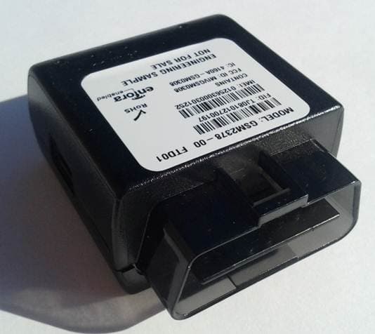
MIVRTT2211
Jan 22, 2013CDMA Licensed Transmitter
Equipment Class
PCB - PCS Licensed Transmitter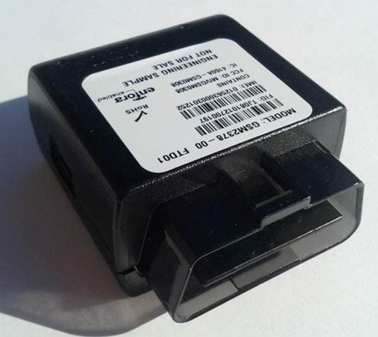
MIVGSM2378
Dec 23, 2012PCS GSM/ GPRS Licensed Transmitter
Equipment Class
PCB - PCS Licensed Transmitter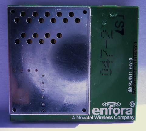
MIVCNN0301
May 10, 20121XRTT Multi-Band M2M OEM Module
Equipment Class
PCB - PCS Licensed Transmitter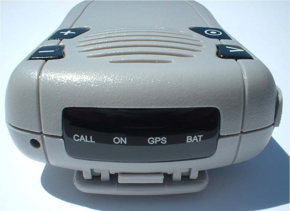
MIVGSM2428
Jun 15, 2011GSM/ GPRS Personal Tracker
Equipment Class
JBP - Part 15 Class B Computing Device Peripheral
MIVGSM5218
Mar 15, 2011GSM/GPRS Asset Tracker
Equipment Class
PCB - PCS Licensed Transmitter