MIVMLG0208GSM/GPRS/GPS Module
Novatel Wireless Inc.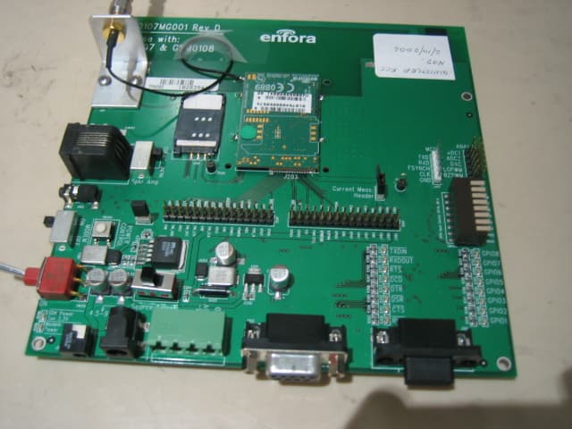
Click to zoom
Application Details
- Equipment Class
- PCB - PCS Licensed Transmitter
- Date of Grant
- Apr 10, 2006
- Application Purpose
- Original Equipment
- Date of Application
- Apr 10, 2006
- Equipment Note
- GSM/GPRS/GPS Module
- Frequency Range
- 1850.20000000 - 1909.80000000
- Company
- Novatel Wireless Inc.
- Country
- Canada
Documents & Files
Document Text
Text extracted from the exhibit documents filed with the FCC. Open a document above to read the original.
Users Manual
Enfora Enabler II-G Assisted GPS Integration Guide Version 0.1 Enfora L.P. 661 E. 18 th Street Plano Texas 75074 www enfora com Enfora Enabler II-G Assisted GPS Modem Integration Guide MLG????PB001MAN i Version Preliminary – 3/31/2006 Document Title: Enfora Enabler II-G Assisted GPS Integration Guide Version: 0.1 Date: 03/31/06 Status: PRELIMINARY Document Control ID: MLG0208PB001 General All efforts have been made to ensure the accuracy of material provided in this document at the time of release. However, the items described in this document are subject to continuous development and improvement. All specifications are subject to change without notice and do not represent a commitment on the part of Enfora L.P. Enfora L.P. will not be responsible for any loss or damages incurred related to the use of information contained in this document. This product is not intended for use in life support appliances, devices or systems where a malfunction of the product can reasonably be expected to result in personal injury. Enfora L.P. customers using, integrating, and/or selling this product for use in such applications do so at their own risk and agree to fully indemnify Enfora L.P. for any damages resulting from illegal use or resale. Copyright Complying with all applicable copyright laws is the responsibility of the user. Without limiting the rights under copyright, no part of this document may be reproduced, stored in or introduced into a retrieval system, or transmitted in any form or by any means (electronic, mechanical, photocopying, recording or otherwise), or for any purpose, without the express written permission of Enfora L.P. Enfora may have patents, patent applications, trademarks, copyrights or other intellectual property rights covering subject matter in this document. Except as expressly provided in any written license agreement from Enfora, the furnishing of this document does not give you any license to these patents, trademarks, copyrights or other intellectual property. ©2002, 2003, 2004, 2005 Enfora L.P. All rights reserved. Enabler and Spider are either registered trademarks or trademarks of Enfora L.P. in the United States. Enfora Enabler II-G Assisted GPS Modem Integration Guide MLG????PB001MAN ii Version Preliminary – 3/31/2006 1.0 Safety Precautions.................................................................................................................4 1.1 Important Safety Information ..............................................................................................4 2.0 Regulatory Compliance FCC .................................................................................................4 2.1 Integration Considerations and Installation Requirements.................................................4 2.2 Disclaimer ...........................................................................................................................7 3.0 Manual Overview ................................................................................................................... 8 3.1 Revision History.................................................................................................................. 8 3.2 Reference Documents........................................................................................................9 4.0 Introduction ..........................................................................................................................11 4.1 Product Overview .............................................................................................................11 4.2 Key Features of the Assisted GPS Module ......................................................................11 4.3 Providing Multi-Band Operation........................................................................................12 4.4 Wireless Data Application Possibilities.............................................................................12 4.5 GSM/GPRS System Overview .........................................................................................13 Assisted GPS System Overview ................................................................................................14 4.6 Summary of Features for the Enabler II-G A-GPS Module ..............................................16 5.0 Technical Specifications ......................................................................................................19 5.1 Enabler II-G A-GPS Module Block Diagram.....................................................................19 5.2 Detailed Product Specifications........................................................................................21 5.3 Operating Power...............................................................................................................23 6.0 Physical Interfaces............................................................................................................... 25 6.1 Physical Layout ................................................................................................................26 6.2 Enabler II-G A-GPS Module Mounting Reference............................................................29 6.3 Module Pin Orientation Reference ......................................................................................30 6.3 Connectors ....................................................................................................................... 30 6.4 Circuit Protection .............................................................................................................. 32 Circuit Protection ..........................................................................Error! Bookmark not defined. 6.5 Control Connector Signal Descriptions and Functions.....................................................34 6.6 Subscriber Identity Module (SIM) Carrier .........................................................................49 7.0 GSM/GPRS Modes of Op…
Text truncated - open the document above for the full version.
Cover Letter(s)
® Enfora, L.P. 661 E. 18 th Street Plano, TX 75074-5601 (972) 633-4400 Fax (972) 633-4444 February 22, 2006 REQUEST FOR CONFIDENTIALITY Enfora, L.P., requests confidentiality with regard to the following documents in the filing for equipment approval identified by FCC ID MIVMLG0208, Enfora PN MLG0208, and it’s variants MLG0207, MLG0205, MLG0204, GSM0208, GSM0207, GSM0205, and GSM0204. (1) Schematic diagrams contained in electronic file GSM0117MG800_Rev3.pdf or any subsequent revisions. (2) Block diagram located within the above schematic and in electronic file MLG0208.BlockDiagram1.Confidential.PDF. It is the opinion of Enfora, L.P., disclosure of this information would result in significant loss of revenue. These documents are also covered under multiple patents and non-disclosure agreements with other companies. This information should be kept confidential for 5 years. Scott Yarberry AVP, Product Development Enfora, L.P. 661 E. 18 th St Plano, TX 75074 972-633-4400
Cover Letter(s)
Enfora, L.P. 661 E. 18 th St. Plano, TX 75074-5601 972.633.4400 March 7, 2006 Federal Communications Commission 445 12 th Street SW Washington, DC 20554 Subject: Limited Agency Agreement Re: Enfora, L.P., MLG0208 Module We, Enfora, L.P., hereby authorized Intertek Testing Services to act as our agent for the purpose of preparing application for FCC ID number MIVMLG0208 under all applicable parts of the FCC rules and regulations. The effective date of this limited agency agreement is March 7, 2006. The limited agency agreement expires on March 7, 2007 unless sooner terminated or extended by written notice to Intertek Testing Services and the Federal Communications Commission. This is to advise that we are in full compliance with the Anti-Drug Abuse Act. The applicant is not subject to a denial of federal benefits pursuant to Section 5301 of the Anti-Drug Act of 1988, 21 U.S.C. 862, and no party to the application is subject to a denial of federal benefits pursuant to that section. If you have any questions or comments, please do not hesitate to contact me. Sincerely, John H. Denton
External Photos
2 EUT PICTURES
Internal Photos
Figure 1: Component side of board with all shields Figure 2: Component side of board with some shields removed Figure 3: Component side of board with all shields removed Figure 4: Solder side of board with card holder Figure 5: Solder side of board with cardholder removed
Operational Description
MLG0208 Circuit Description Enfora, L.P. 661 E. 18 th Street Plano, TX 75074-5601 (972) 633-4400 Fax (972) 633-4444 MLG0208 Circuit Description General Description The MLG0208 Module utilizes a Silicon Laboratories Si4210 Transceiver. This transceiver is highly integrated and provides virtually all modem functions. The module (optionally) also contains a Global Locate GL-LN22 Integrated Front-End and GL-B32-TL GPS Baseband Processor. The modem’s baseband digital processor interfaces to the GPS baseband processor via a 4-wire μWire connection. GSM/GPRS Section Si4210 Transceiver The Si4210 provide the complete RF front-end for the GSM/GPRS functions. The receiver section interfaces between the RF band-select SAW filters and the baseband subsystem. The receiver uses a digital low-IF architecture. The transmit section provides upconversion path from the baseband subsystem to the power amplifier using an offset phase-locked loop (OPLL). The transceiver uses a digitally controlled crystal (26 MHz) oscillator (DCXO) that integrates the reference oscillator and varactor functionality. D751992AZPHR Digital Baseband Processor Provides digital interfaces and control of the system. It is operated from the main oscillator from the Si4210 and also has a real time clock crystal (32.768 kHz). GPS Section A two-chip GPS solution (front-end plus baseband processor) is operated from a 26 MHz TCXO allowing for autonomous operation when the GSM section is off. The front-end is fed from the antenna input through an LNA and band-pass filter. The front-end and the GPS processor interface digitally.
Parts List/Tune Up Info
® Enfora, L.P. 661 E. 18 th Street Plano, TX 75074-5601 (972) 633-4400 Fax (972) 633-4444 February 22, 2006 Tune-Up Procedure Description for MLG0208 Power Adjustments The RF power output of the modem is preset during the manufacturing process via software- controlled adjustment of calibration parameters referenced to a base-station simulator. Under normal operation, the RF output power is maintained via an ALC circuit. Neither the integrator nor end-user has access to the calibration/power adjustment of the device. Frequency Adjustments Under normal operation, the transmitter uses a frequency synthesizer synchronized a base- station clock, thus there are no frequency alignments that must be made. Scott Yarberry AVP, Product Development Enfora, L.P. 661 E. 18 th St Plano, TX 75074 972-633-4400
Test Report
This report is for the exclusive use of Intertek's Client and is provided pursuant to the agreement between Intertek and its Client. Intertek’s responsibility and liability are limited to the terms and conditions of the agreement. Intertek assumes no liability to any party, other than to the Client in accordance with the agreement, for any loss, expense or damage occasioned by the use of this report. Only the Client is authorized to copy or distribute this report and then only in its entirety. Any use of the Intertek name or one of its marks for the sale or advertisement of the tested material, product or service must first be approved in writing by Intertek. The observations and test results in this report are relevant only to the sample tested. This report by itself does not imply that the material, product, or service is or has ever been under an Intertek certification program. Report issued on: 03/03/06 Report revised on: 04/03/06 TEST REPORT Report Number: 3091531DAL-001 Project Number: 3091531 Evaluation of the Wireless MODEM Model Number: MLG0208 FCC ID: MIVMLG0208 FCC Part 2 FCC Part 15 FCC Part 22 Subpart H FCC Part 24 Subpart E For Enfora Test Performed by: Test Authorized by: Intertek 420 N Dorothy Drive Richardson, TX 75081 Enfora 661 E. 18 th Street Plano, TX 75074 Prepared By:_______________________________Date:04/04/06 Sudesh Kamble, EMC Team Leader Approved By:______________________________Date:_4-4-2006 ___ Roland Gubisch, Chief Engineer, EMC and Telecom Intertek 420 N Dorothy Drive, Richardson, TX 75081 420 N Dorothy Drive, Richardson, TX 75081 Evaluation For:Enfora FCC ID: MIVGSM0208 Model No: MLG0208 Report Number: 3091531DAL-001 Page 2 of 41 FCC Part 2, 15, and 24 Evaluation TABLE OF CONTENTS 1 JOB DESCRIPTION ............................................................................................................................... 4 1.1 GENERAL INFORMATION.................................................................................................................. 4 1.1.1 System Support Equipment........................................................................................................... 5 1.1.2 Cables associated with EUT ........................................................................................................ 5 1.1.3 System Block Diagram ................................................................................................................. 5 1.1.4 Mode(s) of operation.................................................................................................................... 5 2 EXECUTIVE SUMMARY...................................................................................................................... 6 2.1 REPORT REVISION HISTORY: ............................................................................................................. 6 3 TEST FACILITY..................................................................................................................................... 7 3.1 TEST EQUIPMENT USED.................................................................................................................... 8 4 CONDUCTED RF POWER ................................................................................................................... 9 4.1 TEST PROCEDURE............................................................................................................................. 9 4.2 TEST RESULTS.................................................................................................................................. 9 5 RADIATED RF POWER ...................................................................................................................... 10 5.1 TEST LIMITS.................................................................................................................................... 10 5.2 TEST PROCEDURE........................................................................................................................... 10 5.3 TEST RESULTS................................................................................................................................11 6 MAXIMUM PERMISSIBLE EXPOSURE (MPE) CALCULATIONS ........................................... 12 6.1 TEST LIMITS.................................................................................................................................... 12 6.2 TEST PROCEDURE........................................................................................................................... 12 6.3 TEST RESULTS................................................................................................................................12 7 EMISSION LIMITATIONS, OCCUPIED BANDWIDTH ............................................................... 13 7.1 TEST LIMITS.................................................................................................................................... 13 7.2 TEST PROCEDURE........................................................................................................................... 13 7.3 TEST RESULTS................................................................................................................................13 8 OUT OF BAND EMISSION AT ANTENNA TERMINALS............................................................. 20 8.1 TEST LIMITS.................................................................................................................................... 20 8.2 TEST PROCEDURE........................................................................................................................... 20 8.3 TEST RESULTS................................................................................................................................21 9 FIELD STRENGTH OF SPURIOUS RADIATION .......................................................................... 29 9.1 TEST LIMITS................................…
Text truncated - open the document above for the full version.
Contact Information
Applicant
Todd Gallagher(Manager, Regulatory Engineering)
Technical Contact
Enfora L.P.Scott Yarberry
[email protected]972-633-4400
661 E. 18th Street · Plano, Texas · United States
Non-Technical Contact
Enfora L.P.Scott Yarberry
[email protected]972-633-4400
Test Firm
Intertek Testing Services NA, Inc.Sudesh Kamble
Technical Specifications
| # | Rule Parts | Frequency Range | Power Output | Emission | Tolerance |
|---|---|---|---|---|---|
| 2 | 24E | 1.85 GHz - 1.91 GHz | 625.00 mW | 300KG7W | 150 ppm |
Other Applications from Novatel Wireless Inc.
MIVRTT2211
Jan 22, 2013CDMA Licensed Transmitter
Equipment Class
PCB - PCS Licensed Transmitter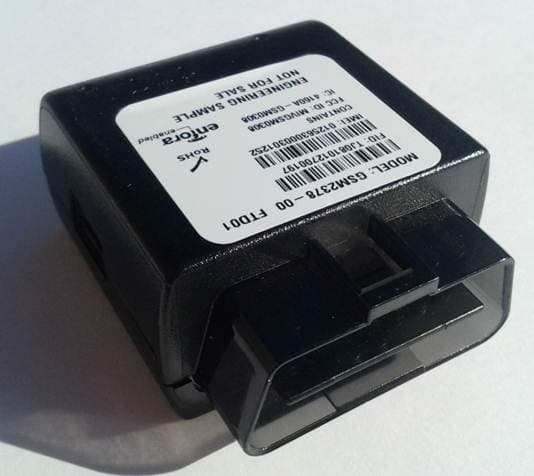
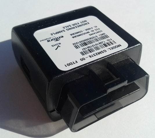
MIVGSM2378
Dec 23, 2012PCS GSM/ GPRS Licensed Transmitter
Equipment Class
PCB - PCS Licensed Transmitter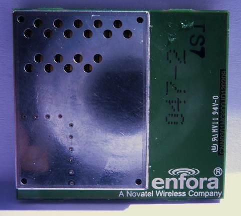
MIVCNN0301
May 10, 20121XRTT Multi-Band M2M OEM Module
Equipment Class
PCB - PCS Licensed Transmitter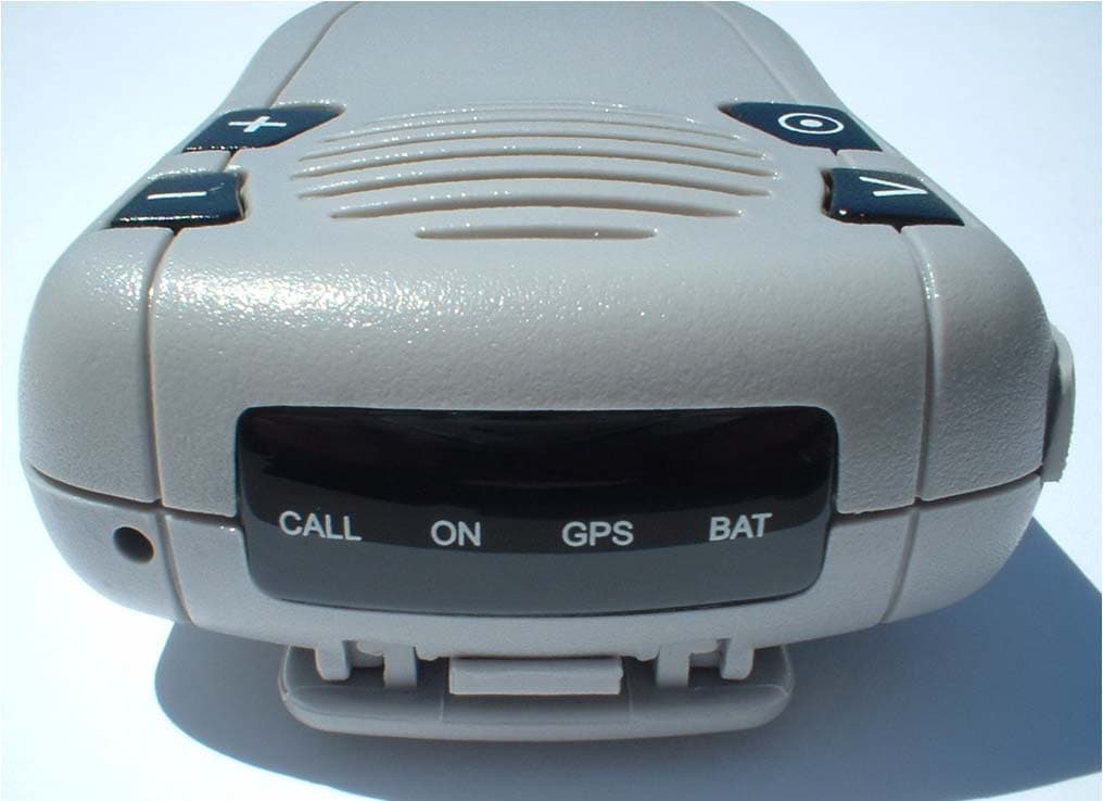
MIVGSM2428
Jun 15, 2011GSM/ GPRS Personal Tracker
Equipment Class
JBP - Part 15 Class B Computing Device Peripheral
MIVGSM5218
Mar 15, 2011GSM/GPRS Asset Tracker
Equipment Class
PCB - PCS Licensed Transmitter