MIVWG0001ASpider 4 CDPD Modem
Novatel Wireless Inc.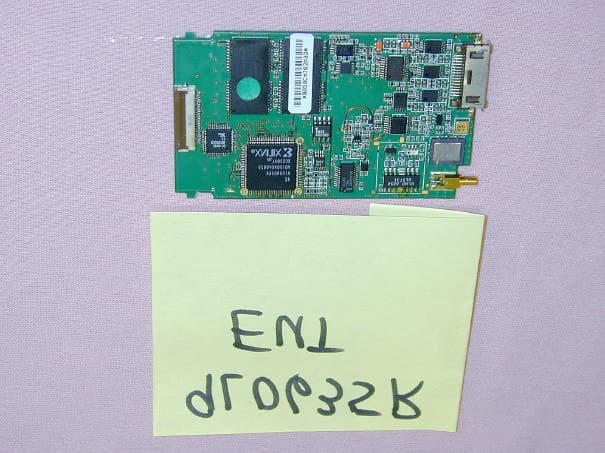
Click to zoom
Application Details
- Equipment Class
- TNB - Licensed Non-Broadcast Station Transmitter
- Date of Grant
- May 11, 2000
- Application Purpose
- Original Equipment
- Date of Application
- Apr 10, 2000
- Equipment Note
- Spider 4 CDPD Modem
- Frequency Range
- 824.00000000 - 849.00000000
- Company
- Novatel Wireless Inc.
- Country
- Canada
Documents & Files
Document Text
Text extracted from the exhibit documents filed with the FCC. Open a document above to read the original.
Users Manual
Introduction About the Spider 4 The Spider 4 is a 4-watt modem with optional Global Positioning Satellite (GPS) capabilities. You can remotely access mission critical files and applications on your network, designed for devices operating Windows 95, 98, NT or 2000. It provides wide area network connectivity over wireless IP services (CDPD). The Spider 4 is illustrated in Figure 1 (Front View) and Figure 2 (Back View). About This Manual This manual describes how to install and use the Spider 4. To take full advantage of your Spider 4, please read all the instructions in this manual. Contents of This Package Your Spider 4 package from Nextcell includes one of the following items: • Spider 4 • Mounting screws (4) • One 20-foot power harness • One 22-foot serial cable • One user’s manual • One Spider Installation Guide (CD-ROM) GPS OptionCDP-0114-04-002 • GPS receiver embedded in Spider 4 • One 22-foot serial cable • One of the GPS antenna option Available Options The following optional antennas are available for purchase through your authorized Nextcell agent: Part #ANT-9701-05-001 Cellular roof/trunk mount antenna with thru-hole mounting kit and installation instructions Part #ANT-9704-05-001 GPS Antenna with thru-hole mounting kit and installation instructions Part #ANT-9705-05-001 GPS Antenna magnetic mounting kit with installation instructions System Requirements Serial port – One serial port is required for Spider-4. A second serial port is required for GPS option. Spider Modem Manager Refer to installation menu for Spider Installation Guide. Upgrade Information If your current system does not meet these requirements, please contact Nextcell 661 E. 18th Street Plano, Texas 75074 USA Or contact us at our Website: http://www.nextcell.com Installation Installing the Spider 4 To install the Spider 4 into a vehicle, follow these steps: 1.Choose a convenient location in the vehicle, either in the interior or the trunk. 2.Place the Spider 4 in position and mark the location of the mounting holes. 3.Using your marks as a guide, drill the holes using a 1/16-inch drill bit. 4.Align the Spider 4 with the holes that you drilled and secure it using the mounting screws provided. Installing Cables Turn off the computer, Spider 4 and vehicle when installing the Spider 4, antennas or cables. Do not create tight loops, sharp bends or crimps in the cables. Use proper termination on all power cables. All cables should be attached to the vehicle and equipment in such a way as to reduce stress or wear caused by vibrations generated by moving vehicles. Connecting the Power Supply It is extremely important that you connect to an auxiliary power circuit that becomes active ONLY when the ignition switch is turned ON (e.g., the car radio). There are numerous after-market products available that provide automatic on/off switching, low voltage disconnects, reverse polarity protection and high voltage protection for your Spider 4. Consult your automobile manufacturer, automotive parts or consumer electronic stores for more information on these products. Using the Power Harness provided, connect the Spider 4 to your vehicle’s power supply exactly as follows: •Connect the black wire to chassis ground. •Connect the white wire to auxiliary power. •Connect the red wire directly to the 12 volt supply of the battery. The connection must be capable of supplying up to 4 amps at 12 volts. •Connect the Power Harness to the Spider 4 connector labeled Power. If you have installed the Spider 4 properly, the LED on the front of the Spider 4 illuminates only when you turn the ignition ON. Installing the Serial Modem Cable Attach one end of the Serial cable to the computer’s COM port and the other to the Spider 4’s Serial Modem plug. The Serial Modem plug on the Spider 4 is illustrated in Figure 3. Antenna Installation Your Spider 4 package may not include an antenna. You have the flexibility to purchase an antenna from Nextcell or choose an antenna that meets your individual needs. Be sure that you select an antenna with the following features: •The antenna is specified to operate in the cellular band (824 – 894 MHz) with 3 dB gain. •The antenna has a 50 ohm cable terminated with a TNC style connector. Locate and install the antenna on the vehicle according to the manufacturer’s instructions. Attach the TNC connector to the Spider 4 terminal labeled Antenna. The antenna must be installed a minimum of 0.5 meters (20 inches) from car occupants and pedestrians. Do not attempt to operate the Spider 4 without an antenna connected. Severe damage to the Spider 4 and/or computer may result. Installing the Antenna Manufacturer’s instructions for installing the Spider 4 Antenna are included with the antenna kit (Part #CDP-1300-04-003 or #ANT-9701-05-001). Follow those directions very carefully in order to avoid damaging the Spider 4 and/or computer. The Antenna terminal on the Spider 4 is illustrated in Figure 4. Figure 4: Antenna Terminal on the Spider 4 Getting Started Spider Modem Manager Main Window Refer to Spider Installation Guide and Spider Users Manual Optional GPS Antenna and Receiver The Nextcell Spider 4 with GPS provides data to your computer in the NMEA or SiRF binary format. The factory-default for the Spider 4 is the NMEA format. NMEA Format To use this GPS Receiver in the NMEA format, purchase and install mapping software that adheres to the industry-standard NMEA format on your computer. SiRF Format To use this GPS Receiver in the SiRF binary format, download and install Axion Navigation, Inc.’s software, Conductor software, from their Website at http://www.axiomnav.com. About the GPS Receiver The Receiver powers the preamplifier in the GPS Antenna (Active-style) by applying a 5 volt DC bias to the center conductor of the RF input to the GPS Receiver. We strongly suggest you install the Antenna supplied by Nextcell, Inc. If you must use a Passive-style GPS Antenna, please verify that it has a DC block installed in order to…
Text truncated - open the document above for the full version.
Users Manual
DRAFT SPIDER-4 USER'S MANUAL Revised 28 Apr 2000 1 INTRODUCTION About the Spider 4 The Spider 4 is a 4-watt modem with optional Global Positioning Satellite (GPS) capabilities. You can remotely access mission critical files and applications on your network, designed for devices operating Windows 95, 98, NT or 2000. It provides wide area network connectivity over wireless IP services (CDPD). The Spider 4 is illustrated in Figure 1 (Front View) and Figure 2 (Back View). Figure 1. Front View Figure 2. Back View About This Manual This manual describes how to install and use the Spider 4. To take full advantage of your Spider 4, please read all the instructions in this manual. Contents of This Package Your Spider 4 package from Nextcell includes one of the following items: • Spider 4 • Mounting screws (4) • One 20-foot power harness • One 22-foot serial cable • One user’s manual • One Spider Installation Guide (CD-ROM) GPS Option CDP-0114-04-002 •GPS receiver embedded in Spider • One 22-foot serial cable • One of the GPS antenna option Available Options The following optional antennas are available for purchase through your authorized Nextcell agent: • Part #ANT-9701-05-001 Cellular roof/trunk mount antenna with thru-hole mounting kit and installation instructions • Part #ANT-9704-05-001 GPS Antenna with thru-hole mounting kit and installation instructions • Part #ANT-9705-05-001 GPS Antenna magnetic mounting kit with installation instructions DRAFT SPIDER-4 USER'S MANUAL Revised 28 Apr 2000 2 System Requirements • Serial port – One serial port is required for Spider-4. A second serial port is required for GPS option. • Spider Modem Manager • Refer to installation menu for Spider Installation Guide. Upgrade Information If your current system does not meet these requirements, please contact Nextcell 661 E. 18th Street Plano, Texas 75074 USA Or, contact us at our Website: http://www.nextcell.com INSTALLATION Installing the Spider 4 To install the Spider 4 into a vehicle, follow these steps: 1. Choose a convenient location in the vehicle, either in the interior or the trunk. 2. Place the Spider 4 in position and mark the location of the mounting holes. 3. Using your marks as a guide, drill the holes using a 1/16-inch drill bit. 4. Align the Spider 4 with the holes that you drilled and secure it using the mounting screws provided. Installing Cables Install cables in the following manner: 1. Turn off the computer, Spider 4 and vehicle when installing the Spider 4, antennas or cables. 2. Do not create tight loops, sharp bends or crimps in the cables. 3. Use proper termination on all power cables. 4. All cables should be attached to the vehicle and equipment in such a way as to reduce stress or wear caused by vibrations generated by moving vehicles. Terminating Power Cables All cables should be attached to the vehicle and equipment in such a way as to reduce stress or wear caused by vibrations generated by moving vehicles. Connecting the Power Supply CAUTION Connect to an auxiliary power circuit that becomes active ONLY when the ignition switch is turned on. It is extremely important that you connect to an auxiliary power circuit that becomes active ONLY when the ignition switch is turned ON (e.g., the car radio). There are numerous after- DRAFT SPIDER-4 USER'S MANUAL Revised 28 Apr 2000 3 market products available that provide automatic on/off switching, low voltage disconnects, reverse polarity protection and high voltage protection for your Spider 4. Consult your automobile manufacturer, automotive parts or consumer electronic stores for more information on these products. Using the Power Harness provided, connect the Spider 4 to your vehicle’s power supply exactly as follows: •Connect the black wire to chassis ground. •Connect the white wire to auxiliary power. •Connect the red wire directly to the 12 volt supply of the battery. The connection must be capable of supplying up to 4 amps at 12 volts. •Connect the Power Harness to the Spider 4 connector labeled Power. If you have installed the Spider 4 properly, the LED on the front of the Spider 4 illuminates only when you turn the ignition ON. Installing the Serial Modem Cable Attach one end of the Serial cable to the computer’s COM port and the other to the Spider 4’s Serial Modem plug. The Serial Modem plug on the Spider 4 is illustrated in Figure 3. Figure 3. Serial Modem plug ANTENNA INSTALLATION Your Spider 4 package may not include an antenna. You have the flexibility to purchase an antenna from Nextcell or choose an antenna that has the same specifications and construction as the antenna provided by Nextcell. Select an antenna with the following features: •The antenna is specified to operate in the cellular band (824 – 894 MHz) with 3 dBd gain. •The antenna has a 50 ohm cable terminated with a TNC style connector. Locate and install the antenna on the vehicle according to the manufacturer’s instructions. CAUTION In order to comply with FCC RF Maximum Permissible Exposure Limits (MPEL), the following configuration must be followed. 1.The antenna must be installed a minimum of 0.5 meters (20 inches) from car occupants and pedestrians. 2.The rf cable between the Spider 4 and the antenna must have at least 1 dB of insertion loss. 3. If an antenna other than the one provided by Nextcell is used, the antenna used must have the same electrical specifications and physical construction as the antenna provided by Nextcell. DRAFT SPIDER-4 USER'S MANUAL Revised 28 Apr 2000 4 Compliance with FCC RF exposure limits was evaluated with the above configuration. Other configurations that have not been tested may not comply with FCC RF exposure limits and should be avoided. CAUTION Do not attempt to operate the Spider 4 without an antenna connected. Severe damage to the Spider 4 and/or computer may result. Installing the Antenna Manufacturer’s instructions for installing the Spider 4 Antenna are included with the antenna kit (Part #ANT-9701-05-001). Follow th…
Text truncated - open the document above for the full version.
Attestation Statements
Federal Communications Commission 7435 Oakland Mills Road Columbia, MD 21046 USA SUBJECT:AUTHORITY TO ACT AS AGENT TO THE FEDERAL COMMUNICATIONS COMMISSION On our behalf, I appoint KTL Dallas, Inc. to act as agent in the preparation of this application for equipment authorization to the Federal Communications Commission (FCC). I certify that submitted Exhibits properly describe the device or system for which equipment authorization is sought. I also certify that each unit manufactured, imported or marketed, as defined in the Commission’s regulations will have affixed to it a label identical to that submitted for approval with this application. APPLICANT ANTI-DRUG ABUSE CERTIFICATION: In signing this letter, Nextcell, Inc. certifies that, as a corporation, no party to the application is subject to a denial of Federal benefits, that includes FCC benefits, pursuant to Section 5301 of the Anti-Drug Abuse Act of 1988, 21 U.S.C. 853(a). For the definition of a “party” for these purposes, see 47 CFR 1.2002(b). Dated this 31st Day of March 2000 Agency agreement expiration date: Open By:Durward E. Rutledge, P.E. Title:Vice President, Product Integrity Telephone:(972) 633-4441 Applicant:Nextcell, Inc.
ID Label/Location Info
FCC ID: MIVWG0001A Canada: XXXXXXXXXXX Text silk screened on chassis
Operational Description
Range of operating power levels and a description of the means by which the RF power is varied The Spider 4 is a Class 1 CDPD MES (Mobile End Station) as defined by the CDPD Forum (CDPD System Specification - Release 1.1) Class 1 CDPD systems have ten defined nominal power levels. For each discrete power level there is an allowable range of power about the nominal value of +2 dB to - 4 dB. Class 1 CDPD power levels (0,1,2,3,4,5,6,7,8,9,10) correspond in order with the following powers (+6,+2,-2,-6,- 10,-14,-18,-22,-22,-22,-22) dBw or expressed again as Watts (4, 1.58, 0.63, 0.25, 0.1, 0.04, 0.016, 0.0063) Watts The modems transmit power levels are controlled directly by the AMPS base station. The base station makes a determination of the appropriate power level for modem transmission based on its RSSI (Received Signal Strength Indication). During normal modem operation there are no means provided by which the end user may modify transmit power levels. Special pass-worded software debug modes will allow the power level to be changed but these protected modes are not available to end users. Maximum RF power rating The maximum RF power that the Nextcell Spider 4 modem (a class 1 CDPD mobile end station) may transmit is defined by the CDPD Forum (CDPD System Specification - Release 1.1) Class 1 systems are specified to have a nominal level of 6 dBw and are restricted to a transmission power of no more than 8 dBw. Stated in Watts the maximum power allowed is 6.3 Watts. The Spider 4 is designed to transmit at a nominal level of 4 watts during "full power transmit". By design transmit amplifier saturation will prevent transmission at any higher power. Closed loop automatic gain circuitry within the Spider 4 constantly monitors and adjusts the control voltage of the PA. The AGC circuitry will prevent will sense excessive transmit power and reduce the output power if for any reason. The dc voltages applied to and dc currents into the elements of the final rf amp for normal operation over the specified power range or at specific power level 11.45 Vdc is applied to the final RF power Amp, the dc current range from 30 mA to 1 A over 0.0063 watts to 4 watts. Description of all circuitry and devices provided for determining and stabilizing frequency, for suppression of spurious radiation, for limiting modulation, and for limiting power. The Frequency determination and Spurious Radiation suppression are performed by the Spider Modem as describe below and please refer to Answer 8 for limiting power. Frequency determination. All local oscillators, clocks and timing signals are derived from one crystal source. This source is a 15.36 MHz temperature compensated crystal oscillator which is designed for cellular applications and purchased to a specification indicating compliance to frequency tolerance requirements for this class of equipment. There are no other free running oscillators, clock sources, or timing generating devices in the modem. This one reference is used for all frequency generating circuits. The final transmitted signal is generated from the mixing of a transmit LO and the main LO. The transmit LO is a 180 MHz VCO phase locked to the 15.36 MHz reference oscillator with a reference frequency of 60 KHz when in CDPD mode. The main LO is also phase locked to the reference oscillator with a 30 KHz phase reference clock. It will be tuned from 914.01 MHz to 938.57 MHz with a step size of 30 KHz. The receiver uses the main LO and a receive LO. The receive LO is at 90 MHz and is also locked to the reference oscillator and uses a 24 KHz phase reference clock. All three phase lock loop circuits have lock indicator signals that verifies proper operation of the circuitry. This signal is provided to the modem processor and is monitored during normal operation. The transmitter will not be enabled unless all phase lock loops are indicating that they all properly locked to their assigned frequency. The frequency stability of the reference oscillator is specified to a temperature of -30 to + 70 degrees C. The modem is specified with an operational temperature range of 0 to +45 degrees C. An internal temperature sensor is included in the modem to detect temperature conditions outside 0 to + 70 degrees C. When detecting a temperature range outside this range the modem processor will not allow transmissions to occur. Spurious Radiation suppression. A metal shield is required around the entire modem to suppress spurious emissions. The modem housing provides this function. In order to ensure the top and bottom cover are connected electrically, the grounding tabs on the 15-pin connector must be bent at roughly 45 degree angles at the time of assembly. All test data was taken with the grounding tabs utilized. Description of the digital modulation technique, a detailed description of the modulation system to be used, including the response characteristics (frequency, phase, and amplitude) of any filters to be used The transmitter covers the band of 824.010 MHz to 848.970 MHz and is tuned in 30 KHz steps. In CDPD mode, the modulation type is a Gaussian Minimum Shift Keying (GMSK) with BT= .5. The data rate is fixed at 19.2 Kbps. Modulation of a carrier is done at the Transmit LO (180 MHz) with an I and Q modulator in CDPD mode. The baseband I and Q waveforms, with all of the filter characteristics required to meet the emissions mask, have been described digitally and stored permanently in non-volatile memory. A microcontroller is used to translate the data stream to be transmitted into the appropriate baseband signals. The digital signals are generated at 16 times over sampling, and the analog signals are recreated with an 8-bit digital-to-analog conversion process. This modulation technique requires no tuning or adjustments to meet the emissions mask. Also, because the data is encoded with a pseudo random sequence, the modulation mask is constant and independent of the data being sent. The output spectrum is constant…
Text truncated - open the document above for the full version.
RF Exposure Info
KTL Ottawa Safety - EMI - Telecom - ISO Guide 25 Master: KTLmpefccp1 Date: June 4, 1998 ENGINEERING TEST REPORT ON: "INET 'SPIDER B3' 4 WATT BOOSTER" IN ACCORDANCE WITH: MPE REQUIREMENTS OF THE FCC PART 1 PROJECT NO.: 8R00203.1 TESTED FOR: INET INC. 1255 W. 15 TH STREET PLANO, TEXAS 75075-7270 TESTED BY: KTL OTTAWA INC. 3325 RIVER ROAD, R.R. 5 OTTAWA, ONTARIO K1V 1H2 JUNE 1998 This document contains 21 pages including this one. KTL Ottawa Inc. authorizes the above named company to reproduce this report provided it is reproduced in its entirety and for use by the company’s employees only. Any use which a third party makes of this report, or any reliance on or decisions to be made based on it, are the responsibility of such third parties. KTL Ottawa Inc. accepts no responsibility for damages, if any, suffered by any third party as a result of decisions made or actions based on this report. This report applies only to the items tested. KTL OttawaMPE REQUIREMENTS OF THE FCC PART 1 PROJECT NO.: 8R00203.1 EQUIPMENT: INET "Spider B3"4 Watt Booster Page 2 of 21 TABLE OF CONTENTS Section 1. Summary of Test Results Test Rationale Section 2. Equipment Under Test (E.U.T.) Description of E.U.T. Modifications Incorporated in E.U.T. Theory of Operation Justification Exercise Program Section 3. Equipment Configuration Equipment Configuration List Inter-connection Cables Configuration of the Equipment Under Test (E.U.T.) Block Diagram Section 4. Test Configuration A Test #1 Test #2 Test #3 Measurements Inside Vehicle with Antenna Mounted In Center Of Roof Test #4 Measurements Inside Vehicle with Antenna Mounted At Rear Section 5. Configuration B Test #1 Test #2 Test #3 Test #4 Test #5 Measurements Inside Vehicle Test #6 Measurements Behind Panel Van Section 6. Test Equipment Section 7. Photos KTL OttawaMPE REQUIREMENTS OF THE FCC PART 1 PROJECT NO.: 8R00203.1 EQUIPMENT: INET "Spider B3"4 Watt Booster Page 3 of 21 Section 1.Summary of Test Results Test Rationale This testing was patterned after testing done in FCC/OET document ASD-9601, “Measurements of Environmental Electromagnetic Fields at Amateur Radio Stations” and OET Bulletin 65 Edition 97-01, “Evaluating Compliance with FCC Guidelines for Human Exposure to Radiofrequency Electromagnetic Fields. Emissions were measured using a standard Roberts type dipole antenna tuned to cellular channel 383. The measured field strength was then converted to Power Density by the following relation: S = E 2 /3770 where S = power density (mW/cm 2 ) E = electric field strength (V/m) This equation is given on page 9 of OET Bulletin 65. Measurements were made with the E.U.T. feeding a magnetic roof mount antenna as prescribed by the manufacturer. Measurements were made with the system installed on two different vehicles; a standard passenger vehicle and a pickup truck. Field strengths were measured at distances from 0.5 to 3 metres. The receive antenna height was varied from 1 - 3 metres to determine maximum emission levels. Measurements were also performed with the vehicle parked adjacent to a panel van in order to investigate “hot spots” that may be caused by reflection from a nearby metallic object. Conclusion In the configuration tested, the E.U.T. complies with the requirements of MPE Requirements of the FCC Part 1. THIS TEST REPORT RELATES ONLY TO THE ITEM(S) TESTED. THE FOLLOWING DEVIATIONS FROM, ADDITIONS TO, OR EXCLUSIONS FROM THE TEST SPECIFICATION HAVE BEEN MADE. None Test Performed By: ________________________________Date: ___________________ Tom Tidwell, Senior Technologist Approved By: __________________________________Date: ___________________ W. Waterhouse, RF Engineering Lab Manager KTL OttawaMPE REQUIREMENTS OF THE FCC PART 1 PROJECT NO.: 8R00203.1 EQUIPMENT: INET "Spider B3"4 Watt Booster Page 4 of 21 Section 2. Equipment Under Test (E.U.T.) Manufacturer:INET Inc. Model No.:"Spider B3" Serial No.:None Production UnitPre-Production Unit Description of E.U.T. The E.U.T. is a 4 watt booster for connection to the Spider PCMCIA CDPD modem. Modifications Incorporated in E.U.T. The EUT has not been modified from what is described by the brand name and unique type identification stated above. KTL OttawaMPE REQUIREMENTS OF THE FCC PART 1 PROJECT NO.: 8R00203.1 EQUIPMENT: INET "Spider B3"4 Watt Booster Page 5 of 21 Theory Of Operation The E.U.T. connects to the FCC approved "Spider" CDPD modem; (FCC ID: MIVWG9501A), to boost the Class III 0.6 watt modem power level to a 4 watt Class I output level. The booster uses duplexers at the input and output to split the Tx and Rx paths. The Tx path has three stages: Electronic Attenuator, PA Driver and PA. The Rx path has four stages: Preamp, SAW Filter, LNA and Electronic Attenuator. Block Diagram DuplexerDuplexer PA LNA Modem Connection Antenna Connection KTL OttawaMPE REQUIREMENTS OF THE FCC PART 1 PROJECT NO.: 8R00203.1 EQUIPMENT: INET "Spider B3"4 Watt Booster Page 6 of 21 Justification The E.U.T. was configured for testing as per typical installation. Position and bundling of cables were investigated to establish maximum amplitude of emissions. The following combinations were investigated to establish worst case configuration: (1) E.U.T. transmitting at 4 watts. (2) Antenna mounted in center of vehicle roof. (3) Antenna mounted at back of vehicle roof. (4) Vehicle parked adjacent to vertical metal surface. Exercise Program The E.U.T. exercise program used during testing was designed to exercise the various system components in a manner similar to typical use. Exercise Mode: Not Applicable. KTL OttawaMPE REQUIREMENTS OF THE FCC PART 1 PROJECT NO.: 8R00203.1 EQUIPMENT: INET "Spider B3"4 Watt Booster Page 7 of 21 Section 3.Equipment Configuration Equipment Configuration List: ItemDescriptionModel No.Serial.Rev. (A)Toshiba Satellite Notebook PCPA1196UV10563296-1 (B)PCMCIA ModemSpiderNone (C)Radio Shack Cellular AntennaNoneNone (D)4 Watt BoosterSpider B3None Inter-connection Cables: ItemDescriptionLength (m) (1)Coaxia…
Text truncated - open the document above for the full version.
Test Report
KTL Test Report:9L0635RUS1 Applicant:NextCell 651 E. 18 th Street Plano, TX 75074 Equipment Under Test: (E.U.T.)Spider 4 CDPD Wireless Modem FCC ID:MIVWG0001A In Accordance With:FCC Part 22, Subpart H 800 MHz Cellular Subscriber Units Tested By:KTL Dallas Inc. 802 N. Kealy Lewisville, TX 75057-3136 Authorized By: Tom Tidwell, RF Group Manager Date: Total Number of Pages:48 KTL Dallas FCC PART 22, SUBPART H 800 MHz CELLULAR SUBSCRIBER UNITS EQUIPMENT: Spider 4 CDPD Transceiver FCC ID: MIVWG0001APROJECT NO.:9L0635RUS1 Page 2 of 48 Table of Contents Section 1. Summary of Test Results........................................................................................3 Section 2. General Equipment Specification.............................................................................5 Section 3. RF Power Output....................................................................................................8 Section 4. Modulation Characteristics......................................................................................9 Section 5. Occupied Bandwidth.............................................................................................16 Section 6. Spurious Emissions at Antenna Terminals.............................................................22 Section 7. Field Strength of Spurious.....................................................................................29 Section 8. Frequency Stability...............................................................................................32 Section 9. Test Equipment List..............................................................................................34 ANNEX A - TEST DETAILS..................................................................................................35 ANNEX B - TEST DIAGRAMS..............................................................................................45 KTL Dallas FCC PART 22, SUBPART H 800 MHz CELLULAR SUBSCRIBER UNITS EQUIPMENT: Spider 4 CDPD Transceiver FCC ID: MIVWG0001APROJECT NO.:9L0635RUS1 Page 3 of 48 Section 1.Summary of Test Results Manufacturer:NextCell Model No.:Spider 4 Serial No.:Demo Unit #2 General:All measurements are traceable to national standards. These tests were conducted on a sample of the equipment for the purpose of demonstrating compliance with FCC Part 22, Subpart H. New SubmissionProduction Unit Class II Permissive ChangePre-Production Unit THIS TEST REPORT RELATES ONLY TO THE ITEM(S) TESTED. THE FOLLOWING DEVIATIONS FROM, ADDITIONS TO, OR EXCLUSIONS FROM THE TEST SPECIFICATIONS HAVE BEEN MADE. See “ Summary of Test Data” NVLAP LAB CODE: 100426-0 TESTED BY: David Light DATE: 3/23/00 Test Technician TESTED BY: Kevin Rose DATE: 3/24/00 Test Technician KTL Dallas Inc. authorizes the above named company to reproduce this report provided it is reproduced in its entirety and for use by the company’s employees only. Any use which a third party makes of this report, or any reliance on or decisions to be made based on it, are the responsibility of such third parties. KTL Dallas Inc. accepts no responsibility for damages, if any, suffered by any third party as a result of decisions made or actions based on this report. This report applies only to the items tested. KTL Dallas FCC PART 22, SUBPART H 800 MHz CELLULAR SUBSCRIBER UNITS EQUIPMENT: Spider 4 CDPD Transceiver FCC ID: MIVWG0001APROJECT NO.:9L0635RUS1 Page 4 of 48 Summary Of Test Data NAME OF TEST PARA. NO. SPEC.MEAS.RESULT RF Power Output2.10464 W4 WComplies Audio Frequency Response2.10476dB/OctaveN/AN/A (1) Audio Low Pass Filter Response2.1047GraphN/AN/A (1) Modulation Limiting2.1047GraphN/AComplies Occupied Bandwidth (CDPD)2.104922.917(d) mask22.917(d) maskComplies Occupied Bandwidth (Voice & SAT)2.1049MaskN/AN/A (2) Occupies Bandwidth (WB Data & SAT)2.1049MaskN/AN/A (2) Occupied Bandwidth (ST)2.1049MaskN/AN/A (2) Occupied Bandwidth (SAT)2.1049MaskN/AN/A (2) Spurious Emissions at Antenna Terminals2.1051-13 dBm-21.8 dBmComplies Spurious Emissions in RX Band2.1051-80 dBm-81.5 dBmComplies Field Strength of Spurious Emissions2.1053 82.3 dBμV/m69.5 dBμV/m Complies Frequency Stability2.10552.5 ppm0.94 ppmComplies Footnotes: (1) The E.U.T. does not provide for audio modulation. The transmission is CDPD (Celllular Digital Packet Data) only. (2) The main modulation of the E.U.T. is CDPD. There is no provision for audio modulation. . KTL Dallas FCC PART 22, SUBPART H 800 MHz CELLULAR SUBSCRIBER UNITS EQUIPMENT: Spider 4 CDPD Transceiver FCC ID: MIVWG0001APROJECT NO.:9L0635RUS1 Page 5 of 48 Section 2.General Equipment Specification Frequency Range: 824 – 849 MHz 869 – 894 MHz Tunable Bands: 1 Necessary Bandwidth: 28.8 kHz CDPD Type of Modulat…
Text truncated - open the document above for the full version.
Contact Information
Applicant
Todd Gallagher(Manager, Regulatory Engineering)
Technical Contact
KTL Dallas, Inc.Tom Tidwell
[email protected]972-436-9600
802 N. Kealy · Lewisville, Texas · United States
Non-Technical Contact
KTL Dallas, Inc.Tom Tidwell
[email protected]972-436-9600
Test Firm
Nemko Dallas, Inc.Michael Cantwell
Technical Specifications
| # | Rule Parts | Frequency Range | Power Output | Emission | Tolerance |
|---|---|---|---|---|---|
| 1 | 22.901(d) | 824 MHz - 849 MHz | 4 W | 28KFXW | 0.9400000000 ppm |
Other Applications from Novatel Wireless Inc.
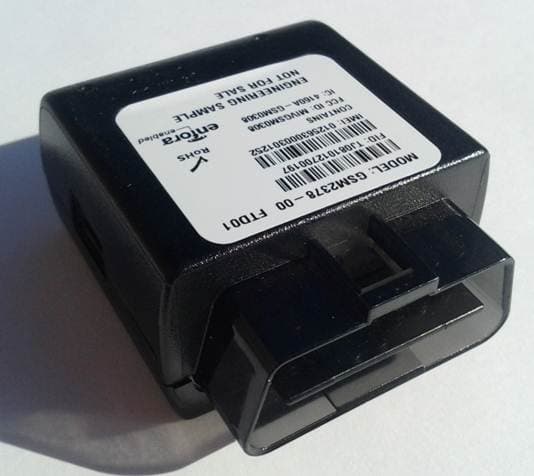
MIVRTT2211
Jan 22, 2013CDMA Licensed Transmitter
Equipment Class
PCB - PCS Licensed Transmitter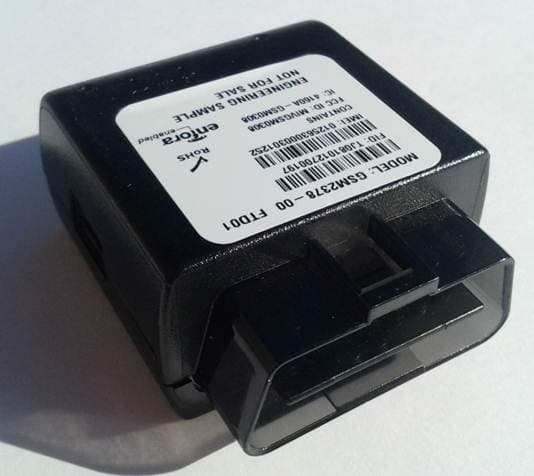
MIVGSM2378
Dec 23, 2012PCS GSM/ GPRS Licensed Transmitter
Equipment Class
PCB - PCS Licensed Transmitter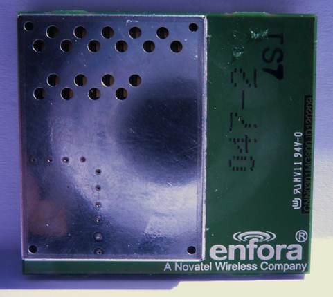
MIVCNN0301
May 10, 20121XRTT Multi-Band M2M OEM Module
Equipment Class
PCB - PCS Licensed Transmitter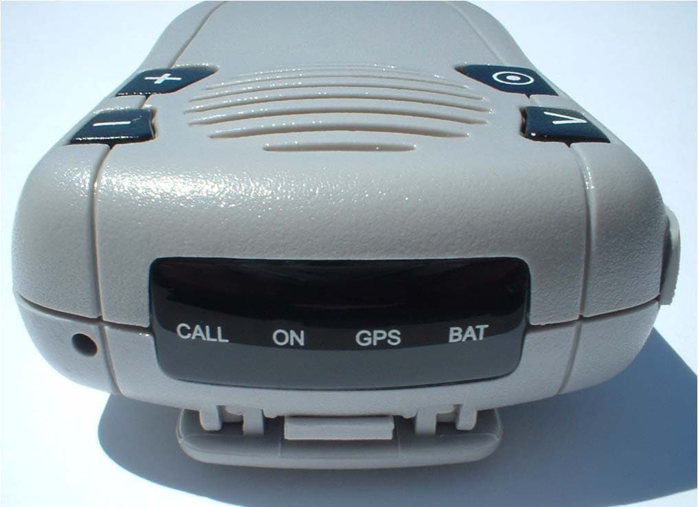
MIVGSM2428
Jun 15, 2011GSM/ GPRS Personal Tracker
Equipment Class
JBP - Part 15 Class B Computing Device Peripheral
MIVGSM5218
Mar 15, 2011GSM/GPRS Asset Tracker
Equipment Class
PCB - PCS Licensed Transmitter