MIVWLN0101Wireless LAN Portfolio
Novatel Wireless Inc.
Click to zoom
Application Details
- Equipment Class
- DTS - Digital Transmission System
- Date of Grant
- Jun 29, 2003
- Application Purpose
- Original Equipment
- Date of Application
- Jun 29, 2003
- Equipment Note
- Wireless LAN Portfolio
- Frequency Range
- 2412.00000000 - 2462.00000000
- Company
- Novatel Wireless Inc.
- Country
- Canada
Documents & Files
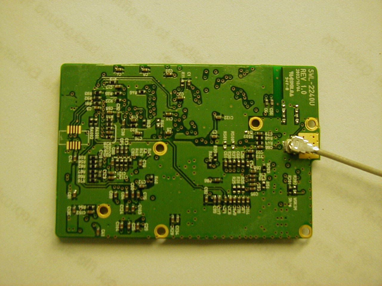
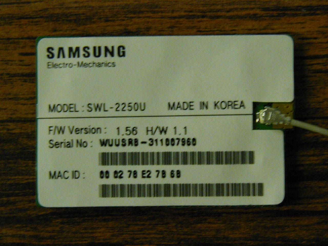
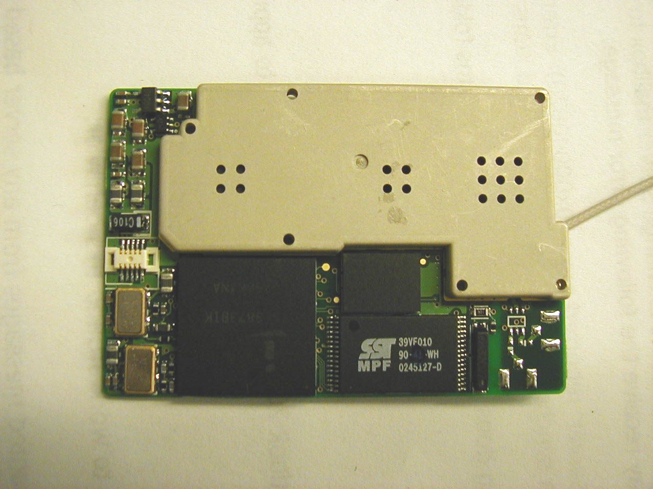
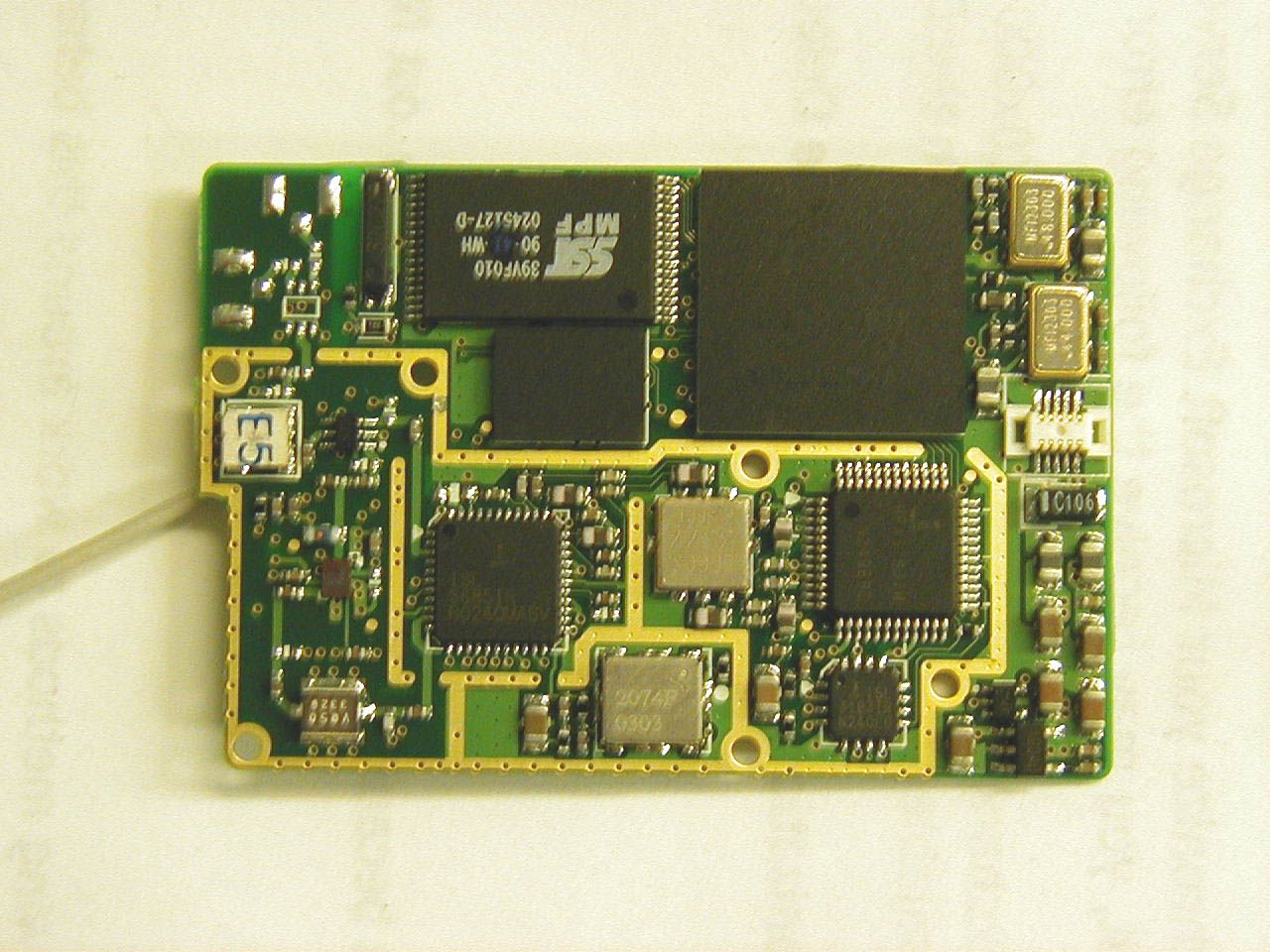
Document Text
Text extracted from the exhibit documents filed with the FCC. Open a document above to read the original.
Users Manual
1 Enfora Wireless Portfolio User Manual 2 This manual is copyrighted. All rights reserved. No portion of this document may be copied, photocopied, reproduced, translated, or reduced to any electronic medium or machine form without prior consent in writing from Enfora, Inc. © 2003 Enfora, Inc. All rights reserved. The information in this document is subject to change without notice and does not represent a commitment on the part of Enfora, Inc. Adobe® Acrobat Reader, © 1987-1999 Adobe Systems Inc. All rights reserved. Adobe and Acrobat are trademarks of Adobe Systems Inc. Enfora, Inc. 661 East 18 th Street Plano, TX 75074 USA www.enfora.com Enfora, Inc. Proprietary Information WP802b001MAN The products and specifications, configurations, and other technical information regarding the services described or referred in this guide are subject to change without notice. All statements, technical information, and recommendations contained in this guide are believed to be accurate and reliable, but are presented “as is”, without warranty of any kind, expressed or implied. Users must take full responsibility for their application of any products specified in this document. Enfora, Inc. makes no implied warranties of merchantability or fitness for a purpose as a result of this guide or the information described within, all other warranties, express or implied, are excluded. 3 Contents Regulatory Information 4 Device Compatibility 5 Getting Started 5 Software Installation 5 Placing the Palm® handheld into the Wireless Portfolio 5 Configuring the Enfora WP802b 5 Entering the Network ID 7 Setting Encryption 8 Selecting the Key Index 9 Selecting the Key Length 10 Saving Settings 11 Connecting 12 Wireless Portfolio LED’s 12 Battery Charging 12 Device Compatibility List 13 4 Regulatory Information The equipment certifications appropriate to your device are marked on the device and product specific information. The use of the equipment is subject to the following conditions: FCC COMPLIANCE STATEMENT This device complies with the limits for a Class B digital device, pursuant to Part 15 of the FCC Rules. Operation is subject to the following two conditions: (1) This device may not cause harmful interference, and (2) this device must accept any interference received, including interference that may cause undesired operation. CAUTION Changes or modifications without the express consent of Enfora, Inc. void the user’s authority to use the equipment. This equipment has been tested and found to comply with the limits for a Class B digital device, pursuant to Part 15 of the FCC Rules. These limits are designed to provide reasonable protection against harmful interference in an appropriate installation. This equipment generates, uses, and can radiate radio frequency energy and, if not used in accordance with instructions, can cause harmful radiation to radio communication. However, there is no guarantee that interference will not occur in a particular installation. If the equipment does cause harmful interference in radio and television reception, which can be determined by turning the equipment on and off, the user is encouraged to try to correct the interference by one or more of the following measures: Reorient or relocate the receiving antenna. Increase the separation distance between the equipment and the receiver. Connect the equipment into an outlet on a circuit different from that to which the receiver is connected. Contact Enfora, Inc. Technical Support for assistance. FCC Radiation Exposure Statement 1. CAUTION: This equipment complies with FCC RF radiation exposure limits set forth for an uncontrolled environment. 2. This Transmitter must not be co-located or operating in conjunction with any other antenna or transmitter. The Federal Communications Commission (FCC) with its action in ET Docket 96-8 has adopted a safety standard for human exposure to radio frequency (RF) electromagnetic energy emitted by FCC certified equipment. Enfora products meet the uncontrolled environmental limits found in OET-65 and ANSI C95.1, 1991.Proper operation of this radio according to the instructions found in this manual and the hardware and software guides on the CD will result in user exposure that is substantially below the FCC recommended limits. 5 Getting Started This section explains how to setup the Enfora WP802b for use with a Palm® handheld device with OS 3.51 – 5.2.1. Software Installation 1. Run the Enfora program 802Mgr.exe and follow the install wizard. The Enfora program is located on the 802.11b beta version CD. 2. After completing the installation you will be prompted to perform a Hotsync. 3. Dock you Palm® device and then perform a HotSync. Placing the Palm® handheld into the Wireless Portfolio ß Adhere the provided female Velcro strip to the back of your Palm® handheld and the male Velcro strip on the inner right side of the Wireless Portfolio. ß Attach the Palm® Universal Adaptor on the Wireless portfolio to your Palm® handheld. ß Place your Palm® handheld on the inner right side of the Wireless Portfolio. Configuring Enfora 802.11b Wireless Portfolio 1. First power on the Wireless Portfolio. The power button is located on the left-hand side of the Wireless Portfolio just above the 2 LED’s. It is placed on the inner edge of the Wireless Portfolio. Next select the Wi-Fi icon from the home screen of your Palm® handheld. 6 2. The Wi-Fi Manager screen will appear. Select the preference icon on you Palm® handheld. 3. Select Network from the Options menu. 7 4. Enter Network ID. The Network ID is also referred to as the SSID. To enter your Network ID Tap on ANY. If your wireless network does not require a Network ID (SSID) you can leave the Network ID as ANY. 5. Entering a new Network ID (SSID). In the Network ID field highlight ANY and then enter your Network ID (SSID) of your access point. 8 6. Encryption level. By default Data Encryption is disabled. To enabled encryption select Data Encryption (WEP enabled…
Text truncated - open the document above for the full version.
Block Diagram
Battery Charger BQ24012 Battery LED Charging LED State ARM Processor PN: AT91R40807 8 KB RAM 0 KB Flash JTAG conn PDA 232 level shift MAX3243CDBR Addr/Data FLASH mem 4Mb 120ns Power Distribution Switch PN:TPS2041A 6MHz XTAL Header/ connector USB UHC124 PLL Memory/MCU Interface Port 1 Port 2 Port 3 Port 4 Palm wall plug 5V Power Condition VBAT 802.11b Samsung USB module SRAM 1Mb OSC/ XTAL 7.3728 MHz Serial Debug USART Power On/Off Control Status LED GPIO Memory Control 3.3V RESET Low Bat LED
Cover Letter(s)
661 East 18 th Street Plano, Texas 75074-5601 972-633-4400 Tel 972-633-4444 Fax www.enfora.com April 16, 2003 Attn: Reviewing Engineer Federal Communications Commission 7435 Oakland Mills Road Columbia, MD 21046 SUBJECT: REQUEST FOR CONFIDENTIALITY FOR WP802b, FCC ID MIVWLN0101 To whom it may concern: This letter serves as an official request for confidentiality under FCC Rule Section 0.459. We have requested that the schematic diagrams (PRT0600MG100) required to be submitted with this application be withheld from public review. This document is company proprietary information that should never get into the possession of our competition. Please contact me if there is any information you may need. Sincerely, Phillip Raymond Sr. Director, Product Development Enfora, Inc. 661 E. 18 th Street Plano, Texas 75074-5601
Cover Letter(s)
661 East 18 th Street Plano, Texas 75074-5601 972-633-4400 Tel 972-633-4444 Fax www.enfora.com April 16, 2003 Attn: Reviewing Engineer Federal Communications Commission 7435 Oakland Mills Road Columbia, MD 21046 SUBJECT: LETTER OF AGENT AUTHORIZATION To whom it may concern: We, the undersigned, hereby authorize MET Laboratories, Inc. to act on our behalf in all matters relating to application for equipment authorization, including the signing of all documents relating to these matters. We also hereby certify that no party to the application authorized hereunder is subject to the denial of benefits, including FCC benefits, pursuant to Section 5301 of the Anti-Drug Abuse Act of 1988,21 U.S.C.853(a). This agreement expires one year from the current date. Sincerely, Phillip Raymond Sr. Director, Product Development Enfora, Inc. 661 E. 18 th Street Plano, Texas 75074-5601
Operational Description
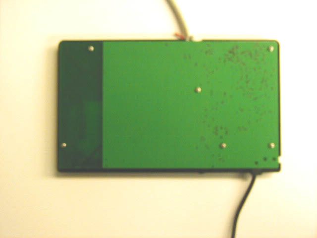
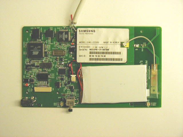
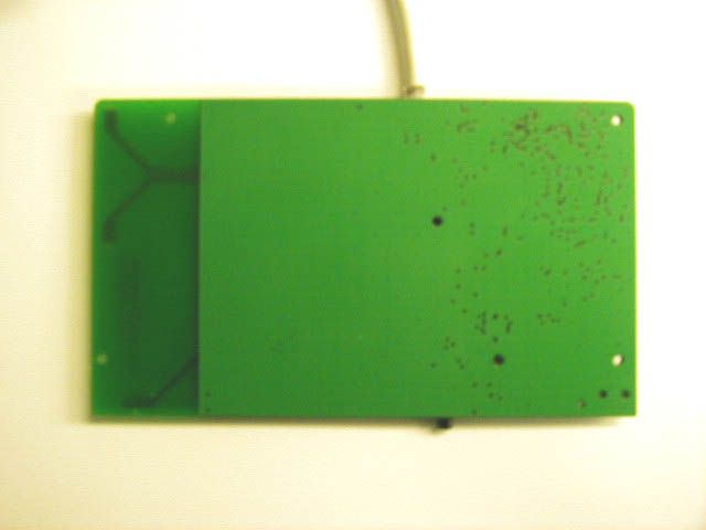
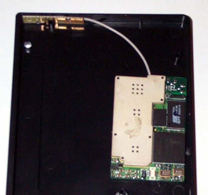
WP802b Antenna Description The Enfora Wireless LAN Portfolio is an 802.11b device that incorporates an internal antenna for wireless communication to external access points. The antenna is a variation of a simple monopole, made of copper etched on PCB, and is connected to the 802.11 module by a 2 inch coaxial cable. To achieve the proper radiation pattern the field around the antenna must be free of any reference ground plane; therefore the antenna is placed in a region of the PCB void of any ground plane (a 1-inch wide area between the ground plane and edge of the PCB.) Normal operation of the antenna is achieved only when the portfolio is completely assembled. The dielectrics of the PCB (FR4 material, 62mil thick, 6-layer stack-up) and the plastic housing that fits over the PCB affect the tuning of the antenna’s center frequency. The combined dielectric of the PCB and the housing tunes the antenna to its nominal center frequency of 2.439GHz, with a bandwidth of 83MHz. Power Management The device uses a single cell 640mA-hr internal non-removable battery with a built-in protection circuit. The charger is a linear charger with internal MOSFET control and external filtering. It is powered by a regulated external 5V wall mount supply. Filtering and circuit protection are accomplished with the use of many shunt capacitors, series coils, and a transorb device on the input power supply rail. The digital circuitry is powered from a 3.3V linear regulator, also with extensive filtering at the regulator as well as the individual IC’s. Battery voltage is monitored with an external ADC. The USB interface is powered by a separate 3.3V linear regulator. Host processor A 32 bit ARM7 core processor controls all interfaces and peripherals. The interface to the 802.11 module is via an external USB host IC, and the interface to the PDA is via a standard 9 wire serial RS232 interface. The processor uses an external 7.3728Mhz clock. The USB interface IC uses an external 6Mhz crystal. Memory The host processor firmware is located in an external flash memory IC, and also has external SRAM. There is a NVRAM for static data such as serial numbers and configuration settings. User Interface Two LEDs are controlled by the host processor to indicate to the user the battery status and network connection status. In addition, the user powers on the device by pressing a momentary switch.
RF Exposure Info
SAR EVALUATION CERTIFICATE OF COMPLIANCE FCC ID: MIVWLN0101 APPLICANT: Enfora Inc. EUT: Wireless Portfolio WP802b Date of Receipt:April 15, 2003 Device Category:Part 15 C RF exposure environment:Uncontrolled RF exposure category:Portable Power supply:Powered by Battery and AC/DC adaptor Antenna:Integrated Antenna Production/prototype:Identical Prototype Measured Standards:Oet 65 Supplement C Modulation:DSSS Crest Factor:DSSS = 1 TX Range:2.4 12– 2.462 GHz RX Range:2.4 12– 2.462 GHz Used TX Channels:Low: ch. 2412 MHzCenter: ch 2437MHzHigh: ch. 2462MHz Maximum RF Power Output:0.09W Conducted Maximum SAR Measurement (averaged over: 1g) 0.782 W/kg Body Len Knight EMC Lab Manager APPLICANT NAME AND ADDRESS: DATE OF TEST:May 7, 2003 Enfora Inc.. TEST LOCATION:MET LABORATORIES INC. 661 East 18th Street 914 West Patapsco Ave. Plano, Texas 75074 Baltimore, Maryland 21230 This wireless portable device has been tested in accordance with the measurement procedures specified in FCC/OET Bulletin 65 Supplement C (2001) and IEEE Std. 1528-200X (July 2001), and has been shown to be capable of compliance for localized specific absorption rate (SAR) for uncontrolled environment/general population exposure limits specified in ANSI/IEEE Std. C95.1 - 1992. I attest to the accuracy of this data. All reported measurements were performed by me, or were made under my supervision, and are correct to the best of my knowledge and belief. I assume full responsibility for the completeness of these measurements and vouch for the qualifications of all persons taking them. I also certify that no party to this application has been denied the FCC benefits pursuant to Section 5.301 of the Anti-Drug Abuse Act of 1988, 21 U.S.C. 862. Enfora Inc. Wireless Portfolio WP802b May 30, 2003 EMC13703-SARCopyright 2003, MET Laboratories, Inc.Page 2 of 43 May 30, 2003 Enfora Inc. 661 East 18th Street Plano, Texas 75074 Reference: Wireless Portfolio WP802b Dear Mr. Phillip Raymond: Enclosed is the EMC SAR Evaluation Report for the Enfora Inc. Wireless Portfolio WP802b was tested in accordance with the measurement procedures specified in FCC OET 65 Supplement C:01-01 and shown to be capable to be in compliance for localized specific absorption rate (SAR) for uncontrolled environment/general population exposure limits specified in FCC OET 65 Supplement C:01-01. Thank you for using the testing services of MET Laboratories. If you have any questions regarding these results or if MET can be of further assistance to you, please feel free to contact me. We appreciate your business and look forward to working with you again soon. Kindest Regards, MET LABORATORIES, INC. Marianne T. Bosley EMC Administrator Enclosures: DOCTEM-23 Jan 02 Certificates and reports shall not be reproduced except in full, without the written permission of MET Laboratories, Inc. The Nation’s First Licensed Nationally Recognized Testing Laboratory Enfora Inc. Wireless Portfolio WP802b May 30, 2003 EMC13703-SARCopyright 2003, MET Laboratories, Inc.Page 3 of 43 Dosimetric Assessment Test Report for the Enfora Inc. Wireless Portfolio WP802b Tested and Evaluated In Accordance With FCC OET 65 Supplement C:01-01 MET REPORT: EMC13703-SAR May 30, 2003 PREPARED FOR: Enfora Inc. 661 East 18th Street Plano, Texas 75074 PREPARED BY: MET Laboratories, Inc. 914 West Patapsco Avenue Baltimore, Maryland 21230-3432 Enfora Inc. Wireless Portfolio WP802b May 30, 2003 EMC13703-SARCopyright 2003, MET Laboratories, Inc.Page 4 of 43 Dosimetric Assessment TEST REPORT for the Enfora Inc. Wireless Portfolio WP802b In Accordance With FCC OET Supplement C: 01-01 Prepared for Enfora Inc. 661 East 18th Street Plano, Texas 75074 Report Prepared By Marianne T. Bosley EMC ADMINISTRATOR Report Reviewed By Liming Xu TEST ENGINEER Final Review By EMC LAB MANAGER Len Knight EMC LAB MANAGER Engineering Statement: The measurements shown in this report were made in accordance with the procedures specified in Supplement C to OET Bulletin 65 of the Federal Communications Commission (FCC) Guidelines [FCC 2001] for uncontrolled exposure. I assume full responsibility for the accuracy and completeness of these measurements, and for the qualifications of all persons taking them. It is further stated that upon the basis of the measurements made, the equipment evaluated is capable of compliance for localized specific absorption rate (SAR) for uncontrolled environment/general population exposure limits specified in ANSI/IEEE Std. C95.1-1992. Enfora Inc.Wireless Portfolio WP802b May 30, 2003 EMC13703-SARCopyright 2003, MET Laboratories, Inc.Page 5 of 43 Quick Links • Summary of test Report • EUT Description • Test Conditions • Host Laptops Used • System Validation • SAR results summary • SAR Area Scans • Setup Pictures • Measurement System Enfora Inc.Wireless Portfolio WP802b May 30, 2003 EMC13703-SARCopyright 2003, MET Laboratories, Inc.Page 6 of 43 OBJECTIVE The objective of the procedure was to perform a dosimetric assessment one of the TDMA cell phone. The measurements have been carried out with the dosimetric assessment system “SARA2", and were made according to the Supplement C to OET Bulletin 65 of the Federal Communications Commission (FCC) Guidelines [FCC 2001] for evaluating compliance of mobile and portable devices with FCC limits for human exposure in the general population to radio frequency emissions. INTRODUCTION In the United States, the most recent FCC RF exposure criteria is documented in the publication OET 65 Supplement C Edition 01-01 [FCC 2001], which sets limits for human exposure to radio frequency electromagnetic fields in the frequency range 3kHz to 300GHz. The safety limits used for the environmental evaluation measurements are based on the criteria published by the American National Standards Institute (ANSI) for localized specific absorption rate (SAR) in IEEE/ANSI C95.1-1992 Standard for Safety Levels with Respect to Human Exposure to Radio Frequency Electromagnetic Fields, 3 kHz to 300 …
Text truncated - open the document above for the full version.
RF Exposure Info
IMMERSIBLE SAR PROBE CALIBRATION REPORT Part Number: IXP – 050 S/N 0122 25 th October 2002 Indexsar Limited Oakfield House Cudworth Lane Newdigate Surrey RH5 5DR Tel: +44 (0) 1306 631 233 Fax: +44 (0) 1306 631 834 e-mail: [email protected] INTRODUCTION This Report presents measured calibration data for a particular Indexsar SAR probe (S/N 0122) and describes the procedures used for characterisation and calibration. Indexsar probes are characterised using procedures that, where applicable, follow the recommendations of CENELEC [1] and IEEE [2] standards. The procedures incorporate techniques for probe linearisation, isotropy assessment and determination of liquid factors (conversion factors). Calibrations are determined by comparing probe readings with analytical computations in canonical test geometries (waveguides) using normalised power inputs. Each step of the calibration procedure and the equipment used is described in the sections below. CALIBRATION PROCEDURE 1. Equipment Used For the first part of the characterisation procedure, the probe is placed in an isotropy measurement jig as pictured in Figure 1. In this position the probe can be rotated about its axis by a non-metallic belt driven by a stepper motor. The probe is attached via its amplifier and an optical cable to a PC. A schematic representation of the test geometry is illustrated in Figure 2. A balanced dipole (900 MHz) is inserted horizontally into the bracket attached to a second belt (Figure 1). The dipole can also be rotated about its axis. A cable connects the dipole to a signal generator, via a directional coupler and power meter. The signal generator feeds an RF amplifier at constant power, the output of which is monitored using the power meter. The probe is positioned so that its sensors line up with the rotation center of the source dipole. By recording output voltage measurements of each channel as both the probe and the dipole are rotated, data are obtained from which the spherical isotropy of the probe can be optimised and its magnitude determined. The calibration process requires E-field measurements to be taken in air, in 900 MHz simulated brain liquid and at other frequencies/liquids as appropriate. 2. Linearising probe output The probe channel output signals are linearised in the manner set out in Refs [1] and [2]. The following equation is utilized for each channel: U lin = U o/p + U o/p 2 / DCP (1) where U lin is the linearised signal, U o/p is the raw output signal in voltage units and DCP is the diode compression potential in similar voltage units. DCP is determined from fitting equation (1) to measurements of U lin versus source feed power over the full dynamic range of the probe. The DCP is a characteristic of 3 the schottky diodes used as the sensors. For the IXP-050 probes with CW signals the DCP values are typically 0.10V (or 20 in the voltage units used by Indexsar software, which are V*200). 3. Selecting channel sensitivity factors to optimise isotropic response The basic measurements obtained using the calibration jig (Fig 1) represent the output from each diode sensor as a function of the presentation angle of the source (probe and dipole rotation angles). The directionality of the orthogonally-arranged sensors can be checked by analysing the data using dedicated Indexsar software, which displays the data in 3D format as in Figure 3. The left-hand side of this diagram shows the individual channel outputs after linearisation (see above). The program uses these data to balance the channel outputs and then applies an optimisation process, which makes fine adjustments to the channel factors for optimum isotropic response. The next stage of the process is to calibrate the Indexsar probe to a W&G EMR300 E- field meter in air. The principal reasons for this are to obtain conversion factors applicable should the probe be used in air and to provide an overall measure of the probe sensitivity. A multiplier is applied to factors to bring the magnitudes of the average E-field measurements as close as possible to those of the W&G probe. The following equation is used (where linearised output voltages are in units of V*200): E air 2 (V/m) = U linx * Air Factor x + U liny * Air Factor y + U linz * Air Factor z (2) It should be noted that the air factors are not separately used for normal SAR testing. The IXP-050 probes are optimised for use in tissue-simulating liquids and do not behave isotropically in air. 4. 900 MHz Liquid Calibration Conversion factors for use when the probes are immersed in tissue-simulant liquids at 900 MHz are determined either using a waveguide or by comparison to a reference probe that has been calibrated by NPL. Waveguide procedures are described later. The summary sheet indicates the method used for the probe S/N 0122. The conversion factor, referred to as the ‘liquid factor’ is also applied to the measurements of each channel. The following equation is used (where output voltages are in units of V*200): E liq 2 (V/m) = U linx * Air Factor x * Liq Factor x + U liny * Air Factor y * Liq Factor y + U linz * Air Factor z * Liq Factor z (3) A 3D representation of the spherical isotropy for probe S/N 0122 using these factors is shown in Figure 3. 4 The rotational isotropy can also determined from the calibration jig measurements and is reported as the 900MHz isotropy in the summary table. Note that waveguide measurements can also be used to determine rotational isotropy (Fig. 5). The design of the cells used for determining probe conversion factors are waveguide cells is shown in Figure 4. The cells consist of a coax to waveguide transition and an open-ended section of waveguide containing a dielectric separator. Each waveguide cell stands in the upright positition and is filled with liquid within 10 mm of the open end. The seperator provides a liquid seal and is designed for a good electrical transition from air filled guide to liquid filled guide. The choice of cell depends on th…
Text truncated - open the document above for the full version.
Test Report
The Nation's First Licensed Nationally Recognized Testing Laboratory Conceil canadien des nomes Organisme de certification accedite Standards Council of Canada Accredited Certification Organization TM MET Laboratories, Inc. Safety Certification - EMI - Telecom Environmental Simulation 914 WEST PATAPSCO AVENUE !! BALTIMORE, MARYLAND 21230-3432 !! PHONE (410) 354-3300 !! FAX (410) 354-3313 June 21, 2003 Enfora Inc. 661 East 18th Street Plano, Texas 75074 Reference: Wireless Portfolio WP802b FCC ID: MIVWLN0101 Dear Mr. Phillip Raymond: Enclosed is the EMC Test Report for the Enfora Inc.. The Enfora Inc Wireless Portfolio WP802b was tested to the requirements of the FCC Rules and Regulations, Section 15.247, of Title 47 of the CFR, for a Part 15 Transmitter. Thank you for using the testing services of MET Laboratories. If you have any questions regarding these results or if MET can be of further assistance to you, please feel free to contact me. We appreciate your business and look forward to working with you again soon. Kindest Regards, MET LABORATORIES, INC. Marianne T. Bosley Documentation Department Enclosures: (\Enfora Inc.\EMC13703-FCC247.rpt) DOCTEM-23 Jan 02 Certificates and reports shall not be reproduced except in full, without the written permission of MET Laboratories, Inc. While use of the National Voluntary Laboratory Accreditation Program (NVLAP) letters or the NVLAP Logo in this report reflects the MET Accreditation under the NVLAP Program, these letters, logo, or Statements do not claim product endorsement by NVLAP or any Agency of the U.S. Government. Enfora Inc. Wireless Portfolio WP802b FCC ID: MIVWLN0101June 21, 2003 Electro-Magnetic Compatibility Test Report for the Enfora Inc. Wireless Portfolio WP802b Tested Under FCC Part 15 Subpart C Section 15.247 Title 47 of the CFR for Intentional Radiators MET REPORT: EMC13703-FCC247 June 20, 2003 PREPARED FOR: Enfora Inc. 661 East 18th Street Plano, Texas 75074 PREPARED BY: MET Laboratories, Inc. 914 West Patapsco Avenue Baltimore, Maryland 21230-3432 Copyright 2003, MET Laboratories, Inc. This report shall not be reproduced except in full, without the express written consent of MET Laboratories, Inc., nor shall this report, or any copy thereof be provided to a competitor of MET Laboratories, Inc. Enfora Inc. Wireless Portfolio WP802b FCC ID: MIVWLN0101June 21, 2003 MET Report: EMC13703-FCC247Copyright 2003, MET Laboratories, Inc.Page ii of v Electro-Magnetic Compatibility Test Report for the Enfora Inc. Wireless Portfolio WP802b Tested Under FCC Part 15 Subpart C Section 15.247 Title 47 of the CFR for Intentional Radiators MET REPORT: EMC13703-FCC247 June 20, 2003 PREPARED FOR: Enfora Inc. 661 East 18th Street Plano, Texas 75074 ______________________________________________________________ Christopher R. Harvey, DirectorMarianne T. Bosley Electromagnetic Compatibility TestingReport Writer Engineering Statement: The measurements shown in this report were made in accordance with the procedures indicated, and the emissions from this equipment were found to be within the limits applicable. I assume full responsibility for the accuracy and completeness of these measurements, and for the qualifications of all persons taking them. It is further stated that upon the basis of the measurements made, the equipment tested is capable of operation in accordance with the requirements of Part 15, Section 15.247, of the FCC Rules under normal use and maintenance. ________________________________ Liming Xu Project Engineer Enfora Inc. Wireless Portfolio WP802b FCC ID: MIVWLN0101June 21, 2003 MET Report: EMC13703-FCC247Copyright 2003, MET Laboratories, Inc.Page iii of v Table of Contents I. Executive Summary...........................................................................1 A.Purpose of Test.......................................................................2 B.Executive Summary....................................................................2 II. General.....................................................................................3 A.Test Site.............................................................................4 B.Description of Test Sample..............................................................4 C.General Test Setup....................................................................4 D.Mode of Operation....................................................................4 E.Modifications.........................................................................7 F.Disposition of Test Sample..............................................................7 III. Antenna Requirements.........................................................................8 IV. Emissions Requirements......................................................................10 A.Conducted Emissions.................................................................11 B.Radiated Emissions - General...........................................................17 V.Bandwidth & Bandedge Requirements...........................................................20 VI. Peak Output Power Requirements...............................................................26 A.Peak Output Power (Conducted).........................................................27 B.RF Exposure Requirements.............................................................29 VII. Spurious Emissions - Radiated & RF Conducted - Requirements.......................................30 VIII. Power Spectral Density Requirements............................................................37 IX.Test Equipment.............................................................................41 X.Certification Label & User's Manual Information...................................................43 A.Certification Information...............................................................44 B.Label and User's Manual Information.....................................................47 Enfora Inc. Wireless Portfolio…
Text truncated - open the document above for the full version.
Contact Information
Applicant
Todd Gallagher(Manager, Regulatory Engineering)
Test Firm
MET Laboratories, Inc.John Mason
Technical Specifications
| # | Rule Parts | Frequency Range | Power Output |
|---|---|---|---|
| 1 | 15C | 2.41 GHz - 2.46 GHz | 90.00 mW |
Other Applications from Novatel Wireless Inc.
MIVRTT2211
Jan 22, 2013CDMA Licensed Transmitter
Equipment Class
PCB - PCS Licensed Transmitter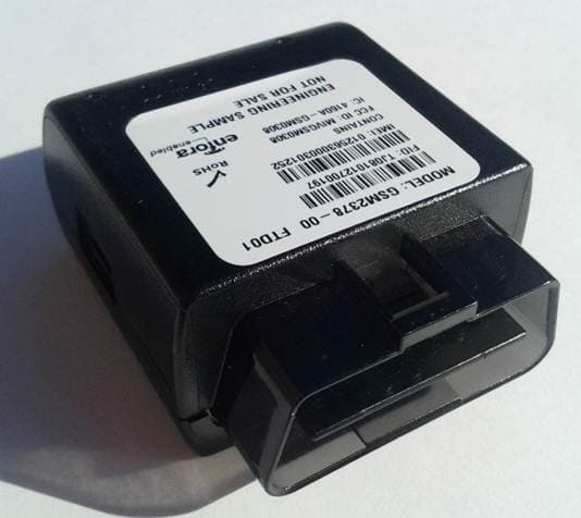
MIVGSM2378
Dec 23, 2012PCS GSM/ GPRS Licensed Transmitter
Equipment Class
PCB - PCS Licensed Transmitter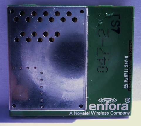
MIVCNN0301
May 10, 20121XRTT Multi-Band M2M OEM Module
Equipment Class
PCB - PCS Licensed Transmitter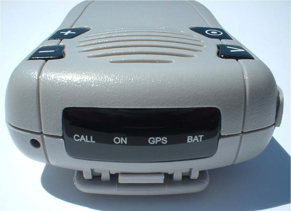
MIVGSM2428
Jun 15, 2011GSM/ GPRS Personal Tracker
Equipment Class
JBP - Part 15 Class B Computing Device Peripheral
MIVGSM5218
Mar 15, 2011GSM/GPRS Asset Tracker
Equipment Class
PCB - PCS Licensed Transmitter