MIVWLN1501Wi-Fi Adapter Module
Novatel Wireless Inc.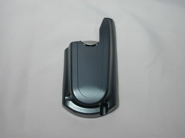
Click to zoom
Application Details
- Equipment Class
- DTS - Digital Transmission System
- Date of Grant
- Sep 06, 2005
- Application Purpose
- Original Equipment
- Date of Application
- Sep 06, 2005
- Equipment Note
- Wi-Fi Adapter Module
- Frequency Range
- 2412.00000000 - 2462.00000000
- Company
- Novatel Wireless Inc.
- Country
- Canada
Documents & Files
Document Text
Text extracted from the exhibit documents filed with the FCC. Open a document above to read the original.
Users Manual
Enfora Wi-Fi Adapter for Treo 600/650 Smartphone Users Manual Version 1.0 Enfora L.P. 661 E. 18 th Street Plano Texas 75074 www.enfora.com WLN150x Wi-Fi Adapter ii Copyright Statement Copyright 2004 by Enfora L.P. All rights reserved. No portion of this document may be copied, photocopied, reproduced, transmitted, transcribed, stored in a retrieval system or translated into any language or computer language, in any form or by any means, electronic, mechanical, magnetic, optical, chemical, manual or otherwise, without the prior written permission of Enfora L.P. © 2004 Enfora, L.P. All rights reserved. Disclaimer Enfora L.P. makes no representations or warranties, either expressed or implied, with respect to the contents hereof and specifically disclaims any warranties, merchantability or fitness for any particular purpose. Further, Enfora L.P. reserves the right to revise this publication, and to make changes from time to time in the contents hereof without obligation of Enfora L.P. to notify any person of such revision or changes. ALL INFORMATION IS PROVIDED BY ENFORA L.P. ON AN “AS IS” BASIS ONLY. THIS COMPANY PROVIDES NO REPRESENTATIONS AND WARRANTIES, EXPRESS OR IMPLIED, INCLUDING THE IMPLIED WARRANTIES OF FITNESS FOR A PARTICULAR PORPOSE, MERCHANTABILITY AND NONINFRINGEMENT. All product names mentioned within this document are the trademark of their respective owners. Enfora, LP. Proprietary Information WLN1501MAN001 Adobe® Acrobat Reader, © 1987-1999 Adobe Systems Inc. All rights reserved. Adobe and Acrobat are trademarks of Adobe Systems Inc. WLN150x Wi-Fi Adapter iii Safety Information for Wireless Handheld Devices The equipment certifications appropriate to your device are marked on the device and product specific information. The use of the equipment is subject to the following conditions: FCC COMPLIANCE STATEMENT This device complies with the limits for a Class B digital device, pursuant to Part 15 of the FCC Rules. Operation is subject to the following two conditions: (1) This device may not cause harmful interference, and (2) this device must accept any interference received, including interference that may cause undesired operation. CAUTION Changes or modifications without the express consent of Enfora, Inc. void the user’s authority to use the equipment. This equipment has been tested and found to comply with the limits for a Class B digital device, pursuant to Part 15 of the FCC Rules. These limits are designed to provide reasonable protection against harmful interference in an appropriate installation. This equipment generates, uses, and can radiate radio frequency energy and, if not used in accordance with instructions, can cause harmful radiation to radio communication. However, there is no guarantee that interference will not occur in a particular installation. If the equipment does cause harmful interference in radio and television reception, which can be determined by turning the equipment on and off, the user is encouraged to try to correct the interference by one or more of the following measures: Reorient or relocate the receiving antenna. Increase the separation distance between the equipment and the receiver. Connect the equipment into an outlet on a circuit different from that to which the receiver is connected. Contact Enfora, Inc. Technical Support for assistance. FCC Radiation Exposure Statement 1. CAUTION: This equipment complies with FCC RF radiation exposure limits set forth for an uncontrolled environment. 2. This Transmitter must not be co-located or operating in conjunction with any other antenna or transmitter. The Federal Communications Commission (FCC) with its action in ET Docket 96-8 has adopted a safety standard for human exposure to radio frequency (RF) electromagnetic energy emitted by FCC certified equipment. Enfora products meet the uncontrolled environmental limits found in OET-65 and ANSI C95.1, 1991.Proper operation of this radio according to the instructions found in this manual and the hardware and software guides on the CD will result in user exposure that is substantially below the FCC recommended limits. Customers in European countries Battery is not replaceable, for service center only. CAUTION RISK OF EXPLOSION IF BATTERY IS REPLACED BY INCORRECT TYPE. DISPOSE OF BATTERIES ACCORDING TO THE INSTRUCTIONS. WLN150x Wi-Fi Adapter iv Use the following or equivalent certified Power Supply. Make: PHIHONG, Model PSA11R-050 Rated Input: 100-240Vac, 0.5A, 50-60hz, DC Output: 5V DC, 2.0A Limited Power Source. WLN150x Wi-Fi Adapter v General Safety Instructions • Check if all peripherals are properly connected before turning on any equipment. • Make sure to disconnect the power plug from the power source before installing or removing peripherals. • Always hold the product with dry hands. Droplets of water may cause it to short circuit and damage to the product. • Use the product only under a dry environment. Humid places are not appropriate for the product. • DO NOT use the product in a damp environment. • DO NOT place the product on an unstable surface. Keep the product out of the reach of children. • DO NOT share the same extension power line for the product with high power- consuming appliances to avoid power overload. • NEVER attempt to disassemble the product! Doing so may cause permanent damage to the product and will void the warranty. WLN150x Wi-Fi Adapter vi Package Contents Check the contents of the package. The following items should be included. If there is any item that is damaged or missing, please contact your dealer immediately. Description Quantity Enfora Wi-Fi Adapter for Treo Smartphone 1 Install CD-ROM 1 Battery Cover Door for the Treo 650 1 WLN150x Wi-Fi Adapter vii Lock Release Button Appearance Enfora Wi-Fi Adapter for Treo Smartphone Treo Smartphone Headphone Jack Wi-Fi Adapter DC Power Input Treo Smartphone Headphone Jack Lock Release Button Network/ Battery Status LED Power On/Off Button WLN150x Wi-Fi Adapter viii Netwo…
Text truncated - open the document above for the full version.
Attestation Statements
Enfora L.P. 661 E. 18 th Street Plano, TX 75074-5601 (972) 633-4400 Fax (972) 633-4444 Federal Communications Commission 7435 Oakland Mills Road Columbia, MD 21046 Authority to Act as Agent to the Federal Communications Commission On our behalf, I appoint Nemko Dallas, Inc. to act as agent in the preparation of this application for (Enfora model WLN1501) equipment authorization to the Federal Communications Commission. I certify that submitted Exhibits properly describe the device or system for which equipment authorization is sought. I also certify that each unit manufactured, imported or marketed, as defined in the Commission's regulations will have affixed to it a label identical to that submitted for approval with this application. APPLICANT ANTI-DRUG ABUSE CERTIFICATION: In signing this letter, Applicant certifies that, in the case of an individual applicant, he or she is not subject to a denial of federal benefits, that includes FCC benefits, pursuant to Section 5301 of the Anti-Drug Abuse Act of 1988, 21 U.S.C. 853(a), or, in the case of a non-individual applicant (e.g. corporation, partnership or other unincorporated association), no party to the application is subject to a denial of federal benefits, that includes FCC benefits, pursuant to that section. For the definition of a "party" for these purposes, see 47 CFR 1.2002(b). Date: August 11, 2005 Agency agreement expiration date: August 11, 2006 By: Bill Wrightson Title: Sr. Director, Product Development Telephone: 972-633-4430 Applicant: Enfora L.P., 661 E. 18 th St., Plano, TX 75074
Cover Letter(s)
Enfora L.P. 661 E. 18 th Street Plano, TX 75074-5601 (972) 633-4400 Fax (972) 633-4444 August 11, 2005 Equipment Autorisation Division Federal Communications Commission 7435 Oakland Mills Road Columbia, MD 21046 FCC ID: MIVWLN1501 Product Name: Wi-Fi ® Adapter REQUEST FOR CONFIDENTIALITY Enfora L.P. requests confidentiality pursuant to Sections 0.457 and 0.459 of the commissions rules with regard to the following documents: (1) Schematic diagrams contained in electronic file WLN1502MG801SCH_Rev3.PDF. (2) Schematic diagrams contained in electronic file WLN1502MG810SCH_Rev2.PDF. (3) Block Diagram contained in electronic file treo_sled_block_diagram.PDF. These materials contain trade secrets and proprietary information and are not customarily released to the public. The public disclosure of this information might be harmful to the company and provide unjustified benefits to our competitors. It is the opinion of Enfora Inc. that disclosure of this information would result in significant loss of revenue. These documents are also covered under multiple non-disclosure agreements with other companies. This information should be kept confidential for 5 years. Bill Wrightson Sr. Director, Product Development Enfora L.P. 661 E. 18 th St Plano, TX 75074 972-633-4400
Cover Letter(s)
August 31, 2005 To Whom It May Concern: Enfora Inc. would like to apply for Limited Modular FCC approval. This letter is our request for such according to FCC public notice DA 00-1407. MN1501 Limited Modular Transmitter Requirements Modular Transmitter Requirements Manufacturer Clarification A – In order to be considered a transmitter module, the device must be a complete RF transmitter, i.e., it must have its own reference oscillator (e.g., VCO), antenna, etc. The only connectors to the module, if any, may be the power supply and modulation/data inputs. The transmitter is complete with its own reference oscillator, antenna, and voltage regulation.. The only connectors provided are the DC Supply and Data. B – Compliance with FCC RF Exposure requirements may, in some instances, limit the output power of a module and/or the final applications in which the approved module may be employed. The radio complies with MPE per 2.1091 for use as a portable device. C – While the applicant for a device into which an authorized module is installed is not required to obtain a new authorization for the module, this does not preclude the possibility that some other form of authorization or testing may be required for the device (e.g., a WLAN into which an authorized module is installed must still be authorized as a PC peripheral, subject to the appropriate equipment authorization). The equipment complies with FCC Part 15, Subpart B, Class B – Unintentional radiators. The device with which the module is intended to operate holds a certification as a licensed device. D – In the case of a modular transceiver, the modular approval policy only applies to the transmitter portion of such devices. Pursuant to Section 15.101(b), the receiver portion will either be subject to Verification, or it will not be subject to any authorization requirements (unless it is a Scanning Receiver, in which case it is also subject to Certification, pursuant to Section 15.101(a)). The receiver operates in 2412 – 2462 MHz band. Modular Transmitter Requirements Manufacturer Clarification E – The holder of the grant of equipment authorization (Grantee) of the module is responsible for the compliance of the module in its final configuration, provided that the OEM, integrator, and/or end user has complied with all of the instructions provided by the Grantee which indicate installation and/or operating conditions necessary for compliance. End users must conform with the following instructions stated in the users’ manual: - Labeling requirement for equipment using this modular transmitter. - RF Exposure information for compliance with FCC Rules 2.1091 or 2.1093 are specified in the user manual for OEM, integrator, and/or end user. 1. The modular transmitter must have its own RF shielding. This is intended to ensure that the module does not have to rely upon the shielding provided by the device into which it is installed in order for all modular transmitter emissions to comply with Part 15 limits... Such coupling may result in non-compliant operation. The modular transmitter has its own RF shielding. 2. The modular transmitter must have buffered modulation/data inputs (if such inputs are provided) to ensure that the module will comply with Part 15 requirements under conditions of excessive data rates or over-modulation. The modular transmitter has buffered modulation/data inputs. 3. The modular transmitter must have its own power supply regulation. This is intended to ensure that the module will comply with Part 15 requirements regardless of the design of the power supplying circuitry in the device into which the module is installed. The modular transmitter has its own power supply regulation. 4. The modular transmitter must comply with the antenna requirements of Section 15.203 and 15.204c. The antenna must either be permanently attached or employ a “unique” antenna coupler (at all connections between the module and the antenna, including the cable). Any antenna used with the module must be approved with the module; either at the time of initial authorization or through a Class II permissive change. The “professional installation” provision of Section 15.203 may not be applied to modules. The radio complies with Rules 15.203 and 15.204c. The antenna is integral to the module. Modular Transmitter Requirements Manufacturer Clarification 5. The modular transmitter must be tested in a stand-alone configuration, i.e., the module must not be inside another device during testing. This is intended to demonstrate that the module is capable of complying with Part 15 emission limits regardless of the device into which it is eventually installed... The modular transmitter was tested in a stand-alone configuration. 6. The modular transmitter must be labeled with its own FCC ID number, and, if the FCC ID is not visible when the module is installed inside another device, then the outside of the device into which the module is installed must also display a label referring to the enclosed module... The modular transmitter is labeled with its own FCC ID number. The label is fixed on the plastic housing of the modular device. 7. The modular transmitter must comply with any specific rule or operating requirements applicable to the transmitter and the manufacturer must provide adequate instructions along with the module to explain any such requirements. The user manual contains adequate instructions relating to the usage, approved antennas, and power supply requirements of the modular transmitter. 8. The modular transmitter must comply with any applicable RF exposure requirements. The modular transmitter is exempt from a routine SAR evaluation due to the fact that the rf output power is 9 mW conducted (14.5 mW eirp). Bill Wrightson Title: Sr. Director, Product Development Telephone: 972-633-4430 Applicant: Enfora L.P., 661 E. 18 th St., Plano, TX 75074
ID Label/Location Info
These drawings and specifications are the property of Enfora. All information contained herein which is not known generally in the field shall be confidential except to the extent to which it is established to have been previously from sou rces other than Enfora. These drawings and specifications may not be reproduced, copied, o r used as the basis for the manufacture or sale of apparatus without written permission. Label Requirements: 1) Text as shown 2) Black Text on White Background 3) Character Height – 0.075 inches Material Requirements: 4) Glossy White Permanent Polyester 5) Non Transparent 6) Ink Must be permanent 0.75 inches Enfora, L.P. 661 E. 18 th Street Plano, Texas 75074 www.enfora.com TITLE Label, FCC, WLN1501 Sled WLN1501PB004 DWG No. WLN1501PB004 REV A SHEET 1 of 1 SIZE B SCALE none 1.5 inches
Operational Description
BGW200 Low-power WLAN SiP Complete, single-package 802.11b solution for mobile handheld devices Optimized for low-power mobile applications, this complete, single-package 802.11b solution combines a baseband/MAC, RF transceiver, and power amplifier into an ultra-small (150 mm 2 ) package. It delivers the industry’s lowest power consumption in standby mode and supports coexistence with Bluetooth ® solutions. Semiconductors The BGW200 is a complete, low-power 802.11b Wireless LAN (WLAN) System-in-a-Package (SiP) solution optimized for battery-powered hand- held devices. It enables consumers to connect to the growing number of WLAN networks in offices, homes, and public places. It also allows service providers to increase their network reach and customer base, enabling complementary data and voice services across cellular/PCS and WLAN networks. Coexistence support for Bluetooth 1.1 and 1.2 enables seamless integration with Philips Bluetooth solutions. The SiP format, with its complete system functionality, delivers quicker design cycles, lower risk, simplified manufacturing, and a reduced bill of materials. The single-package format also simplifies assembly and testing, and reduces yield losses. The SiP delivers a complete, fully tested imple- mentation of 802.11b functionality, so development teams can focus their energy on innovative product design instead of solving complex issues related to RF layout. Ultra-small footprint, ultra-low power consumption The BGW200 uses a single, 68-pin HVQFN-like package that measures only 10 x 15 x 1.3 mm. The entire 802.11b solution requires only three external components and uses less than 180 mm 2 of circuit board area. The BGW200 incorporates several features that decreases power con- sumption. There is an integrated ARM7 processor, 1.25 Mbytes of SRAM, 256 Kbytes of ROM, optimized host interfaces (SDIO/SPI), and integrated power management hardware/software algorithms. The result is the lowest standby power consumption in the industry (less than 2 mW). Superior “No Host Load” Architecture The BGW200 is designed to place no load on the host processor, so mobile devices can integrate WLAN functionality without compromis- ing application performance or battery life. The BGW200 only interfaces Key features • Advanced, single-package WLAN SiP optimized for mobile handheld devices – No RF-critical design required – Low total cost of ownership • Lowest power consumption in standby mode: < 2 mW (typ) • Ultra-small form factor – Low-profile 68-pin HVQFN-like SiP package (10 x 15 x 1.3 mm) – Only three external components for entire solution • “No Host Load” design delivers easy integration and longer battery life – Host processor sleeps while BGW200 processes beacons – BGW200 wakes the host processor only upon data packet arrival • Co-exists with Bluetooth 1.1 and 1.2 • Complete software drivers, utility, and diagnostic tools Applications • Smartphones, cellular phones, VoIP wireless phones • PDAs, handheld computing devices, WLAN adapter cards (Secure Digital) • Portable audio/video devices, MP3 players • Other handhelds and electronic devices for wireless digital, audio, multi- media, and telephony BGW200 Low-power 802.11b SiP with baseband/MAC and RF transceiver for mobile handhelds Semiconductors with the host processor when a valid data packet is received. So the host processor is allowed to sleep while the BGW200 independently processes 802.11 beacons. The MAC protocol runs on an embedded ARM7 processor, for zero overhead on the host processor. An instruction prefetch unit enhances the performance of the ARM7. To support new MAC protocol features, the BGW200 is also designed to support firmware upgrades. Bluetooth coexistence The BGW200 is designed to support collaborative coexistence between 802.11 and Bluetooth 1.1 and 1.2. A dedicated software and hardware interface implements Packet Traffic Arbitration (PTA) with voice priority between the BGW200 and the Bluetooth system. An auto shutdown feature ensures that Bluetooth voice takes priority over other signals and there is special support for burst and fragmented frames. Bluetooth 1.2 enhances coexistence further, by adding independent Adaptive Frequency Hopping (AFH) capability. The Philips BGB20x family of Bluetooth SiPs is designed to interface and coexist seamlessly with the BGW200. Supports latest QoS and security standards Advanced hardware and software algorithms, along with Wi-Fi Multi- media Extensions (WME), provide advanced Quality of Service (QoS) functions. This lets the BGW200 support real-time applications like VoIP and non-real-time applications like email and web surfing. The BGW200 is also designed to support the upcoming 802.11e standard. The BGW200 has advanced security features, including 40- and 128-bit WEP, WPA, CCX (Cisco Security), TKIP, and AES. The SiP is also de- signed to support the upcoming 802.11i extension. Advanced RF subsystem The integrated RF transceiver supports transmit output power control from +8 to +18 dBm at the antenna port – enabling optimal range, throughput, and power consumption. The integrated RF transceiver uses a direct conversion radio architecture that minimizes external compo- nents and eliminates the IF filter. For additional component reduction, the integrated PA is internally matched to the ZIF radio. In addition to the radio transceiver and power amplifier, the BGW200 also integrates an Rx/Tx diversity switch, bandpass filter, balun, power supply decou- pling, and other passive components. Reference designs and eval kits Reference design software drivers support PocketPC™ and Linux™ operating systems. Drivers for Palm™ and Symbian™ are in develop- ment. The BGW200 is backed by a complete set of software utility and diagnostic tools, and is available in evaluation kits. Frequency Bands2.4 to 2.5 GHz ModulationsDBPSK, DQPSK, CCK (DSSS) Data Rates1, 2, 5.5, 11 Mbps SiP Power Consumption (typical)Tx: 731 mW @ 15 dBm Rx: 415 mW Standby: < 2 mW Slee…
Text truncated - open the document above for the full version.
Operational Description
WLN1501 Circuit Description Enfora LP. 661 E. 18 th Street Plano, TX 75074-5601 (972) 633-4400 Fax (972) 633-4444 Operational Description The WLN1501 Wi-Fi ® Adapter Sled utilizes a highly integrated transceiver that provides virtually all radio functions. Circuitry & Devices Provided for Determining & Stabilizing Frequency System Reference Clock: The WiFi module generates all internal clocks from a 44.000 MHz external reference clock. The 44 MHZ reference clock is a crystal Colpitts oscillator. Circuitry & Devices Provided for Suppression of Spurious Radiation All RF circuitry is contained within the WiFi module. A quarter-wave linear antenna is the only external RF component in the design. Circuitry & Devices Provided for Limiting Modulation All modulation waveforms are generated internal to the WiFi module. Circuitry & Devices Provided for Limiting Power All power control is implemented internal to the WiFi module. Circuitry & Devices Provided for USB communications The USB interface is accomplished by using a single chip USB controller with integrated transceiver. The controller utilizes a 6 MHz reference oscillator to generate an internal clock of 48MHz to meet the USB 2.0 specification data rate of up to 12Mbps. Data rates are < 1 Mbps for this application.
Parts List/Tune Up Info
Enfora L.P. 661 E. 18 th Street Plano, TX 75074-5601 (972) 633-4400 Fax (972) 633-4444 August 11, 2005 Tuning Procedure Power Factory Set, No Tune up provisions needed for the WLN1501 product identified by FCC ID. No. MIVWLN1501. Bill Wrightson Sr. Director, Product Development Enfora L.P. 661 E. 18 th St Plano, TX 75074 972-633-4400
RF Exposure Info
Prediction of MPE limit at a given distance Equation from page 18 of OET Bulletin 65, Edition 97-01 where:S = power density P = power input to the antenna G = power gain of the antenna in the direction of interest rel. to an isotropic radiator R = distance to the center of radiation of the antenna Maximum peak output power at antenna input terminal:9.50(dBm) Maximum peak output power at antenna input terminal:9(mW) Antenna gain(typical):2.15(dBi) Maximum antenna gain:1.64059(numeric) Prediction distance:2(cm) Prediction frequency:2400(MHz) MPE limit for uncontrolled exposure at prediction frequency:1(mW/cm^2) Power density at prediction frequency:0.293746(mW/cm^2) 2 4R PG S π =
Test Report
Nemko Test Report: 5L0047RUS1 Applicant: Enfora 661 E. 18th Street Plano, Texas, 75024xxx Equipment Under Test: WLN1501 (E.U.T.) In Accordance With: FCC Part 15, Subpart C, 15.247 Spread Spectrum Transmitters Tested By: Nemko Dallas Inc. 802 N. Kealy Lewisville, Texas 75057-3136 Authorized By: David Light, Senior Wireless Engineer Date: 19 August 2005 Nemko Dallas FCC PART 15, SUBPART C SPREAD SPECTRUM TRANSMITTER EQUIPMENT WLN1501 PROJECT NO. 5L0047RUS1 Page 2 of 43 Table of Contents Section 1. Summary of Test Results .....................................................................3 Section 2. Equipment Under Test (E.U.T.) ...........................................................6 Section 3. Powerline Conducted Emissions ..........................................................8 Section 4. Minimum 6 dB Bandwidth.................................................................13 Section 5. Maximum Peak Output Power ...........................................................20 Section 6. Spurious Emissions (Restricted Bands) .............................................22 Section 8. Peak Power Spectral Density .............................................................26 Section 9. Test Equipment List ...............................................................................33 ANNEX A - TEST DETAILS .................................................................................34 ANNEX B - TEST DIAGRAMS.............................................................................41 Nemko Dallas FCC PART 15, SUBPART C SPREAD SPECTRUM TRANSMITTER EQUIPMENT WLN1501 PROJECT NO. 5L0047RUS1 Page 3 of 43 Section 1. Summary of Test Results Manufacturer: Enfora Name: Wi-Fi Adapter for Treo Smartphones Model Number: WLN1501 Serial Number: None Part Number: None Production Status: Pre-production E.U.T. Arrival Date: 7/19/2005 Description of E.U.T.: Wi-Fi adapter sled for Palm Treo 600 and 650 smartphones General: All measurements are traceable to national standards. These tests were conducted on a sample of the equipment for the purpose of demonstrating compliance with Part 15, Subpart C, Paragraph 15.247 for Direct Sequence Spread Spectrum devices. Radiated tests were conducted is accordance with ANSI C63.4-2003. Radiated emissions are made on an open area test site. A description of the test facility is on file with the FCC. New Submission Production Unit Class II Permissive Change Pre-Production Unit Nemko Dallas FCC PART 15, SUBPART C SPREAD SPECTRUM TRANSMITTER EQUIPMENT WLN1501 PROJECT NO. 5L0047RUS1 Page 4 of 43 THIS TEST REPORT RELATES ONLY TO THE ITEM(S) TESTED. THE FOLLOWING DEVIATIONS FROM, ADDITIONS TO, OR EXCLUSIONS FROM THE TEST SPECIFICATIONS HAVE BEEN MADE. NONE See “ Summary of Test Data”. NVLAP LAB CODE: 100426-0 Nemko Dallas Inc. authorizes the above named company to reproduce this report provided it is reproduced in its entirety and for use by the company’s employees only. Any use which a third party makes of this report, or any reliance on or decisions to be made based on it, are the responsibility of such third parties. Nemko Dallas Inc. accepts no responsibility for damages, if any, suffered by any third party as a result of decisions made or actions based on this report. This report applies only to the items tested. Nemko Dallas FCC PART 15, SUBPART C SPREAD SPECTRUM TRANSMITTER EQUIPMENT WLN1501 PROJECT NO. 5L0047RUS1 Page 5 of 43 Summary Of Test Data NAME OF TEST PARA. NO. RESULT Powerline Conducted Emissions 15.207(a) Complies Minimum 6 dB Bandwidth 15.247(a)(2) Complies Maximum Peak Power Output 15.247(b)(1) Complies Spurious Emissions (Antenna Conducted) 15.247(c) NA Spurious Emissions (Radiated) 15.247(c) Complies Peak Power Spectral Density 15.247(d) Complies Footnotes: EUT has an integral antenna. Nemko Dallas FCC PART 15, SUBPART C SPREAD SPECTRUM TRANSMITTER EQUIPMENT WLN1501 PROJECT NO. 5L0047RUS1 Page 6 of 43 Section 2. Equipment Under Test (E.U.T.) General Equipment Information Frequency Band: 2412 to 2462 MHz Channel Spacing: 5 MHz User Frequency Adjustment: Software controlled Nemko Dallas FCC PART 15, SUBPART C SPREAD SPECTRUM TRANSMITTER EQUIPMENT WLN1501 PROJECT NO. 5L0047RUS1 Page 7 of 43 Description of EUT Wi-Fi adapter sled for Palm Treo 600 and 650 smartphones System Diagram A B A) EUT B) Power Supply: PHIHONG PSA11R-050, Input: 100 – 240 VAC, 50-60 Hz, Output: 5VDC, 2A. Nemko Dallas FCC PART 15, SUBPART C SPREAD SPECTRUM TRANSMITTER EQUIPMENT WLN1501 PROJECT NO. 5L0047RUS1 Page 8 of 43 Section 3. Powerline Conducted Emissions Purpose: The test is intended to demonstrate the compliance of the Equipment Under Test (E.U.T.) to the limits for conducted disturbance as defined by CFR 47, Part 15, Subpart B, Class B, Paragraph Number 15.107. Specification Limits: Limits for conducted disturbance at the mains ports Frequency Range (MHz) Quasi-peak Limits (dBuV) Average Limits (dBuV) 0.15 to 0.50 66-56 56-46 0.50 to 5.00 56 46 5.00-30.0 60 50 The limit decreases with the logarithm of the frequency in the range 0.15MHz to 0.5 MHz Method of Measurement (Procedure ANSI C63.4-2001): Measurements were made using a spectrum analyzer with 10 kHz RBW, Peak detector. Any emissions that are close to the limit are measured using a test receiver with 9 or 10 kHz bandwidth, CISPR Quasi-Peak detector. See Sections 7 and 8 Nemko Dallas FCC PART 15, SUBPART C SPREAD SPECTRUM TRANSMITTER EQUIPMENT WLN1501 PROJECT NO. 5L0047RUS1 Page 9 of 43 Test #: CEPV-01 Tested By: Brian Boyea Date of Tests: 7/20/2005 Test Conditions: Test Voltage: 120Vac Temperature: 22 ̊C Humidity: 33% Test Results: The E.U.T. complies. The worst-case emission is 44.4dBμV at 0.6591 MHz on the Hot side of the line. This is 1.6 dB below the average specification limit of 46.0dBμV. TEST EQUIPMENT Asset Number Description Manufacturer Model NumberSerial Number Last Cal Cal Due 545 LISN Schwarz Beck8120 8120350 09/17/04 09/17/05 968 Filter, High pass 5khz Solartron 7930-5.0 933124 08/17/04 08/17/0…
Text truncated - open the document above for the full version.
Test Setup Photos
Nemko Dallas FCC PART 15, SUBPART C SPREAD SPECTRUM TRANSMITTER EQUIPMENT WLN1501 PROJECT NO. 5L0047RUS1 Page 25 of 43 Setup Photos Nemko Da…
Text truncated - open the document above for the full version.
Contact Information
Applicant
Todd Gallagher(Manager, Regulatory Engineering)
Technical Contact
Test Firm
Nemko Dallas, Inc.Michael Cantwell
Technical Specifications
| # | Rule Parts | Frequency Range | Power Output |
|---|---|---|---|
| 1 | 15C | 2.41 GHz - 2.46 GHz | 9.00 mW |
Other Applications from Novatel Wireless Inc.
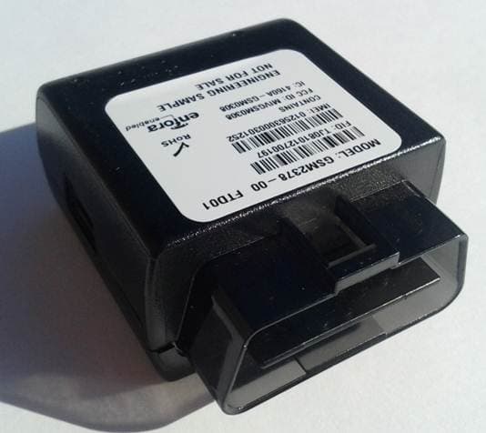
MIVRTT2211
Jan 22, 2013CDMA Licensed Transmitter
Equipment Class
PCB - PCS Licensed Transmitter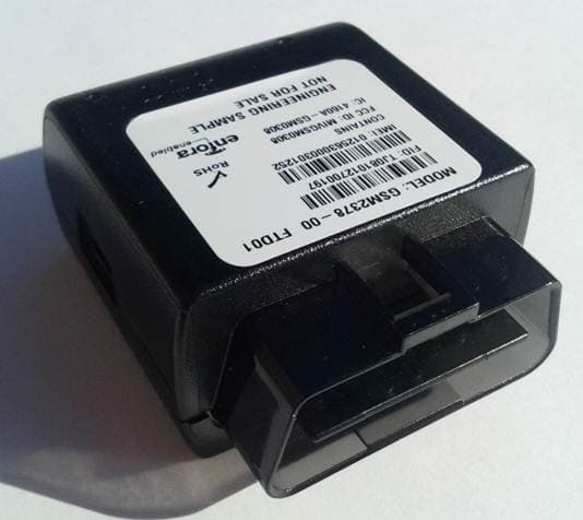
MIVGSM2378
Dec 23, 2012PCS GSM/ GPRS Licensed Transmitter
Equipment Class
PCB - PCS Licensed Transmitter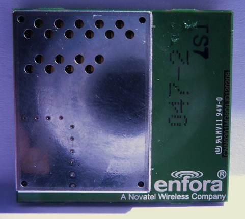
MIVCNN0301
May 10, 20121XRTT Multi-Band M2M OEM Module
Equipment Class
PCB - PCS Licensed Transmitter
MIVGSM2428
Jun 15, 2011GSM/ GPRS Personal Tracker
Equipment Class
JBP - Part 15 Class B Computing Device Peripheral
MIVGSM5218
Mar 15, 2011GSM/GPRS Asset Tracker
Equipment Class
PCB - PCS Licensed Transmitter