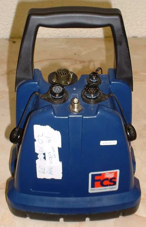
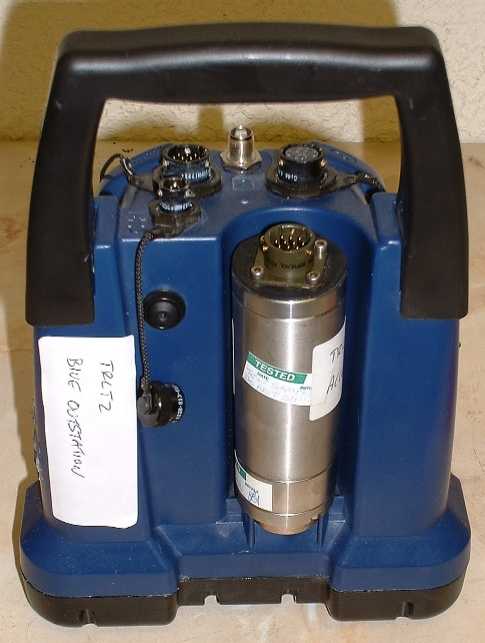
MJCMDMicroCorr Digital Leak Detector Out-Station
Palmer Environmental Ltd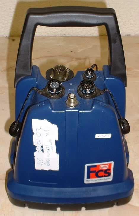
Click to zoom
Application Details
- Equipment Class
- TNB - Licensed Non-Broadcast Station Transmitter
- Date of Grant
- Jan 23, 2005
- Application Purpose
- Original Equipment
- Date of Application
- Jan 23, 2005
- Equipment Note
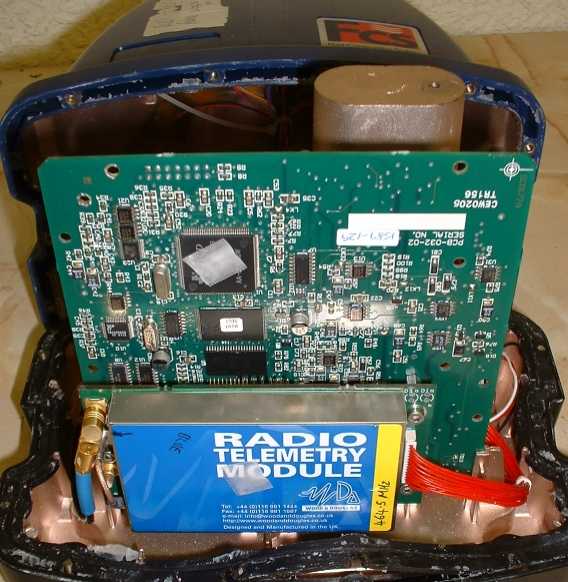
- MicroCorr Digital Leak Detector Out-Station
- Frequency Range
- 464.49500000 - 464.50500000
- Company
- Palmer Environmental Ltd
- Country
- United Kingdom
Documents & Files
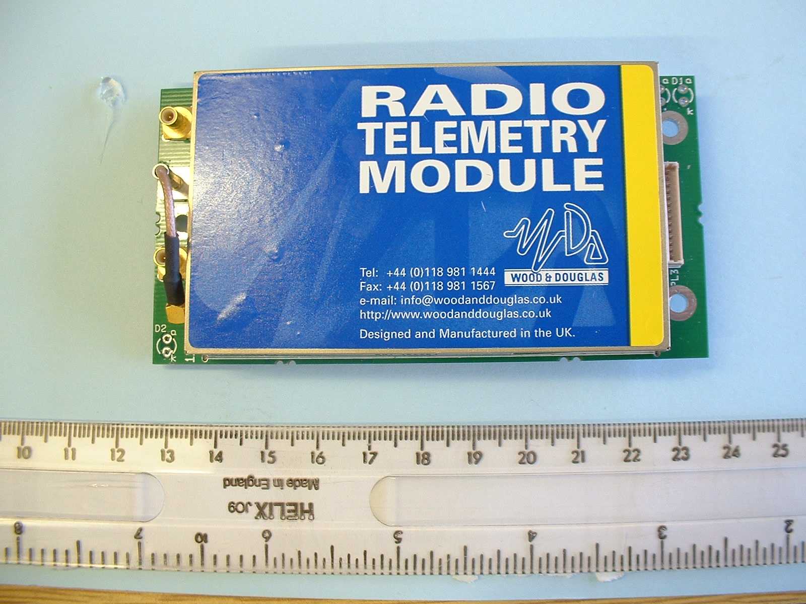
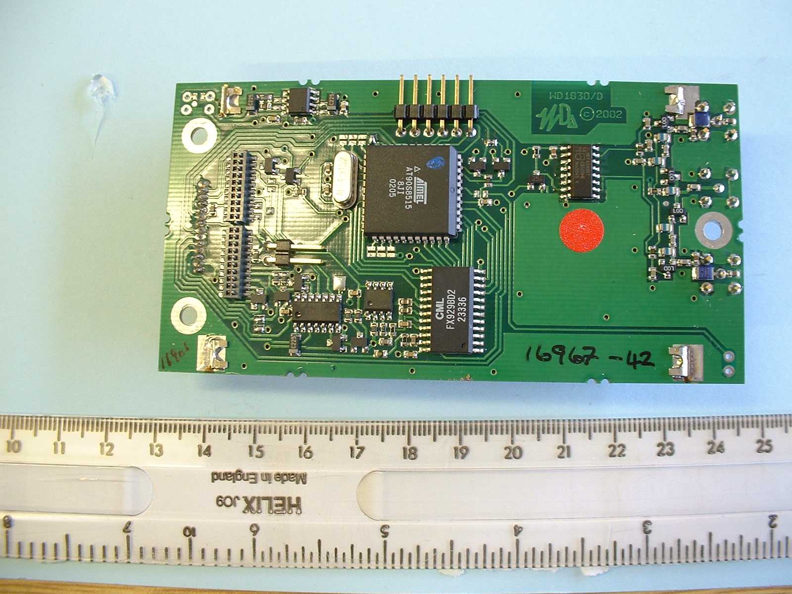
Document Text
Text extracted from the exhibit documents filed with the FCC. Open a document above to read the original.
Users Manual
1 MicroCorr Digital Users Guide Ty Coch House Llantarnam Park Way Cwmbran NP44 3AW United Kingdom Tel: +44 (0) 1633 489479 Fax: +44 (0) 1633 877857 Email: [email protected] Internet: www.palmer.co.uk Mcorr Dig UG Issue 5bAugust 2003 Based on SW-042-01-109a Based on FW-042-02-107a 2 MicroCorr Digital Users Guide Introduction and Features.......................................................................................................... 3 New features.............................................................................................................................. 3 Operational Benefits .................................................................................................................. 4 Principle of Correlation .............................................................................................................. 5 System Overview....................................................................................................................... 6 Standard system configuration ..................................................................................................6 Optional accessories ................................................................................................................. 6 Fully Digital Correlation ............................................................................................................. 7 Features of the correlator unit ................................................................................................... 8 Features of the Out Stations...................................................................................................... 9 MicroCorr ® DIGITAL correlator unit operational features ........................................................ 11 Key functions ........................................................................................................................... 11 Using the MicroCorr Digital Correlator................................................................................... 12 BATTERY WARNING.............................................................................................................. 12 Step 1: Charging and installing batteries................................................................................ 12 Step 2: Set up and deployment of Out Stations ..................................................................... 14 Step 3: Switching on the Correlator........................................................................................ 15 Correlating ............................................................................................................................... 16 Main Menu ............................................................................................................................... 17 Correlate ..................................................................................................................... 17 File .............................................................................................................................. 17 Regression Analysis ................................................................................................... 19 Set-up .........................................................................................................................22 Test and Service......................................................................................................... 24 Other System Options ................................................................................................ 26 Correlation Screen................................................................................................................... 27 Pipe data..................................................................................................................... 28 Zoom...........................................................................................................................32 Peak Suppression Screen .......................................................................................... 33 View Settings .............................................................................................................. 34 Calculate Velocity ....................................................................................................... 35 Filters ....................................................................................................................................... 37 Program upgrade (Software and Firmware) ............................................................................ 40 Technical Specification ............................................................................................................ 43 Warranty .................................................................................................................................. 45 Patents..................................................................................................................................... 45 3 MicroCorr Digital Users Guide Introduction and Features MicroCorr ® DIGITAL is the latest model of the world’s leading correlator brand (over 4,000 MicroCorr ® units in use worldwide) but is the first fully digital system. This enables it to achieve performance levels well in excess of previous analogue-based systems, with important benefits to the user. • Totally digital system • Superior leak detection performance on all pipe materials and sizes • Quick and easy to use, especially for less experienced operators • Automatic parametric filtering (APF) • Ergonomically designed – lightweight, compact system • 1/4 VGA colour display • Software upgrades via Internet web site • Optional third Out Station for velocity measurement and rapid survey • Select dedicated or PC-based models New features • Transceiver communication enables all system functions to be controlled centrally, enabling quicker deployment • Expert s…
Text truncated - open the document above for the full version.
Users Manual
21 Press 2 (Remove / Restore) Allows you to select a suspicious correlation for removal. After pressing 2, use the arrow keys to select the cross on the regression graph for removal (a box appears around the selected cross) then press ENTER. Press 3 (Load data) Retrieves previously stored regression analysis graph results. Press 4 (Save data) Saves the current regression analysis graph results. Press 5 (Delete) Enables the deletion of saved regression analysis files. Press 6 (Information) Displays correlation information. After pressing 6, use the arrow keys to select the cross on the regression graph for information to be displayed (a box appears around the selected cross) then press ENTER Press 7 (Remove all data) Removes all data currently being used on the regression graph, you will be prompted to verify your selection. Press 8 (Static sensor) Allows you to change the colour of the static sensor. 22 Set-up Press 1(Correlate on start-up) Toggles between YES and NO. If set to YES, the control unit will go straight to the correlate screen after turning on. If set to NO, the control unit will go straight to the Main Menu after turning on. Press 2(Default filters) Toggles between CLEAR and RETAIN. If set to CLEAR, in survey mode, the filters will clear each time a new correlation is processed. If set to RETAIN, in survey mode, the filters will retain a set filter setting (set by the user) for every correlation processed. Press 3(Survey mode range) Toggles between 0.8, 2.4 and 4.0 seconds. Each of these values provides the time delay range over which the correlator will correlate, where the times in seconds shows twice the range. For example, over longer distances the 4.0 second range should be used to give +2 seconds to –2 seconds. If entering pipe data, the survey mode range automatically defaults to the appropriate setting. Press 4(Correlation sensors) Toggles between the pairs of sensors to be used. Red-Blue, Red-Yellow, Blue-Yellow, Base-Red, Base-Blue and Base-Yellow. Press 5(Radio Mode) Toggles between HIGH power and LOW power. LOW power can be used over shorter distances and HIGH power over longer distances or areas where a signal can be interrupted by the environment. The correlator will always default to LOW power when turning on. 23 Press 6(Power Saving) Press 1 to toggle the System power off between NEVER and 5, 10, 15, 20, 25, 30, 35, 40, 45, 50, 55 and 60 minutes duration. Press 2 to toggle the Backlight off between NEVER and 5, 10, 15, 20, 25, 30, 35, 40, 45, 50, 55 and 60 minutes duration. Press 7(Display set-up) Press 1 to incrementally decrease the screen brightness. Press 2 to incrementally increase the screen brightness. Press 3 to incrementally decrease the screen contrast. Press 4 to incrementally increase the screen contrast. Press 8(Control beacons) Press 1 to switch On the flashing beacons on the transmitters. Press 2 to switch Off the flashing beacons on the transmitters. Note. The beacons should be checked when switched on from the control unit as they will only switch on if they are within range to pick up the signal. 24 Test and Service Press 1(Restore default pipe data) Wait a few seconds and the default pipe data will be restored to the control unit. Press 2(Units are Metric) Toggle between METRIC and IMPERIAL measurement units. Press 3(Time is in milliseconds) Toggles between MILLISECONDS and SECONDS Press 4(Using HP printer) Toggle between HP and EPSON printer. Press 5(Language) Select the required language by using the arrow buttons. 25 Press 6(Set clock) Set the clock according to the user preferred format. Press 7(Debug Messages are Off) Toggles between ON and OFF. This should normally be set to OFF and is normally only used during fault diagnosis. Press 8(Information) Connect sensors to Out Stations and turn on before pressing 8. This displays the current firmware and software version currently installed on the MC Digital. 26 Press 9(Diagnostics) Displays a series of numbers. This is only used during fault diagnosis Other System Options The MC Digital is designed for versatility. Pressing 1 will activate the Permalog Patroller Link, changing the MC Digital into a Permalog Patroller. (This is only possible if the Patroller Link radio has been purchased, not fitted as standard) 27 Correlation Screen A dashed cursor line shows the position of the largest peak (best result). The dashed cursor line can be moved once the correlation has been stopped, by using the arrow keys. Moving the dashed cursor line alters the correlation distance. This screen shows the result of a correlation where the position of the leak is. In this example 63.4 metres from the Red Out Station and 60.6 metres from the Blue Out Station. The time delay is calculated at 2.3 milliseconds. The correlation shown has a SNR of 29:1. Signal to Noise Ratio (SNR) means the largest correlation peak is 29x larger than any other displayed peak shown on the correlation graph. Hence the larger the SNR the more pronounced the peak will be. Press 1(Listen) Attach the headphones to the control unit before pressing 1. Use the arrow keys to select the sensor required to listen to; BASE, RED, BLUE or YELLOW. The sound will transmit in blocks of approx 20 seconds. To stop listening press ENTER, but note the sound will continue until the 20 seconds elapses. 28 Pipe data Press 2(Pipe data) To accurately locate a leak position the user must enter the correct information with respect to the physical properties of the pipe. Each section must be entered to be accepted by the system. Press 5 to Add new pipe data. A default setting appears. 29 Press 1 to enter Length, the distance between the sensors. In this example 124m. Press 2 to enter material type, use the arrow keys to select the required pipe material and press ENTER. In this example cast iron is selected. 30 Press 3 to enter the diameter of the pipe. In this example 80mm. The velocity column will then automatically be updated. In this example 1.280 m/ms. T…
Text truncated - open the document above for the full version.
Attestation Statements
Palmer Environmental Ltd. Registered in England. Registration No. 1463016 Letter of Agency 5 th February 04 To Whom It May Concern: We certify that we are not subject to denial of federal benefits, that includes FCC benefits, pursuant to Section 5301 of the Anti-Drug Abuse ACT of 1988, U.S.C. 862. Further, no party, as defined in 47 CFR 1.2002(b), to the application is subject to denial of federal benefits, that includes FCC benefits. Thank you for your attention to this matter. Yours faithfully Simon Harris Product Support Manager On Behalf of Palmer Environmental Ltd. Ty Coch House Llantarnam Park Way Cwmbran NP44 3AW United Kingdom Tel: +44 (0) 1633 489479 Fax: +44 (0) 1633 877857 Email: [email protected] Web: www.palmer.co.uk
Cover Letter(s)
Palmer Environmental Ltd. Registered in England. Registration No. 1463016 Request for Confidentiality 05/02/04 TRL Compliance Services Ltd Long Green Forthampton Gloucester GL19 4QH UK RE: Certification Application FCC ID: MJCMCD To Whom It May Concern: Please be advised that the following information is to be held confidential on behalf of Palmer Environmental Ltd. • SE-032-001-A Kestrel DSP+CPU & Mem.PDF • SE-032-002-A DSP Digital Interface.PDF • SE-032-003-A DSP Analogue Interface.PDF • SE-032-004-A DSP Power Supplies.PDF • SE-032-005-A DSP External Power.PDF • SE-042-03-Kestrel Keypad PCB.pdf • DOC-042-0001KESTRAL BLOCK DIAGRAM.PDF • GP-042-0003-F Basestation Core Assy.xls • GP-042-0008-A MCD Outstation Kit FCS Red.xls • GP-042-0009-A MCD Outstation Kit FCS Blue.xls • GP-042-0017-A Top Level Kit 2 Outstation FCS.xls • GP-042-0018-B Basestation Kit Hitachi FCS.xls • GP-042-0020-E MCD Outstation Core Assy.xls • GP-042-0025-A Pelican Case Core Assy.xls • GP-042-0028-A MCD Family Tree 2 Outstation FCS.doc • DOC-042-0002MCD Technical Description.doc The application contains technical information which Palmer Environmental Ltd. deems to be trade secrets and proprietary. If made public, the information might be used to the disadvantage of the applicant in the market place. Thank you for your attention to this matter. Yours faithfully Simon Harris Product Support Manager On Behalf of Palmer Environmental Ltd. Ty Coch House Llantarnam Park Way Cwmbran NP44 3AW United Kingdom Tel: +44 (0) 1633 489479 Fax: +44 (0) 1633 877857 Email: [email protected] Web: www.palmer.co.uk
Test Report
TRL C OMPLIANCE S ERVICES L TD EMC D IVISION L ONG G REEN F ORTHAMPTON G LOUCESTER GL19 4QH U NITED K INGDOM T ELEPHONE +44 (0)1684 833818 F AX +44 (0)1684 833858 E- MAIL [email protected] www.trlcompliance.com TEST REPORT NO: RU1017/4145 COPY NO: 2 ISSUE NO: 1 FCC ID: MJCMD REPORT ON THE CERTIFICATION TESTING OF A PALMER ENVIRONMENTAL Ltd MICROCORR DIGITAL OUTSTATION WITH RESPECT TO THE FCC RULES CFR 47, PART 90 INTENTIONAL RADIATOR SPECIFICATION ON BEHALF OF PALMER ENVIRONMENTAL Ltd TEST DATE: 25 th – 30 th November 2002 TESTED BY: J CHARTERS APPROVED BY: P GREEN PRODUCT MANAGER DATE: 28 th November 2004 Distribution: Copy Nos: 1. PALMER ENVIRONMENTAL Ltd 2. FCC EVALUATION LABORATORIES 3. TRL EMC THIS DOCUMENT MAY BE REPRODUCED ONLY IN ITS ENTIRETY AND WITHOUT CHANGE RU1017/4145 Page 2 of 35 CONTENTS PAGE CERTIFICATE OF CONFORMITY & COMPLIANCE 3 APPLICANT’S SUMMARY 4 EQUIPMENT TEST CONDITIONS 5 TESTS REQUIRED 5 TEST RESULTS 6-24 ANNEX PHOTOGRAPHS A PHOTOGRAPH No. 1: Test setup PHOTOGRAPH No. 2: Transmitter front view PHOTOGRAPH No. 3: Transmitter rear view PHOTOGRAPH No. 4: PCB track side PHOTOGRAPH No. 5: Transmitter module PHOTOGRAPH No. 6: Transmitter module PHOTOGRAPH No. 7: EQUIPMENT UNDER TEST APPLICANT’S SUBMISSION OF DOCUMENTATION LIST B BAND OCCUPANCY PLOT C Notes: 1. Component failure during test YES NO [ ] [X] 2. If Yes, details of failure: 3. The facilities used for the testing of the product contain in this report are FCC Listed. 4. The contents of the attached applicants declarations and other supplied information are not covered by the scope of this laboratory’s UKAS or FCC accreditations’ and is provided in good faith. RU1017/4145 Page 3 of 35 CERTIFICATE OF CONFORMITY & COMPLIANCE FCC IDENTITY: MJCMD PURPOSE OF TEST: CERTIFICATION TEST SPECIFICATION: FCC RULES CFR 47, Part 90 TEST RESULT: Compliant to Specification EQUIPMENT UNDER TEST: MICROCORR DIGITAL OUTSTATION EQUIPMENT SERIAL No: Engineering Sample ITU: EMISSION CODE: 16k2F2D EQUIPMENT TYPE: OUTSTATION PRODUCT USE: Water Leak Detection CARRIER EMISSION: High Power 24.3dBm Low Power 5.0dBm ANTENNA TYPE: Whip ALTERNATIVE ANTENNA: Not applicable FREQUENCY OF OPERATION: 464.5MHz CHANNEL SPACING: 25kHz NUMBER OF CHANNELS: 1 FREQUENCY GENERATION: SAW Resonator [ ] Crystal [ ] Synthesiser [X] MODULATION METHOD: Amplitude [ ] Digital [X] Angle [ ] POWER SOURCE(s): 12Vdc Battery TEST DATE(s): 25 th – 30 th November 2002 ORDER No(s): 29217 APPLICANT: PALMER ENVIRONMENTAL Ltd ADDRESS: TY-COCH HOUSE LLANTARNAM PARK WAY CWMBRAN NP44 3AW UNITED KINGDOM TESTED BY: J CHARTERS APPROVED BY: P GREEN PRODUCT MANAGER RU1017/4145 Page 4 of 35 APPLICANT’S SUMMARY EQUIPMENT UNDER TEST (EUT): MICROCORR DIGITAL OUTSTATION EQUIPMENT TYPE: OUTSTATION SERIAL NUMBER OF EUT: Engineering Sample PURPOSE OF TEST: CERTIFICATION TEST SPECIFICATION(s): FCC RULES CFR 47, Part 90 TEST RESULT: COMPLIANT Yes No [X] [ ] APPLICANT’S CATEGORY: MANUFACTURER IMPORTER DISTRIBUTOR TEST HOUSE AGENT [X] [ ] [ ] [ ] [ ] APPLICANT’S ORDER No(s): 29217 APPLICANT’S CONTACT PERSON(s): Mr S Harris E-mail address: [email protected] APPLICANT: PALMER ENVIRONMENTAL Ltd ADDRESS: TY-COCH HOUSE LLANTARNAM PARK WAY CWMBRAN NP44 3AW UNITED KINGDOM TEL: +44 (0)1633 489479 FAX: +44 (0)1633 877857 MANUFACTURER: PALMER ENVIRONMENTAL Ltd EUT(s) COUNTRY OF ORIGIN: UNITED KINGDOM TEST LABORATORY: TRL EMC UKAS ACCREDITATION No: 0728 TEST DATE(s) 25 th – 30 th November 2004 TEST REPORT No: RU1017/4145 RU1017/4145 Page 5 of 35 EQUIPMENT TEST / EXAMINATIONS REQUIRED 1. TEST/EXAMINATION RULE PART DETECTOR APPLICABILITY RF Power Output: 90.2052 Peak Yes Modulation Limits: 90.212 Peak Yes Occupied Bandwidth: 90.209 Peak Yes Spurious Emissions at Antenna Terminal: 2.991 Quasi Peak Average Yes Field Strength of Spurious Radiation: 90.210 Quasi Peak Average Yes Frequency Stability: 90.213 Peak Yes Transient Frequency Behaviour: 90.214 N/A Yes Maximum Frequency of Search: - Yes 2. Product Use: Leak detection 3. Emission Designator: 16k2F2D 4. Duty Cycle: <100% 5. Temperatures: Ambient (Tnom) 19 o C 6. Supply Voltages: Vnom 7.5Vdc Note: Vnom voltages are as stated above unless otherwise shown on the test report page Single channel [X] Two channel [ ] 7. Equipment Category: Multi-channel [ ] Narrowband [X] Wideband [ ] 8. Channel spacing: 25kHz RU1017/4145 Page 6 of 35 TRANSMITTER OUTPUT POWER – CONDUCTED – PART 2.1046 Ambient temperature = 18 o C Supply voltage = 12Vdc Relative humidity = 70% Channel number = 464.5MHz See Annex C for full list of test equipment The test setup was as per the above diagram .The unit was put into test mode and set to operate at both power modes. RESULTS Microcore Digital Outstation was found to comply with the limits. FREQ. (MHz) MEASURED VALUE (dBm) CABLE LOSS (dB) ATENUATOR (dBm) LEVEL (dBm) LEVEL (WATTS) 464.5 -5.9 0.2 30 24.3 0.269 464.5 5.0 0.2 0 5.2 0.004 Notes: 1 Results quoted are extrapolated as indicated 2 Test at both high and low power 3 New batteries used for battery powered products TRLUH120 TRLUH179 EUT RU1017/4145 Page 7 of 35 TRANSMITTER TESTS TRANSMITTER OCCUPIED BANDWIDTH – CONDUCTED – PART 2.1049(1) Ambient temperature = 18 o C Supply voltage = 12Vdc Relative humidity = 70% Channel number = 464.5MHz ITU emission code = 16k6F2D Authorised Bandwidth = 20kHz See Annex C for full list of test equipment The test setup was as per the above diagram. The unit was put into test mode and set to operate at maximum power. . On any frequency removed from the assigned frequency by the following percentage of the authorised bandwidth Frequency Applicable level Frequency (MHz) Frequency (MHz) Level dBc High power Level dBc Low power Result ABW ±5kHz 0 464.495 464.505 0 0 Compliant >5kHz<10kHz f d 83log(f d /5) 464.49 464.51 -24.9 -24.9 Compliant f d >10kHz <250% 29log (f d 2 /11)dB or 50dB 464.45 464.55 -50.0 -50.0 Compliant Limits Emission Mask C >250% 43+10log(P)dB 464.45< 464.55> -56.9 -50.1 Compliant Notes: 1 ABW =Authorized bandwidth P = Carrier o…
Text truncated - open the document above for the full version.
Test Setup Photos
RF335 iss02 RU1017/4145 Page 31 of 35 PHOTOGRAPH No. 6 EQUIPMENT UNDER TEST
Contact Information
Applicant
Dean Aronld
Technical Contact
Palmer Environmental LtdSimon Harris
[email protected]+44 1633 489479
Ty Coch House, Llantarnam Park Way · Cwmbran, Gwent · United Kingdom
Test Firm
TRL EMC LimitedNeil Roche
Technical Specifications
| # | Rule Parts | Frequency Range | Power Output | Emission | Tolerance |
|---|---|---|---|---|---|
| 1 | 90 | 464.495 MHz - 464.505 MHz | 500.00 mW | 16K0F3D | 900.0000000000 Hz |
Other Applications from Palmer Environmental Ltd
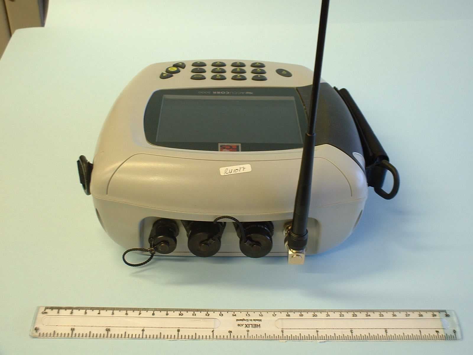
MJCMCD
Jan 23, 2005MicroCorr Digital Leak Detector Base Station
Equipment Class
TNB - Licensed Non-Broadcast Station Transmitter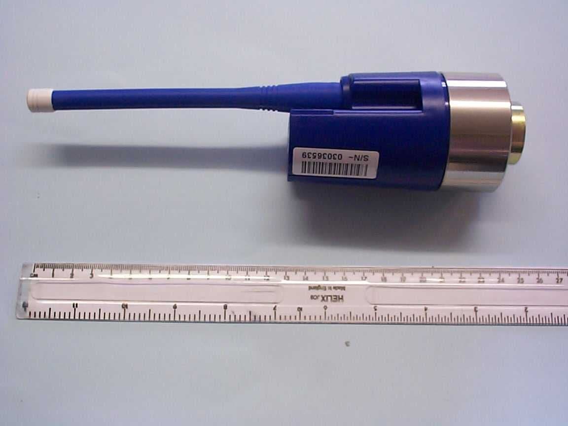
MJCP3
May 12, 2004Permalog 3
Equipment Class
TNB - Licensed Non-Broadcast Station Transmitter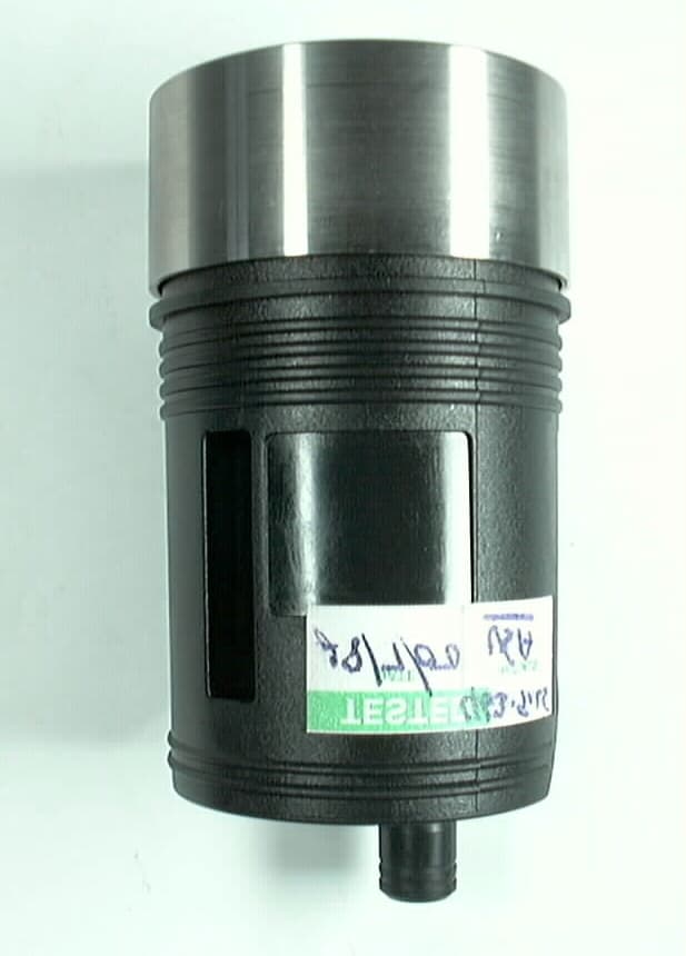
MJCPERMALOGII
Apr 25, 2001Permalog Logger II
Equipment Class
TNB - Licensed Non-Broadcast Station Transmitter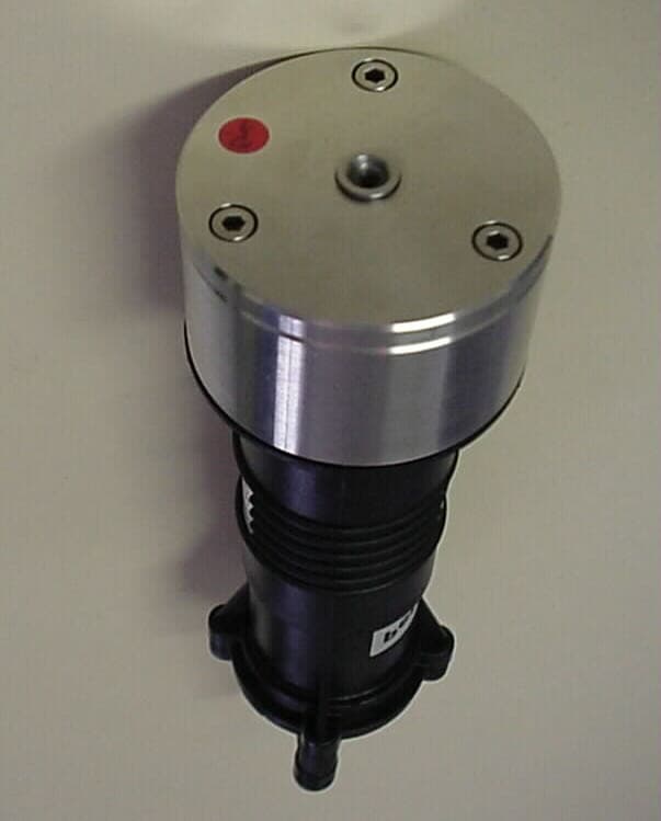
MJCPERMALOG
Dec 26, 2000Permalog Logger I
Equipment Class
TNB - Licensed Non-Broadcast Station TransmitterMJCPT2
Dec 04, 1995TNB - Licensed Non-Broadcast Station Transmitter
Equipment Class
TNB - Licensed Non-Broadcast Station Transmitter