MLBHLIK-1RPart 15 Security - Remote control transmitter
Honda Lock Mfg. Co., Ltd.
Click to zoom
Application Details
- Equipment Class
- CYY - Communications Receiver used w/Pt 15 Transmitter
- Date of Grant
- May 02, 2006
- Application Purpose
- Original Equipment
- Date of Application
- Apr 15, 2006
- Equipment Note
- Part 15 Security - Remote control transmitter
- Frequency Range
- 313.85000000 - 313.85000000
- Company
- Honda Lock Mfg. Co., Ltd.
- Country
- Japan
Documents & Files
Document Text
Text extracted from the exhibit documents filed with the FCC. Open a document above to read the original.
Users Manual
As required by the FCC: This device complies with Part 15 of the FCC rules. Operation is subject to the following two conditions: (1) This device may not cause harmful interference, and (2) this device must accept any interference received, including interference that may cause undesired operation. Changes or modifications not expressly approved by the party responsible for compliance could void the user’s authority to operate the equipment. This device complies with Industry Canada Standard RSS-210. Operation is subject to the following two conditions: (1) this device may not cause interference, and (2) this device must accept any interference that may cause undesired operation of the device. The immobilizer system protects your vehicle from theft. If an improperly-coded key (or other device) is used, the engine’s fuel system is disabled. The system may not recognize your key’s coding if another immobilizer key or other metal object (i.e. key fob) is near the ignition switch when you insert the key. If the system repeatedly does not recognize the coding of your key, contact your dealer. Do not attempt to alter this system or add other devices to it. Electrical problems could result that may make your vehicle undriveable. If you have lost your key and cannot start your engine, contact your dealer. When you turn the ignition switch to the ON (II) position, the immobilizer system indicator should come on briefly, then go off. If the indicator starts to blink, it means the system does not recognize the coding of the key. Turn the ignition switch to the LOCK (0) position, remove the key, reinsert it, and turn the ignition switch to the ON (II) position again. Immobilizer System 76 Remove the old battery from the back of the inner cover, and insert a new battery into the back of the cover with theside facing down. Install the parts in reverse order. An improperly disposed battery can hurt the environment. Always confirm local regulations for battery disposal. 4. 5. Keyless Entry Function When using radio equipment with very small output capacity, the equipment must accept any interference caused by the emission of various radio communication equipment as well as industrial, scientific and medical facilities. Use of such radio equipment is prohibited in an aeroplane and around an airport. Modulation Mode: FSK Frequency Range: 313 314 MHz Transmitting Power:6000V/m (3 m) Occupied Bandwith:300 kHz Spurious Emission Limits:600V/m (3 m) The equipment shall not cause any harmful interference with various authorized radio communication. If such interference is detected, operation of the equipment shall be suspended until a measure is taken to remove such interference. The user shall not change the transmission frequency, amplify the output capacity by such means as installing a transmission amplifier, install another aerial, or replace the original transmission aerial without permission of the Authority. Instruments and Controls Remote Transmitter Chinese Regulations f or Controlling Short Range Radio Equipment 84 06/03/20 16:43:07 32SDRT00_089 Inside the transmitter, separate the inner cover from the keypad by releasing the two tabs on the cover. Remove the old battery from the back of the inner cover, and note the polarity. Make sure the polarity of the new battery is the same (side facing down), then insert it into the back of the cover. Install the parts in reverse order. 3. 4. 5. As required by the FCC: This device complies with Part 15 of the FCC rules. Operation is subject to the following two conditions: (1) This device may not cause harmful interference, and (2) this device must accept any interference received, including interference that may cause undesired operation. Changes or modifications not expressly approved by the party responsible for compliance could void the user’s authority to operate the equipment. This device complies with Industry Canada Standard RSS-210. Operation is subject to the following two conditions: (1) this device may not cause interference, and (2) this device must accept any interference that may cause undesired operation of the device. Remote Transmitter Instruments and Controls 87 TAB BATTERY
External Photos
Honda Lock Mfg Co., Ltd. System: Integrate Immobilizer System with RKE Product: Receiver of Keyless system FCC ID: MLBHLIK-1R IC: 2500A-HLIK1R External Photo Side A Side B
ID Label/Location Info
The Attachment Position of Label Label form details FCC ID : MLBHLIK-1R IC : 2500A-HLIK1R MODEL NO. : HLIK-1R Label: Material : Resin Laser Marking Control Unit Serial number
Internal Photos
Honda Lock Mfg Co., Ltd. System: Integrate Immobilizer System with RKE Product: Receiver of Keyless system FCC ID: MLBHLIK-1R IC: 2500A-HLIK1R Internal Photo Side A Side B Honda Lock Mfg Co., Ltd. System: Integrate Immobilizer System with RKE Product: Receiver of Keyless system FCC ID: MLBHLIK-1R IC: 2500A-HLIK1R ANTENNA Keyless Antenna Keyless Antenna Keyless Antenna Keyless Antenna
Test Report
Test report No. : 26DE0207-HO-3 Page : 2 of 12 Issued date : February 28, 2006 FCC ID : MLBHLIK-1R UL Apex Co., Ltd. Head Office EMC Lab. 4383-326 Asama-cho, Ise-shi, Mie-ken 516-0021 JAPAN Telephone : +81 596 24 8116 Facsimile : +81 596 24 8124 MF060b(01.06.05) CONTENTS PAGE SECTION 1: Client information............................................................................................. 3 SECTION 2: Equipment under test (E.U.T.) ........................................................................ 3 SECTION 3: Test specification, procedures & results ......................................................... 4 SECTION 4: Operation of E.U.T. during testing.................................................................. 6 SECTION 6: Radiated Emission ............................................................................................ 7 APPENDIX 1: Photographs of test setup............................................................................... 8 Radiated Emission ......................................................................................................................... 8 Worst Case Position....................................................................................................................... 9 APPENDIX 2: Test instruments ........................................................................................... 10 APPENDIX 3: Data of EMI test ........................................................................................... 11 Radiated Emission ....................................................................................................................... 11 Test report No. : 26DE0207-HO-3 Page : 3 of 12 Issued date : February 28, 2006 FCC ID : MLBHLIK-1R UL Apex Co., Ltd. Head Office EMC Lab. 4383-326 Asama-cho, Ise-shi, Mie-ken 516-0021 JAPAN Telephone : +81 596 24 8116 Facsimile : +81 596 24 8124 MF060b(01.06.05) SECTION 1: Client information Company Name : Honda Lock Mfg. Co., Ltd. Address : 535-14 Oaza-Ishizue, Takanezawamachi, Shioya-Gun, Tochigi, 329-1225 Japan Telephone Number : +81-28-680-1661 Facsimile Number : +81-28-680-1045 Contact Person : Mitsunori Suyama SECTION 2: Equipment under test (E.U.T.) 2.1 Identification of E.U.T. Type of Equipment : System: Integrate Immobilizer system with RKE Product: Receiver of Keyless system Model No. : System: HLIK-1 Product: HLIK-1R Serial No. : 0005 Country of Manufacture : Japan Receipt Date of Sample : January 26, 2006 Condition of EUT : Production prototype (Not for Sale: This sample is equivalent to mass-produced items.) 2.2 Product Description Model No: HLIK-1R (referred to as the EUT in this report) is the Receiver of Keyless system. Equipment Type : Transceiver Power Supply : DC12.0V Operating Voltage : DC5.0V [Tx section] *1) Frequency of Operation : 125kHz Type of modulation : ASK Mode of Operation : Simplex Antenna Type : Loop Antenna Mehod of Frequency Generation : Ceramic Resonator [Rx section] Receiving frequency : 313.85MHz Antenna Type : Monopole Antenna *1) Please refer to UL Apex Test Report No. 26DE0207-HO-2 for Tx section test (FCC 15 Subpart C test) Test report No. : 26DE0207-HO-3 Page : 4 of 12 Issued date : February 28, 2006 FCC ID : MLBHLIK-1R UL Apex Co., Ltd. Head Office EMC Lab. 4383-326 Asama-cho, Ise-shi, Mie-ken 516-0021 JAPAN Telephone : +81 596 24 8116 Facsimile : +81 596 24 8124 MF060b(01.06.05) SECTION 3: Test specification, procedures & results 3.1 Test specification Test Specification : FCC Part 15 Subpart B 2006 Title : FCC 47CFR Part15 Radio Frequency Device Subpart B Unintentional Radiators FCC 15.111(b) The receiving antenna is installed inside the EUT and cannot be removed. Therefore, the EUT complies with the requirement in section 15.111(b). 3.2 Procedures and results Item Test Procedure Limits Deviation Worst margin *0) Result Conducted emission ANSI C63.4: 2003 7. AC powerline conducted emission measurements Class B N/A*1) N/A Complied Radiated emission ANSI C63.4: 2003 8. Radiated emission measurements Class B N/A 22.3dB 376.270MHz Horizontal Complied *Note: UL Apex’s EMI Work Procedure QPM05. *0) The result is rounded off to the second decimal place. Therefore, there may be 0.1 difference for the result. *1) The test is not applicable since the EUT does not have AC power port. *These tests were performed without any deviations from test procedure except for additions or exclusions. 3.3 Additions or deviations to standards No addition, deviation, nor exclusion has been made from standards. 3.4 Confirmation UL Apex Co., Ltd. hereby confirms that E.U.T., in the configuration tested, complies with the specifications, FCC Part15 Subpart B 2006. Test report No. : 26DE0207-HO-3 Page : 5 of 12 Issued date : February 28, 2006 FCC ID : MLBHLIK-1R UL Apex Co., Ltd. Head Office EMC Lab. 4383-326 Asama-cho, Ise-shi, Mie-ken 516-0021 JAPAN Telephone : +81 596 24 8116 Facsimile : +81 596 24 8124 MF060b(01.06.05) 3.5 Uncertainty Radiated Emission The measurement uncertainty (with a 95% confidence level) for this test using Biconical antenna is ±4.5dB(3m). The measurement uncertainty (with a 95% confidence level) for this test using Logperiodic antenna is ±5.2dB(3m). The measurement uncertainty (with a 95% confidence level) for this test using Horn antenna is ±6.6dB. The data listed in this test report has enough margin, more than the site margin. 3.6 Test Location UL Apex Co., Ltd. Head Office EMC Lab. *NVLAP Lab. code: 200572-0 4383-326 Asama-cho, Ise-shi, Mie-ken 516-0021 JAPAN Telephone : +81 596 24 8116 Facsimile : +81 596 24 8124 FCC Registration Number IC Number Width x Depth x Height (m) Size of reference ground plane / horizontal conducting plane (m) Other rooms No.1 semi-anechoic chamber 313583 IC4247A 19.2 x 11.2 x 7.7m 7.0 x 6.0m Preparation room No.2 semi-anechoic chamber 846015 IC4247A-2 7.5 x 5.8 x 5.2m 4.0 x 4.0m - No.3 shielded room - - 4.7 x 7.5 x 2.7m 4.7 x 7.5m - No.4 measurement room - - 3.1 x 5.0 x 2.7m N/A - * Siz…
Text truncated - open the document above for the full version.
Test Setup Photos
Test report No. : 26DE0207-HO-3 Page : 8 of 12 Issued date : February 28, 2006 FCC ID : MLBHLIK-1R UL Apex Co., Ltd. Head Office EMC Lab. 4383-326 Asama-cho, Ise-shi, Mie-ken 516-0021 JAPAN Telephone : +81 596 24 8116 Facsimile : +81 596 24 8124 MF060b(01.06.05) APPENDIX 1: Photographs of test setup Radiated Emission Front Rear Test report No. : 26DE0207-HO-3 Page : 9 of 12 Issued date : February 28, 2006 FCC ID : MLBHLIK-1R UL Apex Co., Ltd. Head Office EMC Lab. 4383-326 Asama-cho, Ise-shi, Mie-ken 516-0021 JAPAN Telephone : +81 596 24 8116 Facsimile : +81 596 24 8124 MF060b(01.06.05) Worst Case Position (Horizontal :Y-axis / Vertical :Y-axis) X-axis Y-axis Z-axis
Contact Information
Applicant
Yoshinari Tamada(Manager)
Technical Contact
UL Apex Co LtdNaoki Sakamoto
[email protected]+81 596 24 8116
4383-325 Asama-Cho · Ise-Shi, Mie-Ken · Japan
Non-Technical Contact
UL Apex Co LtdNaoki Sakamoto
[email protected]+81 596 24 8116
Test Firm
UL Japan, IncMitsuru Fujimura
Technical Specifications
| # | Rule Parts | Frequency Range | Power Output |
|---|---|---|---|
| 1 | 15B | 313.85 MHz - 313.85 MHz | - |
Other Applications from Honda Lock Mfg. Co., Ltd.
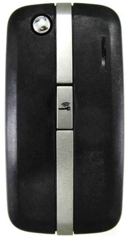
MLBHLSS-5B
Feb 16, 2020FOB OF 2R SMART SYSTEM
Equipment Class
DSC - Part 15 Security/Remote Control Transmitter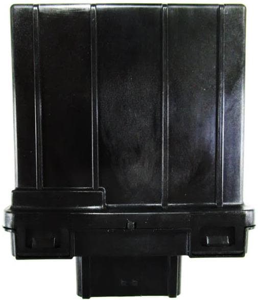
MLBHLSS-5A
Feb 16, 2020ECU of 2R SMART SYSTEM
Equipment Class
CYY - Communications Receiver used w/Pt 15 Transmitter
MLBHLSS-3A
Aug 30, 20152R Smart Key system(ECU)
Equipment Class
DCD - Part 15 Low Power Transmitter Below 1705 kHz
MLBHLSS-3B
Aug 18, 20152R Smart Key system(FOB)
Equipment Class
DSC - Part 15 Security/Remote Control Transmitter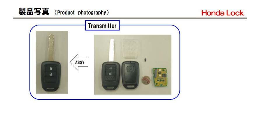
MLBHLIK6-1TA
Oct 28, 2014Keyless transmitter
Equipment Class
DSC - Part 15 Security/Remote Control Transmitter