MMFTH208-W1TH208-W1
Sato Corporation
Click to zoom
Application Details
- Equipment Class
- DTS - Digital Transmission System
- Date of Grant
- Aug 17, 2010
- Application Purpose
- Original Equipment
- Date of Application
- Aug 17, 2010
- Equipment Note
- TH208-W1
- Frequency Range
- 2412.00000000 - 2462.00000000
- Company
- Sato Corporation
- Country
- Japan
Documents & Files
Document Text
Text extracted from the exhibit documents filed with the FCC. Open a document above to read the original.
Users Manual
Integration guide for SATO Corporation TH208-W1, model WLAN2USB This module is for use in SATO Corporation WLAN2USB. CAUTION — Changes or modifications not expressly approved by the party responsible for compliance could void the user’s authority to operate the equipment. This device complies with Part 15 of the FCC Rules. Operation is subject to the following two conditions: (1) this device may not cause harmful interference, and (2) this device must accept any interference received, including interference that may cause undesired operation. The antenna used for this transmitter must be installed to provide a separation distance of at least 20 cm from all persons and must not be co-located or operating in conjunction with any other antenna or transmitter. This equipment has been tested and found to comply with the limits for a Class B digital device, pursuant to Part 15 of the FCC Rules. These limits are designed to provide reasonable protection against harmful interference in a residential installation. This equipment generates, uses and can radiate radio frequency energy and, if not installed and used in accordance with the instructions, may cause harmful interference to radio communications. However, there is no guarantee that interference will not occur in a particular installation. If this equipment does cause harmful interference to radio or television reception, which can be determined by turning the equipment off and on, the user is encouraged to try to correct the interference by one or more of the following measures: -- Reorient or relocate the receiving antenna. -- Increase the separation between the equipment and receiver. -- Connect the equipment into an outlet on a circuit different from that to which the receiver is connected. -- Consult the dealer or an experienced radio/TV technician for help. WLAN2USB must be labeled with: Contains FCC ID: MMFTH208-W1 Location of WLAN2USB
Cover Letter(s)
DATE: June 30, 2010 Nemko Canada Inc 303 River Road Ottawa, Ontario, Canada K1V 1H2 Attn: Director of Certification Request for Limited Single Modular Approval for FCC ID: MMFTH208-W1 Please accept our request for Limited Single Modular Approval in accordance with the requirements of 15.212 as described below. 15.212(a)(1) Single modular transmitters must meet the following requirements to obtain a modular transmitter approval for use in the grantee’s own products. (i) This module does not have its own shielding because this is a Limited Modular Approval for use in the grantee’s own printer . (ii) This module has data buffer. Data input to Modular transmitter is controlled as not generating excessive data speed and abnormal modulation. (iii) This module is integrated with Power Supply regulator. (iv) This module has a dedicated antenna that is soldered to PCB. No other antenna except ones that were tested can be used with the equipment and that the end user cannot easily use and unapproved antenna. (v) This module was tested in a standalone-configuration for radiated emissions, the module was tested inside the grantee’s own printer for conducted emissions as this is representative of a typical installation. This is a limited modular approval for use in the grantee’s own printer. (vi) The printer will be labeled with "Contains FCC ID: MMFTH208-W1" (vii) This module complies with requirements of part 15.207 for AC power line conducted emissions and part 15.247 for operation in 2,412 – 2,462MHz frequency band and must only be used with the following antenna that were tested in this filing:
External Photos
WLAN2USB WLAN2USB Covered with shielding WLAN2USB (Top) WLAN2USB (Bottom)
ID Label/Location Info
アンテナ基板を組付けた状態(表面)
Internal Photos
WLAN2USB WLAN2USB Covered with shielding WLAN2USB (Top) WLAN2USB (Bottom)
RF Exposure Info
Prediction of MPE limit at a given distance Equation from page 18 of OET Bulletin 65, Edition 97-01 Equipment TH208-W1 Manufacturer SATO Corporation where: S = power density P = power input to the antennaG = power gain of the antenna in the direction of interest relative to an isotropic radiatorR = distance to the center of radiation of the antenna Maximum peak output power at antenna input terminal: 14.77 (dBm) Maximum peak output power at antenna input terminal: 29.99162519 (mW) Antenna gain(typical): 1.7 (dBi) Maximum antenna gain: 1 479108388 (numeric) 2 4 R PG S Maximum antenna gain: 1 . 479108388 (numeric) Prediction distance: 20 (cm) Prediction frequency: 2437 (MHz) MPE limit for uncontrolled exposure at prediction frequency: 1 (mW/cm^2) Power density at prediction frequency: 0.008825 (mW/cm^2) Maximum allowable antenna gain: 22.24269855 (dBi) Margin of Compliance: 20.54269855 2 4 R PG S
Test Report
Page 2 of 69 Test Report No. R095339 List of Contents Page 1. Description of Equipment Under Test ....................................................................................... 4 1.1 Product Description ....................................................................................................................4 1.2 Antenna Description ...................................................................................................................4 1.3 Accompanied Peripherals Description .......................................................................................4 2. General Information ..................................................................................................................... 5 2.1 Test Methodology ........................................................................................................................5 2.2 Test Facility ................................................................................................................................5 2.3 Traceability .................................................................................................................................5 2.4 Test Sample.................................................................................................................................5 3. Summary of Test Results .............................................................................................................. 6 4. Test Configuration ........................................................................................................................ 6 4.1 15. 207 AC Power Conducted Emission in Shield Room ........................................................6 4.2 15.247(d), 15.209 Transmitter Radiated Emissions, 15.209 Band Edge (Radiated), and 15.215 (c) 20 dB Bandwidth in 3m Anechoic Chamber ..........................................................7 4.3 15.247(a)(2) Spectrum Bandwidth of Direct Sequence Spread Spectrum System, 15. 247(d) Transmitter Suprious Emissions (Conducted) and 15.247(e) Power Spectrum Density ......8 4.4 15.247(b) Maximum Peak Output Power.................................................................................9 4.5 Test Mode..................................................................................................................................9 5. Measurement Result ................................................................................................................... 10 5.1 15. 207 AC Power Conducted Emission................................................................................10 5.1.1 Setting Remarks ..............................................................................................................10 5.1.2 Minimum Standard .........................................................................................................10 5.1.3 Result ...............................................................................................................................10 5.1.4 Measured Data ................................................................................................................11 5.2 15. 247(a)(2) Spectrum Bandwidth of Direct Sequence........................................................12 5.2.1 Setting Remarks ..............................................................................................................12 5.2.2 Minimum Standard .........................................................................................................12 5.2.3 Result ...............................................................................................................................12 5.2.4 Measured Data ................................................................................................................13 5.3 15. 247(b) Maximum Peak Output Power.............................................................................20 5.3.1 Setting Remarks ..............................................................................................................20 5.3.2 Minimum Standard ......................................................................................................... 20 5.3.3 Result ...............................................................................................................................20 5.3.4 Measured Data ................................................................................................................21 5.4 15. 247(d) Transmitter Suprious Emissions (Conducted)....................................................22 5.4.1 Setting Remarks ..............................................................................................................22 5.4.2 Minimum Standard .........................................................................................................22 5.4.3 Result ...............................................................................................................................22 Page 3 of 69 Test Report No. R095339 5.4.4 Measured Data ................................................................................................................23 5.5 15. 247(d), 15.209 Transmitter Radiated Emissions (Radiated)..........................................29 5.5.1 Setting Remarks ..............................................................................................................29 5.5.2 Minimum Standard .........................................................................................................30 5.5.3 Result ...............................................................................................................................30 5.5.4 Measured Data ................................................................................................................31 5.6 15. 247(e) Power Spectrum Density......................................................................................41 5.6.1 Setting Remarks ........…
Text truncated - open the document above for the full version.
Test Setup Photos
Test Setup Photo AC Conducted Emission Radiated Emission 30MHz to 1GHz Radiated Emission (Continued) 1GHz to 18GHz Radiated Emission (Continued) Radiated Emission (Continued) 18GHz – 26.5GHz Radiated Emission (Continued) All Other Test Items
Contact Information
Applicant
Mamoru Kido(Group Manager)
Technical Contact
SATO CorporationSeiichiro Nagata
(81)197(66)2333
1-207,Onari-Cho,Omiya-Ku · Saitama-Shi, Saitama · Japan
Test Firm
Cosmos EMC Lab. Ohnoki, Cosmos CorporationYasuhiro Kawahara
Technical Specifications
| # | Rule Parts | Frequency Range | Power Output |
|---|---|---|---|
| 1 | 15C | 2.41 GHz - 2.46 GHz | 30.00 mW |
Other Applications from Sato Corporation

MMFSATOTR3-C302
Nov 06, 2014RFID Module
Equipment Class
DXX - Part 15 Low Power Communication Device Transmitter
MMFS8486EX-BT
Aug 04, 2014Bluetooth module
Equipment Class
DSS - Part 15 Spread Spectrum Transmitter
MMFSMP-WL
Jul 27, 2011Wireless LAN Board
Equipment Class
DTS - Digital Transmission System
MMFCT-BT1VIPER
Mar 25, 2008Bluetooth Module
Equipment Class
DSS - Part 15 Spread Spectrum Transmitter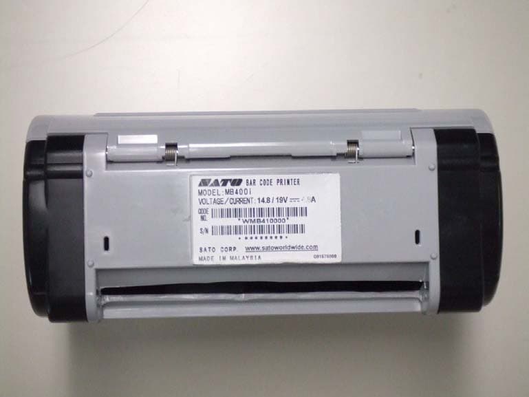
MMFMB400I-B1
Jul 08, 2007Barcode Printer
Equipment Class
DSS - Part 15 Spread Spectrum Transmitter