MNJ-MO072RTabletop Digital Color Video Monitor - Video Receiver
Dorel Juvenile Group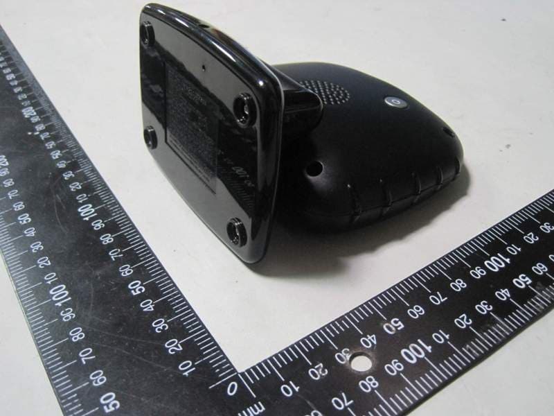
Click to zoom
Application Details
- Equipment Class
- DSS - Part 15 Spread Spectrum Transmitter
- Date of Grant
- May 31, 2012
- Application Purpose
- Original Equipment
- Date of Application
- May 31, 2012
- Equipment Note
- Tabletop Digital Color Video Monitor - Video Receiver
- Frequency Range
- 2409.00000000 - 2473.00000000
- Company
- Dorel Juvenile Group
- Country
- United States
Documents & Files
Document Text
Text extracted from the exhibit documents filed with the FCC. Open a document above to read the original.
Users Manual
User Guide 08180 (MO080) TrustView ™ Handheld Digital Color Video Monitor Birth & Up 4/10/12 4358-5930 Register for our eNewsletter and watch our experts on Safety 1 st TV safety1st.com Dorel Juvenile Group, Inc. warrants to the original purchaser that this TrustView™ Handheld Digital Color Video Monitor, is free from material and workmanship defects when used under normal conditions for a period of one (1) year from the date of purchase. Should the product contain defects in material or workmanship Dorel Juvenile Group, Inc., will repair or replace the product, at our option, free of charge. Purchaser will be responsible for all costs associated with packaging and shipping the product to Dorel Juvenile Group Consumer Relations Department at the address noted below and all other freight or insurance costs associated with the return. Dorel Juvenile Group will bear the cost of shipping the repaired or replaced product to the purchaser. Product should be returned in its original package accompanied by a proof of purchase, either a sales receipt or other proof that the product is within the warranty period. This warranty is void if the owner repairs or modifies the product or the product has been damaged as a result of misuse. This warranty excludes any liability other than that express stated previously, including but not limited to, and incidental or inconsequential damages. SOME STATES OR PROVINCES DO NOT ALLOW THE EXCLUSION OR LIMITATION OF INCIDENTAL OR CONSEQUENTIAL DAMAGES, SO THE ABOVE LIMITATION OR EXCLU- SION MAY NOT APPLY TO YOU. THIS WARRANTY GIVES YOU SPECIFIC LEGAL RIGHTS, AND YOU MAY ALSO HAVE OTHER RIGHTS THAT MAY VARY FROM STATE TO STATE OR PROVINCE TO PROVINCE. Thank you again for purchasing a Safety 1st product. We are not only about safety, we’re also about your satisfaction. If you have any questions or comments, please call our Consumer Relations department at 1-800-544-1108 or e-mail us at [email protected]. One (1) Year Limited Warranty 16 Please read the following instructions and warnings carefully. Keep these instructions for future reference. Tool needed: Flathead Screwdriver (not included) Thank you for purchasing a Safety 1st product. We are not only about safety, we're also about your satisfaction. If you have any questions or comments, please call our Consumer Relations department at 1-800-544-1108 or e-mail us at [email protected] Strangulation Hazard - Children have STRANGLED in cords. Keep cords out of reach of children more than 3 feet (0.9 m) away. WARNING! ©2012 Cosco Management, Inc. All Rights Reserved. Tous droits réservés. www.djgusa.com (800) 544-1108 www.safety1st.com Fabriqué en CHINE. Hecho en CHINA. Styles and colors may vary. Les styles et les couleurs peuvent varier. Distributed by (distribué par) Dorel Juvenile Group, Inc., 2525 State St., Columbus, IN 47201-7494 Dorel Distribution Canada, 873 Hodge, St. Laurent, QC H4N 2B1 For more help and resources, call 1-800-544-1108 or visit www.safety1st.com32 This monitor is not intended to be used as a medical monitor and its use should not replace proper adult supervision. You should check your child’s activity at regular intervals as this monitor will not alert parents to the silent activities of a child. CAUTION! For indoor use only. To reduce the risk of fire or electrical shock, do not expose this product to water or moisture. NEVER attempt to disassemble the product. This is dangerous and will void the warranty. WARNING! Important! • Please read all warnings and assembly instructions carefully before using the video monitor. Parent Unit is a Receiver. Baby Unit is a Transmitter. • Do not place units in crib or mount on crib. Keep out of reach of children. • Check your child’s activity at regular intervals, as this monitor will not alert parents to the silent activities of a child. • To prevent entanglement with the adapter cord, NEVER PLACE THE CORD IN OR NEAR A CRIB OR PLAYPEN. DO NOT place the Receiver anywhere its AC adapter cord is near children. • ALWAYS KEEP TRANSMITTER, RECEIVER AND AC ADAPTERS OUT OF REACH OF CHILDREN • This product is not a medical monitor and its use should not replace adult supervision. • Check the reception regularly. • NEVER use the Transmitter or Receiver near water. For example, do not use near a bath tub, bathroom sink, laundry tub, kitchen sink, in a wet basement, etc. • Always unplug the AC adapters from wall outlets during long periods of non-use. • Check to make sure outlet plates are not unusually hot to the touch. If they are, immediately unplug cords from these outlets. Check that all outlet connections are in good condition so that adapter is not loose or that no wiring is exposed. Have a qualified, licensed electrician check the wiring as soon as possible. • Position the Transmitter, Receiver and AC adapters to allow adequate ventilation and prevent these components from overheating. • To prevent overheating, keep the Transmitter, Receiver and AC adapters away from heat sources such as radiators, heat registers, stoves or other appliances (including amplifiers) that produce heat. Also keep these components out of direct sunlight. • Certain electronic devices are sensitive to magnetic fields and may be damaged permanently or temporarily disabled if exposed to a magnetic field that is too strong. Video screen will become distorted and/or discolored if exposed to a strong magnetic field. • Use only the AC adapters provided. Use of any other adapters may damage the Transmitter and/or Receiver. Plug AC adapters into standard household current only! (120V AC) To prevent entanglement and overheating, DO NOT use extension cords. • The AC adapters may become slightly warm to the touch during operation. This is normal. • Position the AC adapter cords so that they are not walked on or pinched by items placed upon or against them, paying particular attention to cords at AC adapter plugs, wall plugs and the point where the cords attach to the Transmitter a…
Text truncated - open the document above for the full version.
Attestation Statements
Designated frequency hopping algorithm: Pseudorandom Frequency Hopping Sequence Our system is use frequency hopping system. There are total 17 non-overlap channels in our hopping table shown below. Channel Index Frequency (MHz) Channel 1 2409 Channel 2 2413 Channel 3 2417 Channel 4 2421 Channel 5 2425 Channel 6 2429 Channel 7 2433 Channel 8 2437 Channel 9 2441 Channel 10 2445 Channel 11 2449 Channel 12 2453 Channel 13 2457 Channel 14 2461 Channel 15 2465 Channel 16 2469 Channel 17 2473 According to the communication environment, our system will take a random strategy let 17 channels into 17 difference hopping index be established a hopping index table as shown below. Hopping Index Channel Index HI 1 Channel 9 HI 2 Channel 13 HI 3 Channel 5 HI 4 Channel 16 HI 5 Channel 1 HI 6 Channel 10 HI 7 Channel 8 HI 8 Channel 6 HI 9 Channel 17 HI10 Channel 14 HI11 Channel 2 HI12 Channel 11 HI13 Channel 4 HI14 Channel 7 HI15 Channel 15 HI 16 Channel 3 HI 17 Channel 12 After a hopping index be used 256 times, our system will take a random strategy to establish a new hopping index table maybe as shown below. Hopping Index Channel Index HI 1 Channel 14 HI 2 Channel 7 HI 3 Channel 11 HI 4 Channel 4 HI 5 Channel 15 HI 6 Channel 17 HI 7 Channel 1 HI 8 Channel 8 HI 9 Channel 10 HI10 Channel 5 HI11 Channel 12 HI12 Channel 16 HI13 Channel 9 HI14 Channel 3 HI15 Channel 2 HI 16 Channel 13 HI 17 Channel 6 Now we give an example that how to generate our hopping sequence. After the hopping index table is established, our system will generate a random value for the hopping interval. If the successive two random values are 4 and 6, we will get the hopping sequence shown below. The red region uses the random value 4 and the blue one uses the random value 6. HI 1 -> HI 5 -> HI 11 -> HI 15 -> HI 4 -> HI 8 -> HI 14 -> HI 1 -> HI 7 -> HI 11 -> HI 17 -> HI 4 -> HI 10 -> HI 14 -> HI 3 -> HI 7 -> HI 13 -> HI 17 -> HI 6 -> HI 10 -> HI 16 -> HI 3 -> HI 9 -> HI 13 -> HI 2 -> HI 6 -> HI 12 -> HI 16 -> HI 5 -> HI 9 -> HI 15 -> HI 2 -> HI 8 -> HI 12 -> HI 1 Equal Hopping Frequency Use To guarantee the equal hopping frequency use, each frequency channel has the using times record in our system. The using times record will be added one when one frequency channel is used. Therefore we will compare the using times record before we decide the next frequency channel in the hopping sequence. When the using times record is larger than what we expect, we will bypass this frequency channel and than check next one until each frequency channel has the same times record value that we expect. This mechanism guarantees the equal hopping frequency use. System Receiver Input Bandwidth L.O. frequency of receiver: 4,000 K Hz System Receiver Hopping Capability A two-way low speed data channel makes it possible to exchange information. The transmitter will generate the adaptive hopping sequence and transmit hopping information to the receiver. The receiver will shift frequency following this hopping information. Therefore out system has the ability to keep frequency channel switch in synchronization. Section 15.247(h) The hopping sequence is generated by the transmitter. Therefore the different transmitters will generate the different hopping sequences. Besides, our device has a unique user ID for link registration and the transmitted hopping information is encrypted. If user ID is not match, no other FHSS system can join the link with our devices. If no decryption ability, other FHSS system will not follow our hopping sequence to shift frequency. Data frame structure: Timing structure PA On Baby Side RF Converge 260 us Long Slot Tx 2620 us RF Converge 270 us Rx 440 us One Frame 3590 us PA On 1 to 1 Parents Side RF Converge 260 us Rx 2620 us RF Converge 270 us One Frame 3590 us Guard Time 170 us Short Slot Tx 270 us
Cover Letter(s)
Page No. : 2 Dorel Juvenile Group 2525 State Street, Columbus, Indiana 47201-7494, USA Tel: 508-216-1850 Fax: 508-216-1812 Confidential Letter Date: 2011/10/27 Federal Communications Commission Authorization and Evaluation Division FCC ID:MNJ-MO072R Confidentiality Request Pursuant to Sections 0.457 and 0.459 of the Commission’s Rules, the Applicant Hereby requests confidential treatment of information accomparting this Application As outlined below: 1. Block Diagram 2. Circuit Diagram 3. Operational Description The above materials contain trade secrets and proprietary information not customarily released to the public. The public disclosure of these matters might be harmful to the Applicant and provide unjustified benefits to its competitors. The Applicant understands that pursuant to Rule 0.457, disclosure of this Application and all accompanying documentation will not be made before the date of the Grant for this application Sincerely, Applicant’s company name : Dorel Juvenile Group Applicant’s company address : 2525 State Street, Columbus, Indiana 47201-7494, USA Signature : Job Title and Dept. : Tony Fernandes / Quality Assurance Manager E-Mail : [email protected] Tel. : 508-216-1850
Cover Letter(s)
Page No. : 1 Dorel Juvenile Group 2525 State Street, Columbus, Indiana 47201-7494, USA Tel: 508-216-1850 Fax: 508-216-1812 Power of Attorney Date: 2011/10/27 Dear Sir, I hereby have entrusted the following person to be a proxy regarding application for Type Certification. Sporton International Inc. Address : No.8, Lane 724, Bo-ai St., Jhubei City, HsinChu County 302, Taiwan, R.O.C. Name : Leo Huang Job Title : Manager e-mail : [email protected] I am therefore responsible for the contents of the application. Brand name and model type of the specified radio equipment: Safety 1 st / MO072R / MO080VR FCC ID: MNJ-MO072R Product name: Tabletop Digital Color Video Monitor - Video Receiver FCC Grantee contact person information. Applicant’s company name : Dorel Juvenile Group Applicant’s company address : 2525 State Street, Columbus, Indiana 47201-7494, USA Signature : _____________________________ Job Title and Dept. : Tony Fernandes/ Quality Assurance Manager E-Mail : [email protected] Tel. : 508-216-1850
External Photos
Report No.: 190843 SPORTON International Inc. PAGE NUMBER : 1 OF 3 TEL : 886-2-2696-2468 ISSUED DATE : May 28, 2012 FAX : 886-2-2696-2255 Photographs of EUT Report No.: 190843 SPORTON International Inc. PAGE NUMBER : 2 OF 3 TEL : 886-2-2696-2468 ISSUED DATE : May 28, 2012 FAX : 886-2-2696-2255 Report No.: 190843 SPORTON International Inc. PAGE NUMBER : 3 OF 3 TEL : 886-2-2696-2468 ISSUED DATE : May 28, 2012 FAX : 886-2-2696-2255
Internal Photos
Report No.: 190843 SPORTON International Inc. PAGE NUMBER : 1 OF 12 TEL : 886-2-2696-2468 ISSUED DATE : May 28, 2012 FAX : 886-2-2696-2255 Photographs of EUT Report No.: 190843 SPORTON International Inc. PAGE NUMBER : 2 OF 12 TEL : 886-2-2696-2468 ISSUED DATE : May 28, 2012 FAX : 886-2-2696-2255 Report No.: 190843 SPORTON International Inc. PAGE NUMBER : 3 OF 12 TEL : 886-2-2696-2468 ISSUED DATE : May 28, 2012 FAX : 886-2-2696-2255 Report No.: 190843 SPORTON International Inc. PAGE NUMBER : 4 OF 12 TEL : 886-2-2696-2468 ISSUED DATE : May 28, 2012 FAX : 886-2-2696-2255 Report No.: 190843 SPORTON International Inc. PAGE NUMBER : 5 OF 12 TEL : 886-2-2696-2468 ISSUED DATE : May 28, 2012 FAX : 886-2-2696-2255 Report No.: 190843 SPORTON International Inc. PAGE NUMBER : 6 OF 12 TEL : 886-2-2696-2468 ISSUED DATE : May 28, 2012 FAX : 886-2-2696-2255 Report No.: 190843 SPORTON International Inc. PAGE NUMBER : 7 OF 12 TEL : 886-2-2696-2468 ISSUED DATE : May 28, 2012 FAX : 886-2-2696-2255 Report No.: 190843 SPORTON International Inc. PAGE NUMBER : 8 OF 12 TEL : 886-2-2696-2468 ISSUED DATE : May 28, 2012 FAX : 886-2-2696-2255 Report No.: 190843 SPORTON International Inc. PAGE NUMBER : 9 OF 12 TEL : 886-2-2696-2468 ISSUED DATE : May 28, 2012 FAX : 886-2-2696-2255 Report No.: 190843 SPORTON International Inc. PAGE NUMBER : 10 OF 12 TEL : 886-2-2696-2468 ISSUED DATE : May 28, 2012 FAX : 886-2-2696-2255 Report No.: 190843 SPORTON International Inc. PAGE NUMBER : 11 OF 12 TEL : 886-2-2696-2468 ISSUED DATE : May 28, 2012 FAX : 886-2-2696-2255 Report No.: 190843 SPORTON International Inc. PAGE NUMBER : 12 OF 12 TEL : 886-2-2696-2468 ISSUED DATE : May 28, 2012 FAX : 886-2-2696-2255
RF Exposure Info
Report No.: FR190843 FCC ID: MNJ-MO072R Page No. : B1 of B2 Appendix B. RF Exposure Report Report No.: FR190843 FCC ID: MNJ-MO072R Page No. : B2 of B2 1. RF Exposure Report 1.1. Applicable Standard In accordance with 47 CFR FCC Part 2 Subpart J, section 2.1093 this device has been defined as a portable device which is defined as a transmitting device designed to be used so that the radiating structure(s) of the device is/are within 20 centimeters of the body of the user. Portable devices must be evaluated using the specific FCC test procedures, and the SAR measurement techniques of OET Bulletin 65 Supplement C 01-01 and IEEE Std 1528-2003. When routine evaluation is required for SAR and the output power is ≤ 60/f(GHz) mW, the test reduction and test exclusion procedures given herein, or in KDB 616217 and its supplement or KDB 648474, are applicable. 1.2. SAR evaluation Max Peak Conducted Power for Hopping: 19.63 dBm Antenna Gain (dBi) Peak Output Power (dBm) Correction Factor (dB) Time Average Power (dBm) EIRP Power (dBm) Test Result 0.7 19.63 -11.67 7.96 8.66 Complies Note 1: Time Average Power = Peak Conducted Power + Antenna Gain + Correction Factor Note 2: E.I.R.P. power (8.66dBm) = Average power (7.96dBm) + Antenna gain (0.7dBi) ≦ SAR exempt threshold (60/f mW), therefore SAR evaluation is not required.
Test Report
SPORTON International Inc. No. 52, Hwa Ya 1st Rd., Kwei-Shan Hsiang, TaoYuan Hsien, Taiwan, R.O.C. Ph: 886-3-327-3456 / FAX: 886-3-327-0973 / www.sporton.com.tw Report Format Version: 01 FCC RADIO TEST REPORT Applicant’s company Dorel Juvenile Group Applicant Address 2525 State Street, Columbus, Indiana 47201-7494, USA FCC ID MNJ-MO072R Manufacturer’s company Dorel Juvenile Group Manufacturer Address 2525 State Street, Columbus, Indiana 47201-7494, USA Product Name Tabletop Digital Color Video Monitor - Video Receiver Brand Name Safety 1 st Model Name MO072R / MO080VR Test Rule 47 CFR FCC Part 15 Subpart C § 15.247 Test Freq. Range 2409 ~ 2473MHz Received Date Sep. 08, 2011 Final Test Date May 24, 2012 Submission Type Original Equipment Multiple Listing Please refer to section 3.7 Statement The test result in this report refers exclusively to the presented test model / sample. Without written approval of SPORTON International Inc., the test report shall not be reproduced except in full. The measurements and test results shown in this test report were made in accordance with the procedures and found in compliance with the limit given in ANSI C63.10-2009, 47 CFR FCC Part 15 Subpart C and FCC Public Notice DA00705. The test equipment used to perform the test is calibrated and traceable to NML/ROC. ILAC MRA Report No.: FR190843 Report Format Version: 01 Page No. : i of ii FCC ID: MNJ-MO072R Issued Date : May 29, 2012 Table of Contents 1. CERTIFICATE OF COMPLIANCE ......................................................................................................................... 1 2. SUMMARY OF THE TEST RESULT .......................................................................................................................... 2 3. GENERAL INFORMATION .................................................................................................................................. 3 3.1. Product Details....................................................................................................................................................................................3 3.2. Accessories .........................................................................................................................................................................................3 3.3. Table for Filed Antenna.......................................................................................................................................................................3 3.4. Table for Carrier Frequencies .............................................................................................................................................................4 3.5. Table for Test Modes ...........................................................................................................................................................................4 3.6. Table for Testing Locations..................................................................................................................................................................4 3.7. Table for Multiple Listing......................................................................................................................................................................5 3.8. Table for Supporting Units ...................................................................................................................................................................5 3.9. Table for Parameters of Test Software Setting .....................................................................................................................................5 3.10. Test Configurations .............................................................................................................................................................................6 4. TEST RESULT ..................................................................................................................................................... 9 4.1. AC Power Line Conducted Emissions Measurement...........................................................................................................................9 4.2. Maximum Peak Output Power Measurement ...................................................................................................................................13 4.3. Average Output Power Measurement ..............................................................................................................................................15 4.4. Hopping Channel Separation Measurement ...................................................................................................................................17 4.5. Number of Hopping Frequency Measurement.................................................................................................................................23 4.6. Dwell Time Measurement..................................................................................................................................................................25 4.7. Radiated Emissions Measurement ....................................................................................................................................................30 4.8. Band Edge Emissions Measurement .................................................................................................................................................39 4.9. Antenna Requirements .....................................................................................................................................................................42 5. LIST OF MEASURING EQUIPMENTS ................................................................................................................... 43 6. TEST LOCATION.............................................................................................................................…
Text truncated - open the document above for the full version.
Test Setup Photos
Report No.: FR190843 FCC ID: MNJ-MO072R Page No. : 1 of 5 Appendix A. Test Photos Report No.: FR190843 FCC ID: MNJ-MO072R Page No. : 2 of 5 1. Photographs of Conducted Emissions Test Configuration FRONT VIEW REAR VIEW Report No.: FR190843 FCC ID: MNJ-MO072R Page No. : 3 of 5 2. Photographs of Radiated Emissions Test Configuration Test Configuration: 9kHz ~30MHz FRONT VIEW REAR VIEW Report No.: FR190843 FCC ID: MNJ-MO072R Page No. : 4 of 5 Test Configuration: 30MHz~1GHz FRONT VIEW REAR VIEW Report No.: FR190843 FCC ID: MNJ-MO072R Page No. : 5 of 5 Test Configuration: Above 1GHz FRONT VIEW REAR VIEW
Contact Information
Applicant
Dan Desimone(Director R & A, Project Management)
Test Firm
Sporton International Inc.Alex Chen
Technical Specifications
| # | Rule Parts | Frequency Range | Power Output |
|---|---|---|---|
| 1 | 15C | 2.41 GHz - 2.47 GHz | 91.80 mW |
Other Applications from Dorel Juvenile Group
MNJ-MO191
Apr 09, 2024CryAssist Audio Monitor
Equipment Class
DSS - Part 15 Spread Spectrum Transmitter
MNJ-MO183TX
Dec 05, 2023See Pro 360 Baby Monitor
Equipment Class
NII - Unlicensed National Information Infrastructure TX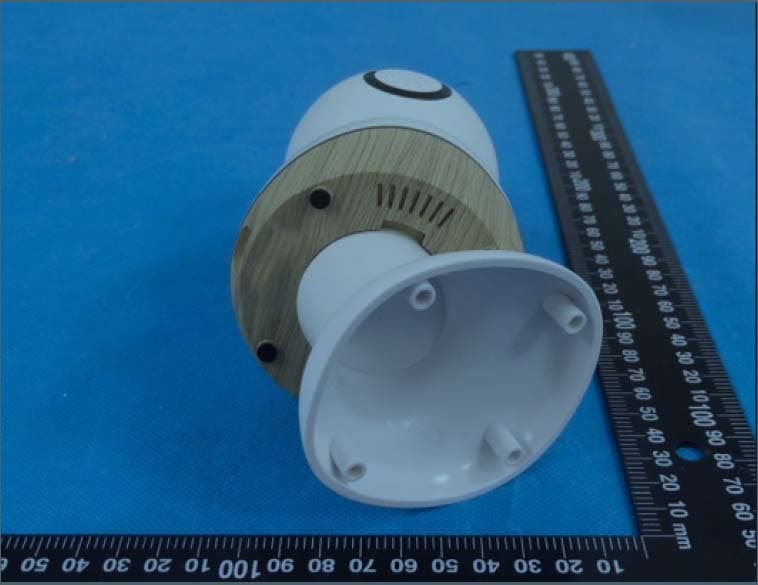
MNJ-MO180TX
Mar 29, 2023Smart Baby Monitor
Equipment Class
DTS - Digital Transmission System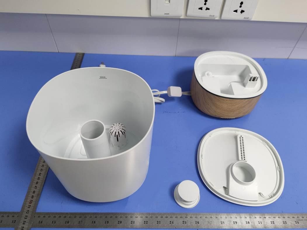
MNJ-IH555
Aug 11, 2021Humidifier
Equipment Class
DTS - Digital Transmission System
MNJ-MO173TX
Jun 06, 2021Baby Monitor
Equipment Class
DTS - Digital Transmission System