MNJ08020T900MHz Transmitter
Dorel Juvenile Group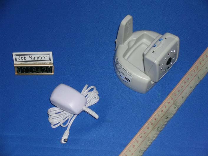
Click to zoom
Application Details
- Equipment Class
- DXX - Part 15 Low Power Communication Device Transmitter
- Date of Grant
- Sep 18, 2007
- Application Purpose
- Original Equipment
- Date of Application
- Sep 18, 2007
- Equipment Note
- 900MHz Transmitter
- Frequency Range
- 902.50000000 - 927.50000000
- Company
- Dorel Juvenile Group
- Country
- United States
Documents & Files
Document Text
Text extracted from the exhibit documents filed with the FCC. Open a document above to read the original.
Users Manual
4 • Existen riesgos de posibles lesiones provocadas por enredos. Mantenga el producto fuera del alcance del bebé. Retire de la cuna la cámara y el accesorio de cuna cuando el bebé comience a erguirse usando las manos y las rodillas. • No agregue lazos o correas adicionales al instalar en la cuna. Se requiere el armado por parte de un adulto. ADVERTENCIA 2Attach camera to crib mount: Connect the AC adapter to the bottomof the Baby’s Unit (Figure 2). Remove slack from cord and gently push down Baby’s Unit until it “snaps” onto crib mount (Figure 2a). 2 1d 3Attach to crib for close view: Remove nut from bracket (Figure 2). IMPORTANT NOTE ABOUT NUT: The nut is designed to fit flat, square or round style crib slats. Before tightening the nut, refer to Figure 3 diagram to determine how to position the nut against the crib slats. Determine where best to mount the Baby’s Unit. Place your arm inside the crib and slide bracket between crib slats (Figure 3a). The bracket should be about 1” (2.5 cm) below the top crib rail (Figure 3b) . Tighten the nut so that the plates are flat against the crib slats (Figure 3b). • Possible entanglement injury. Keep out of baby’s reach. Remove camera assembly and crib attachment from crib when baby begins to push up on hands and knees. • Donot add additional strings or straps to attach to crib. Adult assembly required. WARNING 3a Installing Your Close View Monitoring SystemCómo instalar el Sistema de Monitor Close View 2a 3b 3 Nut 1” 2Sujete la cámara al montaje en la cuna: Conecte el adaptador de CA a la parte inferior de la unidad del bebé (Figura 2). Tense la correa del cable y presione suavemente la unidad del bebé hasta que se encaje en el montaje de la cuna (Figura 2a). 3Instale en la cuna para una vista cercana: Retire la tuerca del soporte(Figura 3). NOTA IMPORTANTE SOBRE LA TUERCA: El diseño de la tuerca se adapta a listones de cuna planos, cuadrados o redondos. Antes de ajustar la tuerca, consulte el diagrama de la Figura 3para determinar cómo colocar la tuerca contra los listones de la cuna. Determine cuál es la mejor ubicación para montar la unidad del bebé. Coloque un brazo dentro de la cuna y deslice el soporte entre los listones de la cuna (Figura 3a). El soporte debe estar colocado 1 pulg. (2.5 cm) por debajo de la baranda superior de la cuna (Figura 3b). Ajuste la tuerca de modo que los apoyos queden planos contra los listones de la cuna (Figura 3b) . Plano Flat Redondo Round Cuadrado Square POSITION OF NUT FOR SHAPE OF CRIB SLATS: Tuerca 1Attach camera adapter to crib mount: Feed the cord through the camera adapter (Figure 1).Align the camera adapter to the crib mount and turn to secure (Figure 1a). 1 1Sujete el adaptador de la cámara al montaje en la cuna: Pase el cable por el adaptador de la cámara (Figura 1). Alinee el adaptador de la cámara con el montaje de la cuna y gírelo para asegurarlo (Figura 1a). 1a 5 3Attach to crib for close view (continued): Slide top tube into bottom tube (Figure 3c). Adjust camera to desired height by sliding it up or down, then secure in place using the screw (Figure 3d). DO NOT OVER TIGHTEN. Feed AC adapter end through wings and connect to other end of cord (Figure 3e). Thread wings onto lower rod. Open wing straps. Adjust the bottom nut until the wings align with the lower crib rail, by screwing the nut onto the threaded section of the lower rod, (both wings should touch the lower crib rail) (Figure 3f). Visually confirm that the crib attach tube is parallel with the crib side. The angle between the tube and the crib side can be adjusted by spreading the wings further apart to move the tube bottom closer or move the wings closer together to push the tube bottom further away from the crib. Once properly adjusted, thread each strap through the buckle, tighten and secure (Figure 3f). Connect the AC adapter to a power outlet and place cord out of the way. Installing Your Close View Monitoring SystemCómo instalar el Sistema de Monitor Close View 3f 3d Baranda inferior de la cuna Lower crib rail 3c 3Instale en la cuna para una vista cercana (continuación): Deslice el tubo superior dentro del tubo inferior (Figura 3c). Ajuste la cámara a la altura deseada deslizándola hacia arriba o hacia abajo. Luego, asegúrela en su lugar utilizando el tornillo (Figura 3d). NO AJUSTE EXCESIVAMENTE. Pase el extremo del adaptador de CA por las aletas y conéctelo con el otro extremo del cable (Figura 3e). Enrosque las aletas en la baranda inferior. Abra las correas de las aletas. Ajuste la tuerca inferior atornillándola a la parte roscada de la varilla, hasta que las aletas se encuentren alineadas con la baranda inferior la cuna. Ambas aletas deben tocar la baranda inferior de la cuna (Figura 3f). Verifique visualmente que el tubo de montaje en la cuna se encuentre paralelo a los lados de esta. El ángulo entre el tubo y los lados de la cuna puede ajustarse separando más las aletas para acercar a la cuna el extremo inferior del tubo, o acercándolas para alejarlo. Una vez que el tubo se encuentre adecuadamente ajustado, pase cada correa por la hebilla, ajústelas y asegúrelas (Figura 3f). Conecte el adaptador de CA a un tomacorriente y ponga el cable fuera del camino. 3e NOTE:The Portable Audio Receiver may use either the AC adapter or batteries. When plugged in, the AC adapter will be the source of power. 5For AC Power Use:Connect an AC adapter into the side of the Portable Audio Receiver (Figure 4). Connect the AC adapter into a power outlet. CAUTION:DONOTuse an adapter that did not come with this product. For Battery Use:Unscrew the screw on the back of the Portable Audio Receiver. Pull off the battery door and insert 4 AAA batteries (match polarity shown in Figure 5). Secure door with the screw. • When using batteries, check battery indicator regularly. Amber LED indicates the batteries are low. DO NOTuse on Portable Audio Receiver when batteries are low. CAUTION Cómo instalar el receptor portátil de audio: NOTA: El receptor portátil …
Text truncated - open the document above for the full version.
Block Diagram
BLK-8020LFT-USA-00 SFT-8020-USA 900M VIDEO BABY MONITOR(AUDIO PART) 0 REV : DATE : TITLE : MODEL NO. : DRAWN BY : CHECKED BY : EAGLETRON TELECOMMUNICATIONS LTD. DRAWING NO. : APPROVED BY : REVISION RECORD A B C D DATE: 1 2 3 4 5 6 D C B A LTR ECO NO: APPROVED: QS.XIONG 25/07/2007 25/07/2007 DATE : DATE : REGULATOR C202,C204,U201 9V MCU W741C2601 5V PLL IC(AUDIO) U1(MCD2926) EN DATA CLK PLL IC(VIDEO) U101(SP5055) SDA SCL LPF Q103 Q102,DV101 POWER AMP Q101 BANDPASS FILTER F101(915MHz) 5V IR CIRCUIT Q401.Q402 IRD2-D11 VIDEO SENSOR CIRCUIT U301,U302 CH1 908.5MHz CH2 921.5MHz LPF R8-10,C23-25 VCO & MODULATION VD1 Q2 L1 F1:908.5MHz F2:921.5MHz F1:463.75MHz F2:451.25MHz FINA2 CP2 POWER AMP Q1 F2(915MHz) BANDPASS FILTER CH1:927.5MHz CH2:902.5MHz SHEK KAIPING MIC AMP U202 AUDIO OUT VIDEO OUT KAMWAH 25/07/2007 U100 U203 J1 DC JACK 1 2 3 POWER-SW 1 2 X201 4MHz 1 2 CHANNEL-SW 1 2 X1 4MHz 1 2 X101 4MHz 1 2 X301 13.5MHz
External Photos
INTERTEK TESTING SERVICES External Photos FCC ID: MNJ08020T external photos - 1 of 1 External Photo - Front External Photo - Rear
Internal Photos
INTERTEK TESTING SERVICES Internal photos FCC ID: MNJ08020T internal photos - 1 of 4 Internal Photo - 1 Internal Photo - 2 INTERTEK TESTING SERVICES Internal photos FCC ID: MNJ08020T internal photos - 2 of 4 Internal Photo - 3 Internal Photo - 4 INTERTEK TESTING SERVICES Internal photos FCC ID: MNJ08020T internal photos - 3 of 4 Internal Photo - 5 Internal Photo - 6 INTERTEK TESTING SERVICES Internal photos FCC ID: MNJ08020T internal photos - 4 of 4 Internal Photo - 7 Internal Photo - 8
Operational Description
1 CIRCUIT DESCRIPTION CAMERA TX UNIT z Switch SW201 is used to power on/off the unit and change the channel between CH1 & CH2 . z Regulator Circuit includes the U201, C202, C204, R228. They provide constant voltage to the circuit. z MCU (U203-W741C2601) control PLL IC, SP5055 & MCD2926 to get the accurate audio & video transmit frequency for channel 1 & 2. z VIDEO PATH 1) The video Local Oscillator and Modulator is a combination of circuit components of Q102,VD101 which are constructed to form a video modulator circuit. Local Frequency: F1: 908.5MHz F2: 921.5MHz 2) Video LPF. & PLL are formed by Q103 & U101. the X101 provide 4MHz reference frequency to PLL SP5055 3) Video RF Amp is achieved by using a transistor Q101. The RF signal is applied to the base of this transistor Q101 for amplification only. The signal will be sent to the antenna via TX Match Filter. 4) Video Tx Match Filter is a filtering and matching circuit, which includes the capacitors C136 and F101; 5) The Video Antenna is a Koch type and solder directly onto RF PCB Boards; 6) The Video sensor circuit is formed by U301, X301. It transfer the image to CCIR video signal, then provide to video modulator. U302 regulate the 9V voltage to 5V and provide to U301. 7) IR circuit include Q401-402, U100, R408 & IRD1-10. In night it transmit IR light; z AUDIO PATH 1) The Audio Local Oscillator and Modulator is a combination of circuit components of Q2, L1 &VD1 which are constructed to form a audio modulator circuit. Local Frequency: F1: 463.75MHz F2: 451.25MHz 2) Audio LPF. & PLL are formed by C23-25, R9-10 & U1. the X1 provide 4MHz reference frequency to PLL MCD2926; 3) Audio Amp is achieved by U202-A, B to provide amplified audio signal to the audio modulator circuit. The AGC is controlled by Q201-202 for automatic level control. 4) AUDIO RF Amp and Multiplier (double) is achieved by using a transistor Q1. The LO signal is applied to the base of this transistor of Q1 for amplification and multiplication. The amplified and multiplied signal will be sent to the antenna via TX Match Filter to select wanted RF signal. The transmitter RF Frequency is: F1: 927.5MHz F2: 902.5MHz 5) AUDIO Tx Match Filter is a filtering and matching circuit, which includes the capacitors C1,C4,C5 and filter of F2; 6) The Audio Antenna is a Helix type and solder directly onto RF PCB Boards;
Schematics
SCH-8020LFTS-USA-00 SFT-8020LF-USA QS.XIONG 900M VIDEO BABY MONITOR (TX-SENSOR) 0 16 15 16 15 14 13 12 11 10 9 8 7 6 5 4 3 2 1 DESCRIPTION DRW APP DATE APPROVED BY : DRAWING NO. : EAGLETRON TELECOMMUNICATIONS LTD. CHECKED BY : DRAWN BY : MODEL NO. : TITLE : 1 2 3 4 5 6 7 8 9 10 11 12 13 14 A B C D E F G H I J A B C D E F G H I J DATE : REV : REV KamWah vcc Shek Kaiping 29/6/2007 PAGE: 1 OF 1 8V IN-PUT C319 0.47U C318 0.1U R301 1M C308 0.1UF C309 1UF X301 13.5MHz C301 10P C302 10P 15 FAST 16 BPED 17 GAMMA 18 MIRR 11 XTAL1 12 FSI 13 OENB 14 G4X 10 XTAL2 19 G8X 20 DVDD 21 DGND 22 CVO 23 OVDD 9 BKLT 8 EIA 7 SGND 6 VCBRT 5 ABOFF 24 ATBLK 25 DEGND 26 DEVDD 4 N50 3 VRCHG 2 SVDD 1 AVDD 27 VREQ 28 AGND U301 0V5116 R302 75 R305 10k R308 22K R309 10K R310 10k R312 10R 1 3 2 U302 AZ1117_5V C320 10UF/16V C321 47UF/6.3V R321 22 1/4W R322 22 1/4W IRD11 IRD10 IRD9 IRD8 IRD7 VR401 50K LED1 GREEN LED R401 2K2 C401 220U/16V R405 1K Q402 2SA1362 R404 10K R402 100R R408 LED-RES Q401 3904 R403 6K8 IRD2 IRD3 IRD4 IRD5 IRD6 R311 10k(NC) R409 100 FA1 FA2 C1 10UF/6.3V C2 10UF/6.3V U100 78L08 VO VCC VCC 29/06/2007 SCH-8020LFTRF-USA-00 SFT-8020LF-USA KAMWAH 900MHz BABY VIDEO MONITOR (TX-RF MODULE) 0 REV : I H 9 10 G F E D C B A 8 6 3 2 1 11 12 13 14 A B C D E F H I J 10 8 7 6 4 3 2 1 11 13 7 14 DATE : 5 4 J 5 9 EAGLETRON TELECOMMUNICATIONS LTD. TITLE : MODEL NO. : DRAWING NO. : DRAWN BY : CHECKED BY : APPROVED BY : 12 G F1: 908.5 MHZ F2: 921.5MHZ PAGE: 1 OF 2 F1: = 463.75 X 2 = 927.5MHZ F2: = 451.25 X 2 = 902.5MHZ SHEK KAIPING QS.XIONG 1 CHP 2 CR1 3 CR2 4 SDA 5 SCL 6 I/OP7 7 I/OP6 10 PSE 11 OP 12 VCC 13 RFI1 14 RFI2 15 VSS 16 DRO 8 I/OP5 9 I/OP4 U101 SP5055 R113 330 R114 330 R110 15K R107 7K5 R106 10K R105 100R R101 27K R102 N.M R104 0R R103 68R R108 15K R109 22K ANT1 C102 1000P C104 0.1UF C106 1000P C103 2p C107 0.1U C112 0.047U C113 0.47U Q102 BFG540/X C105 2P C109 2.2PF C108 3P DV101 1SV229 R137 100nH C114 0.022U Q103 BC846 C115 1000P R111 4R7 C116 1UF C117 0.1U X101 4.0MHz C118 0.1U VR101 5K C134 4p Q101 2SC3356 R130 100R C130 1000P C131 0.01U C137 1P C145 N.M C111 N.M C135 1P C136 3P F101 915M W1 10nH C140 3pF R138 1K R126 4K7 L102 10UH + C138 47U C1 N.M F2 915M C4 1P C5 2P Q1 2SC5594 R1 10K R2 560R C7 103 C8 5P Q2 MAS520 R3 220 C13 3P C14 3P R4 24K R6 390R C15 68P C16 473 C17 102 C18 7P C19 8P R5 15K L1 2*0.5*2T5 C20 3P C21 4p VD1 1SV229 R7 560R C22 102 R8 10K C23 103 R9 7.5K R10 30K C24 0.47U C25 103 1 FIN1 2 VCC1 3 CP1 4 GND1 5 LD 6 CLK 7 DATA 8 EN 9 BO 11 OSCI 12 S/W 13 GND2 14 CP2 15 VCC2 16 FIN2 10 OSCO U1 MCD2926 X1 4M C28 200P C29 200P C30 30P VC1 20P R11 1K R12 1K R13 1K R35 220 C53 15P C3 1.5P C2 N.M + C6 47UF R37 N.M ANT2 L103 10UH C9 0.47U R14 18R C11 103 C110 0.5P R15 820R TP2 TP5 C10 220P R16 0R C55 1P R134 220R L4 na C12 1P Q3 2SC1623 R17 5K1 R18 10K C31 NA SDA SCL FIN GND GND VIDEO CLK DATA EN VCC AUDIO +5V 4M FIN CH-SW SCH-8020LFTRF-USA-00 29/06/2007 SFT-8020LF-USA KAMWAH 900M VIDEO MONITOR (TX-CPU) 0 G 12 APPROVED BY : CHECKED BY : DRAWN BY : DRAWING NO. : MODEL NO. : TITLE : EAGLETRON TELECOMMUNICATIONS LTD. 9 5 J 4 5 DATE : 14 7 13 11 1 2 3 4 6 7 8 10 J I H F E D C B A 14 13 12 11 1 2 3 6 8 A B C D E F G 10 9 H I REV : ON OFF PAGE: 2 OF 2 QS.XIONG SHEK KAIPING MIC1 DC201 9V/300MA SW201-A POWER SW C201 0.1U C202 470U Vss Vout Vin 3 1 2 U201 L7805 C203 0.1U R228 N.M 1 2 X201 4M C245 N.M C244 N.M 1 RE2 2 RE3 3 VSS 4 VPP 5 DATA 6 COM3 7 COM2 8 COM1 9 COM0 10 SEG0 11 SEG1 12 SEG2 13 SEG3 14 SEG4 15 SEG5 16 SEG6 17 SEG7 18 SEG8 19 SEG9 20 SEG10 21 SEG11 22 SEG12 23 SEG13 24 14 25 SEG15 26 SEG16 27 SEG17 28 SEG18 29 SEG19 30 SEG20 31 SEG21 32 SEG22 33 SEG23 34 SEG24 35 SEG25 36 26 37 SEG27 38 SEG28 39 SEG29 40 SEG30 41 SEG31 42 VDD3 43 VDD2 44 VDD1 45 DH2 46 DH1 47 MODE 48 XOUT2 49 XIN2 50 VDD 51 XOUT1 52 XIN1 53 RES 54 INT 55 MFP 56 RA0 57 RA1 58 RA2 59 RA3 60 PB0 61 PB1 62 PB2 63 PB3 64 RC0 65 RC1 66 RC2 67 RC3 68 RD0 69 RD1 70 RD2 71 RD3 72 RE0 73 RE1 U203 W741C2601 R256 47K C243 0.1 R257 10R C246 0.47 TP1 TP3 TP4 1 2 SW201-B C204 470U + - 2 3 1 U202-A MC358 + - 6 5 7 U202-B MC358 8 4 U202-C MC358 R232 4K7 R231 2K2 C232 0.022 R233 10K R235 100K R234 100K R236 10K R237 51K C235 0.01 R242 270K R243 2K7 C238 0.1 R239 100K R238 100K R240 100K R241 4K7 C242 4700P C241 1000P Q201 2SA812 R244 10K C239 0.1 R245 180K C240 47U R246 100K R247 10K Q202 2SC1623 C236 0.1 C234 0.47 C233 0.1 C237 0.1 C230 47U R211 10K C222 1500P R222 56K Q203 2SA812 L2 10UH CW VR1 50K //MIC 1000pF R19 10K +5V +5V 4M +5V +5V +5V AUDIO SDA SCL EN DA CLK +5V CH-SW VCC
Test Report
- The evaluation data of the report will be kept for 3 years from the date of issuance. - This report is for the exclusive use of Intertek's Client and is provided pursuant to the agreement between Intertek and its Client. Intertek's responsibility and liability are limited to the terms and conditions of the agreement. Intertek assumes no liability to any party, other than to the Client in accordance with the agreement, for any loss, expense or damage occasioned by the use of this report. Only the Client is authorized to permit copying or distribution of this report and then only in its entirety. Any use of the Intertek name or one of its marks for the sale or advertisement of the tested material, product or service must first be approved in writing by Intertek. The observations and test results in this report are relevant only to the sample tested. This report by itself does not imply that the material, product, or service is or has ever been under an Intertek certification program. Intertek Testing Services Hong Kong Ltd. 2/F., Garment Centre, 576 Castle Peak Road, Kowloon, Hong Kong. Tel: (852) 2173 8888 Fax: (852) 2785 5487 Website: www.hk.intertek-etlsemko.com Dorel Juvenile Group Application For Certification (FCC ID: MNJ08020T) 900MHz Transmitter 07184201 TL/ ac September 5, 2007 INTERTEK TESTING SERVICES FCC ID: MNJ08020T i LIST OF EXHIBITS INTRODUCTION EXHIBIT 1: General Description EXHIBIT 2: System Test Configuration EXHIBIT 3: Emission Results EXHIBIT 4: Equipment Photographs EXHIBIT 5: Product Labelling EXHIBIT 6: Technical Specifications EXHIBIT 7: Instruction Manual INTERTEK TESTING SERVICES FCC ID: MNJ08020T ii MEASUREMENT/TECHNICAL REPORT Dorel Juvenile Group - MODEL: 08020 08043 FCC ID: MNJ08020T September 5, 2007 This report concerns (check one:) Original Grant X Class II Change Equipment Type: DXX - Low Power Transmitter (example: computer, printer, modem, etc.) Deferred grant requested per 47 CFR 0.457(d)(1)(ii)? Yes No X If yes, defer until: date Company Name agrees to notify the Commission by: date of the intended date of announcement of the product so that the grant can be issued on that date. Transition Rules Request per 15.37? Yes No X If no, assumed Part 15, Subpart C for intentional radiator - the new 47 CFR [05-04-07 Edition] provision. Report prepared by: Leung Wai Leung, Tommy Intertek Testing Services Hong Kong Ltd. 2/F., Garment Center, 576, Castle Peak Road, Kowloon, Hong Kong. Phone: 852-2173-8538 Fax: 852-2741-1693 INTERTEK TESTING SERVICES FCC ID: MNJ08020T iii Table of Contents 1.0 General Description............................................................................................ 2 1.1 Product Description ............................................................................................... 2 1.2 Related Submittal(s) Grants................................................................................... 2 1.3 Test Methodology.................................................................................................. 3 1.4 Test Facility ........................................................................................................... 3 2.0 System Test Configuration ................................................................................. 5 2.1 Justification ........................................................................................................... 5 2.2 EUT Exercising Software....................................................................................... 5 2.3 Details of EUT and Description of Peripherals........................................................ 6 2.4 Measurement Uncertainty...................................................................................... 7 2.5 Equipment Modification ......................................................................................... 7 3.0 Emission Results ................................................................................................ 9 3.1 Field Strength Calculation.................................................................................... 10 3.2 Radiated Emission Configuration Photograph...................................................... 12 3.3 Radiated Emission Data ...................................................................................... 13 3.4 Radiated Emission on the Bandedge ................................................................... 16 3.5 Conducted Emission Configuration Photograph................................................... 17 3.6 Conducted Emission Data ................................................................................... 18 4.0 Equipment Photographs ................................................................................... 20 5.0 Product Labelling.............................................................................................. 22 6.0 Technical Specifications ................................................................................... 24 7.0 Instruction Manual ............................................................................................ 26 INTERTEK TESTING SERVICES FCC ID: MNJ08020T iv List of attached file Exhibit type File Description filename Test Report Test Report report.pdf Operation Description Technical Description descri.pdf Radiated Emission Test Setup Photo Conducted Emission config photos.pdf Test Report Conducted Emission Test Result conduct.pdf Test Report Bandedge Plot emission.pdf External Photo External Photo external photos.doc Internal Photo Internal Photo internal photos.doc Block Diagram Block Diagram block.pdf Schematics Circuit Diagram circuit.pdf ID Label/Location Label Artwork and Location label.pdf User Manual User Manual manual.pdf INTERTEK TESTING SERVICES FCC ID: MNJ08020T 1 EXHIBIT 1 GENERAL DESCRIPTION INTERTEK TESTING SERVICES FCC ID: MNJ08020T 2 1.0 General Description 1.1 Product Description The Equipment Under Test (EUT) is a transmitter (Baby Unit of Baby Monitor wit…
Text truncated - open the document above for the full version.
Test Report
Report No.: 07184201 Tx Mode Ctrl No.: N/A PAGE 1 Report No.:07184201 Scan Settings (1 Range) |--------- Frequencies -----------||----------- Receiver Settings ------------| Start Stop Step IF BW Detector M-Time Atten Preamp OpRge 150k 30M 5k 10k PK+AV 10ms AUTO LN OFF 60dB Final Measurement: x QP / + AV Meas Time: 1 s Subranges: 16 Acc Margin: 20dB Transducer No. Start Stop Name 2 1 9k 30M EW0700 12 9k 30M EW0090 0 10 20 30 40 50 60 70 80 90 dBuV 100 0.15 MHz 30 110 F15Q F15A Report No.: 07184201 Tx Mode Ctrl No.: N/A Report No.:07184201 Scan Settings (1 Range) |--------- Frequencies -----------||----------- Receiver Settings ------------| Start Stop Step IF BW Detector M-Time Atten Preamp OpRge 150k 30M 5k 10k PK+AV 10ms AUTO LN OFF 60dB Final Measurement Results: Frequency QP Level QP Limit Delta MHz dBuV dBuV dB 0.40000 44.5 57.8 -13.3 0.46500 38.2 56.6 -18.4 0.66000 43.5 56.0 -12.5 0.86000 44.4 56.0 -11.6 1.51500 44.7 56.0 -11.3 1.58000 45.4 56.0 -10.6 2.30500 42.2 56.0 -13.8 3.22500 37.8 56.0 -18.2 4.40500 31.9 56.0 -24.1 Frequency AV Level AV Limit Delta MHz dBuV dBuV dB 0.39500 34.9 47.9 -13.0 0.53000 27.0 46.0 -19.0 0.59500 33.6 46.0 -12.4 0.86000 33.2 46.0 -12.8 1.51500 33.1 46.0 -12.9 1.78000 36.4 46.0 -9.6 2.24000 32.4 46.0 -13.6 3.29000 26.5 46.0 -19.5 * limit exceeded
Test Setup Photos
INTERTEK TESTING SERVICES The Worst Case Configuration Photographs FCC ID: MNJ08020T config photos (radiated emission) - 1 of 1 Radiated Emission Front View Rear View INTERTEK TESTING SERVICES The Worst Case Configuration Photographs FCC ID: MNJ08020T config photos (conducted emission) - 1 of 2 Conducted Emission Front View Right Side View INTERTEK TESTING SERVICES The Worst Case Configuration Photographs FCC ID: MNJ08020T config photos (conducted emission) - 2 of 2 Conducted Emission Left Side View
Contact Information
Applicant
Dan Desimone(Director R & A, Project Management)
Technical Contact
Intertek Testing Services Hong Kong Ltd.Tommy Leung
[email protected]852-2173-8538
2/F., Garment Centre, · Kowloon · Hong Kong
Non-Technical Contact
Intertek Testing Services Hong Kong Ltd.Tommy Leung
[email protected]852-2173-8538
Test Firm
Intertek Testing Services Hong KongBilly Chow
Technical Specifications
| # | Rule Parts | Frequency Range | Power Output |
|---|---|---|---|
| 1 | 15C | 902.5 MHz - 927.5 MHz | - |
Other Applications from Dorel Juvenile Group
MNJ-MO191
Apr 09, 2024CryAssist Audio Monitor
Equipment Class
DSS - Part 15 Spread Spectrum Transmitter
MNJ-MO183TX
Dec 05, 2023See Pro 360 Baby Monitor
Equipment Class
NII - Unlicensed National Information Infrastructure TX
MNJ-MO180TX
Mar 29, 2023Smart Baby Monitor
Equipment Class
DTS - Digital Transmission System
MNJ-IH555
Aug 11, 2021Humidifier
Equipment Class
DTS - Digital Transmission System
MNJ-MO173TX
Jun 06, 2021Baby Monitor
Equipment Class
DTS - Digital Transmission System