MNJ08041RTransmitter Unit of Baby Monitor
Dorel Juvenile Group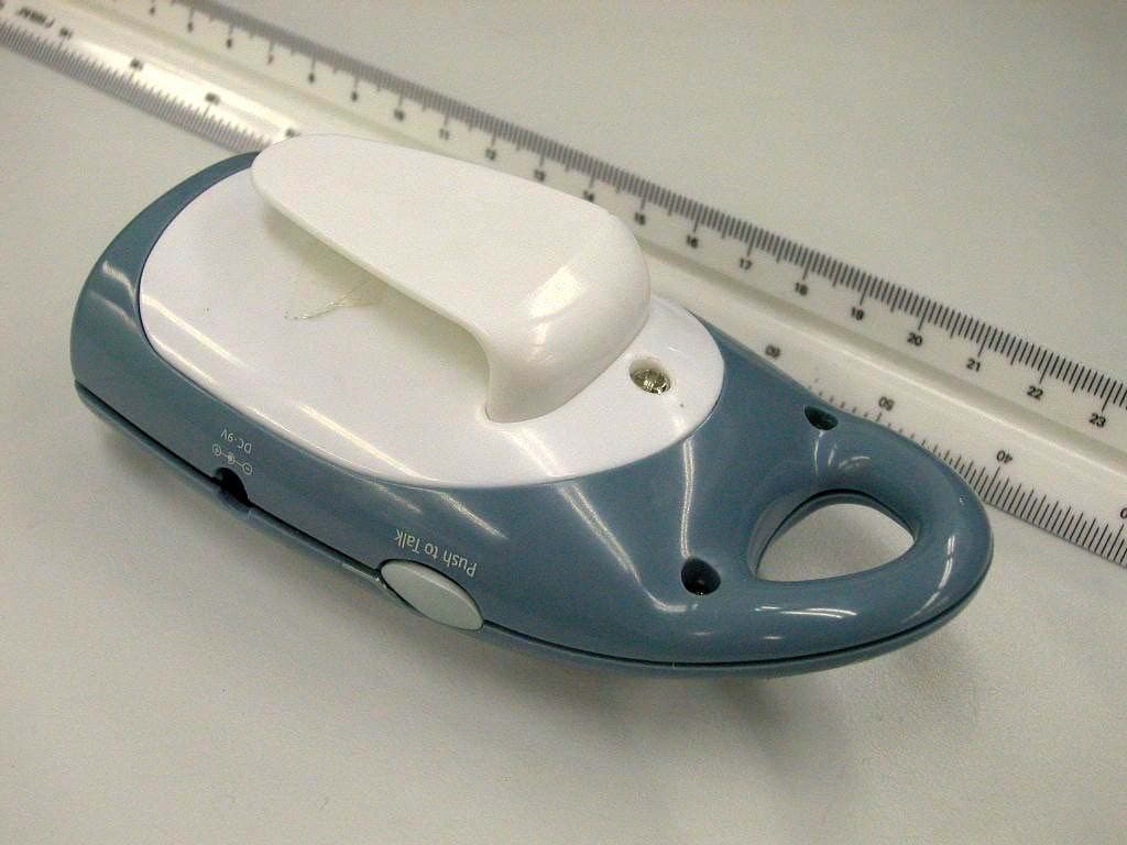
Click to zoom
Application Details
- Equipment Class
- DXT - Part 15 Low Power Transceiver, Rx Verified
- Date of Grant
- Nov 26, 2003
- Application Purpose
- Original Equipment
- Date of Application
- Nov 26, 2003
- Equipment Note
- Transmitter Unit of Baby Monitor
- Frequency Range
- 903.50000000 - 904.00000000
- Company
- Dorel Juvenile Group
- Country
- United States
Documents & Files
Document Text
Text extracted from the exhibit documents filed with the FCC. Open a document above to read the original.
Users Manual
3 4 User Guide Questions? Comments? Missing Parts? Contact Us: www.safety1st.com (800) 544-1108 ©2003 Dorel Juvenile Group Made in CHINA www.safety1st.com (800) 544-1108 Styles and colors may vary. Distributed by Dorel Juvenile Group, Inc., 2525 State Street, Columbus, IN 47201-7494 In Canada: 12345 Albert-Hudon, Suite 100, Montreal-N, QC Canada H1G 3K9 10/03 Quick Connection Two Way Monitor System 08041 08041 Quick Connection 10/9/03 11:25 AM Page 1 PLEASE READ THE FOLLOWING WARNINGS AND ALL ASSEMBLY INSTRUCTIONS CAREFULLY BEFORE USING THE QUICK CONNECTION TWO WAY MONITOR. KEEP THESE INSTRUCTIONS FOR FUTURE REFERENCE. TERMS USED IN WARNINGS:The term “Receiver” corresponds to “Parent Unit” and the term “Transmitter” corresponds to “Child Unit” in the rest of this instruction booklet. • The Quick Connection Two Way Monitor is not intended to replace responsible and proper parental supervision. • Check your child’s activity at regular intervals as this monitor will not alert parents to the silent activities of a child. • Before using your Quick Connection Two Way Monitor: - Read and follow all instructions carefully. - Read and observe all warnings on the product and in this instruction booklet. • To prevent entanglement with the adapter cord, NEVERplace the cord in or near a crib or playpen.DO NOTplace the Receiver anywhere its AC adapter cord are within reach of children. • ALWAYSKEEP THE TRANSMITTER, RECEIVER AND AC ADAPTERS OUT OF REACH OF CHILDREN. • This product is not intended to be used as a medical monitor and its use should not replace adult supervision. It is important that an adult stay within the viewing range of the Quick Connection Two Way Monitor at all times during use. • It is essential to check reception regularly. Please see the Testing Reception section for complete instructions. • The Receiver is intended for indoor use only. • NEVERuse the Transmitter or Receiver near water. For example, do not use near a bathtub, bathroom sink, laundry tub, kitchen sink, in a wet basement, etc. • Always unplug the AC adapters from wall outlets during long periods of non-use. • Position the Transmitter, Receiver and AC adapters to allow adequate ventilation and prevent these components from overheating. • To prevent overheating, keep the Transmitter, Receiver and AC adapters away from heat sources such as radiators, heat registers, stoves or other appliances (including amplifiers) which produce heat. Also keep these components out of direct sunlight. • Use only the AC adapters provided. Use of any other adapters may damage the Transmitter and/or Receiver. Plug the AC adapters into standard household current only (120V AC outlet)! To prevent entanglement and overheating, DO NOTuse extension cords. • The AC adapters may become slightly warm to the touch during operation. This is normal. • Position the AC adapter cords so that they are not walked on or pinched by items placed upon or against them, paying particular attention to cords at AC adapter plugs, wall plugs, and the point at which the cords attach to the Transmitter and Receiver. WARNING 2 08041 Quick Connection 10/9/03 11:25 AM Page 2 3 • This product should be serviced only by qualified service personnel at Dorel Juvenile Group when: -An AC adapter or its plug is damaged, -The Transmitter or Receiver have fallen, -Liquid has spilled into the Transmitter or Receiver or -The Transmitter or Receiver do not appear to operate normally or exhibit a marked change in performance • DO NOTattempt to service this product beyond that described in the Troubleshooting section at the end of these instructions. All other servicing should be referred to qualified personnel at Dorel Juvenile Group. NOTE:The LEDs emit IR (infra red) light that is not harmful. TO REDUCE THE RISK OF ELECTRICAL SHOCK, DO NOT REMOVE COVER OR BACK OF TRANSMITTER. NO SERVICEABLE PARTS INSIDE. REFER SERVICING TO DOREL JUVENILE GROUP CONSUMER RELATIONS (800) 544-1108. TO REDUCE THE RISK OF FIRE OR ELECTRICAL SHOCK, DO NOT EXPOSE THIS PRODUCT TO WATER OR MOISTURE. NEVER ATTEMPT TO OPEN THE CASE OF THE PRODUCT. THIS IS DANGEROUS AND WILL VOID THE WARRANTY. FCC Compliance Information NOTE:This equipment has been tested and found to comply with the limits for a Class B digital device, pursuant to Part 15 of the FCC Rules. These limits are designed to provide reasonable protection against harmful interference in a residential installation. This equipment generates, uses and can radiate radio frequency energy and, if not installed and used in accordance with the instructions, may cause harmful interference to radio communications. However, there is no guarantee that interference will not occur in a particular installation. If this equipment does cause harmful interference to radio or television reception, which can be determined by turning the equipment off and on, the user is encouraged to try to correct the interference by one or more of the following measures: • Re-orient or relocate the receiving antenna, • Increase the separation between the equipment and receiver, • Connect the equipment into an outlet on a circuit different from that to which the receiver is connected, • Consult the dealer or an experienced radio/TV technician for help. This device complies with Part 15 of the FCC Rules. Operation is subject to the following two conditions: (1) This device may not cause harmful interference, and (2) this device must accept any interference received, including interference that may cause undesired operation. WARNING:Changes or modifications to this unit not expressly approved by Dorel Juvenile Group could void the user’s authority to use the equipment. CAUTION WARNING 08041 Quick Connection 10/9/03 11:25 AM Page 3 4 Parent Unit Child Unit AC Adapter (2) 3 4 A B B C A Parts List • Lay out and identify all parts. • Do not return this product to the place of purchase. If any parts are missing, or if you are having difficulty using product visit our web site at www.safety1s…
Text truncated - open the document above for the full version.
Block Diagram
Winceiver WE904 WiNEDGE Electronics 0.1 - 1GHz Single Chip FM Transceiver © WiNEDGE Electronics (S) Pte Ltd Page 4 Rev Date: 150802 BLOCK DIAGRAM PIN CONFIGURATION DC Offset Correction (I) DC Offset Correction (Q) 90 LPF1 (I) 90 LPF2 (I) LPF1 (Q) LPF2 (Q) 10dB PAD IFIL1 IFIL2 IFIL3 Σ IF Filter BBSET IFSET P/D FM DEMOD Rx VCO PA Tx VCO REF OSC RSSI AFC AGC DCI DCQ RFI RFI QFIL1 QFIL2 QFIL3 RPLL RVCO RVCO RFO RFO CL K DATA LE TVCO TVCO OSCI OSCO DCRRSSI GCC AFCCAFC AUDIO/DATA TPLL VGA VGA VGA VGA DEMOD SYNTH BBSET QFIL2QFIL1QFIL3 PFGND VDDA VSSA VDDI 123456789101112 36 35 34333231302928272625 37 38 39 40 41 42 43 44 45 46 47 48 24 23 22 21 20 19 18 17 16 15 14 13 WE904 IFIL2 IFIL1 IFIL3 DCI DCQ DCR GCC VDDT2 TVCO TVCO VDDT1 TPLL SUBS VSSR RPLL VDDR1 RVCO RVCO VDDR2 IFSET ACGND AFC AFCC AUDO RFIRFI VSSI RSSI VSSTVSSORFORFOVDDOVDDOSCOOSCIVSSCLKDATALE TOP VIEW BBSET QFIL2QFIL1QFIL3 PFGND VDDA VSSA VDDI 123456789101112 36 35 34333231302928272625 37 38 39 40 41 42 43 44 45 46 47 48 24 23 22 21 20 19 18 17 16 15 14 13 WE904 IFIL2 IFIL1 IFIL3 DCI DCQ DCR GCC VDDT2 TVCO TVCO VDDT1 TPLL SUBS VSSR RPLL VDDR1 RVCO RVCO VDDR2 IFSET ACGND AFC AFCC AUDO RFIRFI VSSI RSSI VSSTVSSORFORFOVDDOVDDOSCOOSCIVSSCLKDATALE TOP VIEW
External Photos
Test Setup FCCID : MNJ08041R External Photo - front External Photo - rear
Internal Photos
Test Setup FCC ID : MNJ08041R Internal Photo - 1 Internal Photo – 2 Test Setup FCC ID : MNJ08041R Internal Photo - 3 Internal Photo – 4 Test Setup FCC ID : MNJ08041R Internal Photo - 5 Internal Photo - 6 Test Setup FCC ID : MNJ08041R Internal Photo - 7
Operational Description
1 DESCRIPTION FOR THE MODEL SFT-08041 Parent Unit Transmitter part z Tx Match Filter is a filtering and matching circuit, which includes the capacitors C74, C10, C12 and filter of F1. z RF Amp is achieved by using a transistor Q7. The RF signal is applied to the base of this transistor of Q7 from IC U1. The signal will be sent to the antenna via TX Match Filter F1. z The Local Oscillator is a combination of circuit components of U1 and L4, L11. The transistors Q1, Q4-6 and Q8 consist of the audio amplifiers that the picked up from the microphone. This audio signal is fed the IC U1 to modulate. z Phase Lock Loop are formed by the circuit built in the IC U1 and the external components R58, R82, C47, C82, C31 and C32. z CPU (W541E260) provides a system control on several parts, like PLL control, Tx/Rx switch, battery indication, and channel selection. z IC U6-B functions as the receiver signal detection. When the baby unit is received the RF signal from parent unit, the pin 7 of IC 6-B will feed a high to CPU that control the unit to entry receiver mode. Otherwise, the unit is in transmitter mode. z The button SW3 used to control the unit that goes to the transmitter mode when is pressed down. In the normal, the parent unit is in receiver mode.
Schematics
8041M00.sch-1 - Thu Sep 18 13:36:57 2003 8041M00.sch-2 - Thu Sep 18 13:37:51 2003
Test Report
• The test results reported in this test report shall refer only to the sample actually tested and shall not refer or be deemed to refer to bulk from which such a sample may be said to have been obtained. • This report shall not be reproduced except in full without prior authorization from Intertek Testing Services Hong Kong Limited. • For Terms And Conditions of the services, it can be provided upon request. • The evaluation data of the report will be kept for 3 years from the date of issuance. Intertek Testing Services Hong Kong Ltd. 2/F., Garment Centre, 576 Castle Peak Road, Kowloon, Hong Kong. Tel: (852) 2173 8888 Fax: (852) 2371 0521 Website: www.hk.intertek-etlsemko.com Dorel Juvenile Group Application For Certification (FCC ID: MNJ08041R) Transmitter 0316692 DL/ Sandy November 5, 2003 INTERTEK TESTING SERVICES FCC ID: MNJ08041R i LIST OF EXHIBITS INTRODUCTION EXHIBIT 1: General Description EXHIBIT 2: System Test Configuration EXHIBIT 3: Emission Results EXHIBIT 4: Equipment Photographs EXHIBIT 5: Product Labelling EXHIBIT 6: Technical Specifications EXHIBIT 7: Instruction Manual EXHIBIT 8: Miscellaneous Information INTERTEK TESTING SERVICES FCC ID: MNJ08041R ii MEASUREMENT/TECHNICAL REPORT Dorel Juvenile Group - MODEL: DJG* 08041 FCC ID: MNJ08041R November 5, 2003 This report concerns (check one:) Original Grant X Class II Change Equipment Type: Low Power Transmitter (example: computer, printer, modem, etc.) Deferred grant requested per 47 CFR 0.457(d)(1)(ii)? Yes No X If yes, defer until: date Company Name agrees to notify the Commission by: date of the intended date of announcement of the product so that the grant can be issued on that date. Transition Rules Request per 15.37? Yes No X If no, assumed Part 15, Subpart C for intentional radiator - the new 47 CFR [08-20-02 Edition] provision. Report prepared by: Derek Leung Intertek Testing Services 2/F., Garment Center, 576, Castle Peak Road, HONG KONG. Phone: 852-2173-8504 Fax: 852-2371-0521 INTERTEK TESTING SERVICES FCC ID: MNJ08041R iii Table of Contents 1.0 General Description............................................................................................ 2 1.1 Product Description ............................................................................................ 2 1.2 Related Submittal(s) Grants ............................................................................... 2 1.3 Test Methodology............................................................................................... 3 1.4 Test Facility........................................................................................................ 3 2.0 System Test Configuration ................................................................................. 5 2.1 Justification ........................................................................................................ 5 2.2 EUT Exercising Software.................................................................................... 5 2.3 Special Accessories ........................................................................................... 5 2.4 Equipment Modification ...................................................................................... 6 2.5 Measurement Uncertainty .................................................................................. 6 2.6 Support Equipment List and Description ............................................................. 6 3.0 Emission Results ................................................................................................ 8 3.1 Field Strength Calculation................................................................................... 9 3.2 Radiated Emission Configuration Photograph................................................... 11 3.3 Radiated Emission Data ................................................................................... 12 3.4 Conducted Emission Configuration Photograph................................................ 14 3.5 Conducted Emission Data .....................................................................................15 4.0 Equipment Photographs ................................................................................... 17 5.0 Product Labelling.............................................................................................. 19 6.0 Technical Specifications ................................................................................... 21 7.0 Instruction Manual ............................................................................................ 23 8.0 Miscellaneous Information ............................................................................... 25 8.1 Bandwidth Plot ................................................................................................. 26 8.2 Discussion of Pulse Desensitization.................................................................. 27 8.3 Emissions Test Procedures .............................................................................. 28 INTERTEK TESTING SERVICES FCC ID: MNJ08041R iv List of attached file Exhibit type File Description filename Test Report Test Report report.pdf Operation Description Technical Description descri.pdf Test Setup Photo Radiated Emission radiated photos.doc Test Setup Photo Conducted Emission conducted photos.doc Test Report Conducted Emission Test Result conducted.pdf Test Report Bandwidth Plot bw.pdf External Photo External Photo external photos.doc Internal Photo Internal Photo internal photos.doc Block Diagram Block Diagram block.pdf Schematics Circuit Diagram circuit.pdf ID Label/Location Label Artwork and Location label.pdf User Manual User Manual manual.pdf INTERTEK TESTING SERVICES FCC ID: MNJ08041R 1 EXHIBIT 1 GENERAL DESCRIPTION INTERTEK TESTING SERVICES FCC ID: MNJ08041R 2 1.0 General Description 1.1 Product Description The Equipment Under Test (EUT) is a Transmitter operating 903.5 and 904MHz. The EUT is powered by 4 x 1.5V “AAA” alkaline ba…
Text truncated - open the document above for the full version.
Test Report
Report No.:0316692 Ctrl No.:N/A PAGE 1 Tested By:Hong, Report No.:0316692 Scan Settings (1 Range) |--------- Frequencies -----------||----------- Receiver Settings ------------| Start Stop Step IF BW Detector M-Time Atten Preamp OpRge 150k 30M 5k 10k PK+AV 10ms AUTO LN OFF 60dB Final Measurement: x QP / + AV Meas Time: 1 s Subranges: 16 Acc Margin: 20dB Transducer No. Start Stop Name 22 9k 30M EW0699 0 10 20 30 40 50 60 70 80 90 dBuV 100 0.15 MHz 30110 F15Q F15A Report No.:0316692 Ctrl No.:N/A Tested By:Hong, Report No.:0316692 Scan Settings (1 Range) |--------- Frequencies -----------||----------- Receiver Settings ------------| Start Stop Step IF BW Detector M-Time Atten Preamp OpRge 150k 30M 5k 10k PK+AV 10ms AUTO LN OFF 60dB Final Measurement Results: no Results
Test Setup Photos
Test Setup FCCID : MNJ08041R Radiated - front Radiated - rear
Test Setup Photos
Test Setup FCCID : MNJ08041R Conduct Photo - 1 Conduct Photo - 2 Test Setup FCCID : MNJ08041R Conduct Photo - 3
Contact Information
Applicant
Dan Desimone(Director R & A, Project Management)
Technical Contact
Intertek Testing Services Hong Kong Ltd.Derek Leung
[email protected]852-2173-8504
2/F., Garment Centre, · Kowloon, · Hong Kong
Non-Technical Contact
Intertek Testing Services Hong KongDerek Leung
[email protected]852-2173-8504
Test Firm
Intertek Testing Services Hong KongBilly Chow
Technical Specifications
| # | Rule Parts | Frequency Range | Power Output |
|---|---|---|---|
| 1 | 15C | 903.5 MHz - 904 MHz | - |
Other Applications from Dorel Juvenile Group
MNJ-MO191
Apr 09, 2024CryAssist Audio Monitor
Equipment Class
DSS - Part 15 Spread Spectrum Transmitter
MNJ-MO183TX
Dec 05, 2023See Pro 360 Baby Monitor
Equipment Class
NII - Unlicensed National Information Infrastructure TX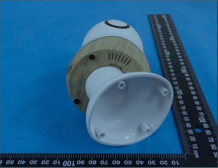
MNJ-MO180TX
Mar 29, 2023Smart Baby Monitor
Equipment Class
DTS - Digital Transmission System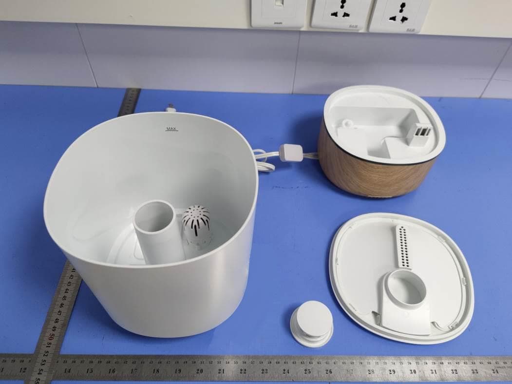
MNJ-IH555
Aug 11, 2021Humidifier
Equipment Class
DTS - Digital Transmission System
MNJ-MO173TX
Jun 06, 2021Baby Monitor
Equipment Class
DTS - Digital Transmission System