MNJ08044T49MHz BABY MONITOR
Dorel Juvenile Group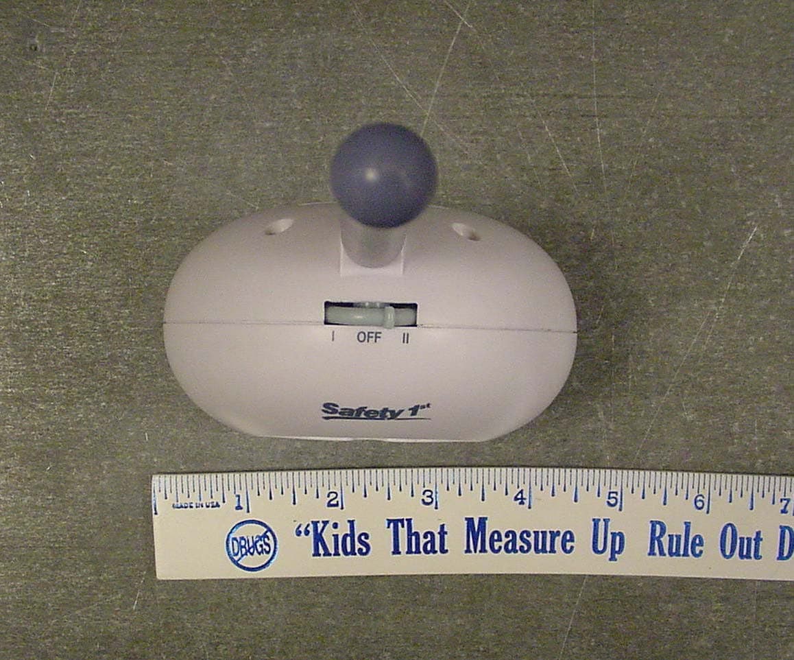
Click to zoom
Application Details
- Equipment Class
- DXX - Part 15 Low Power Communication Device Transmitter
- Date of Grant
- Dec 01, 2004
- Application Purpose
- Original Equipment
- Date of Application
- Dec 01, 2004
- Equipment Note
- 49MHz BABY MONITOR
- Frequency Range
- 49.85000000 - 49.87000000
- Company
- Dorel Juvenile Group
- Country
- United States
Documents & Files
Document Text
Text extracted from the exhibit documents filed with the FCC. Open a document above to read the original.
Users Manual
Models 08044, 08045 Sound View Monitor User Guide NOTE: 08045 comes with two receivers ©2004 Dorel Juvenile Group Made in CHINA www.safety1st.com (800) 544-1108 Styles and colors may vary. Distributed by Dorel Juvenile Group, Inc., 2525 State Street, Columbus, IN 47201-7494 In Canada: 12345 Albert-Hudon, Suite 100, Montreal-N, QC Canada H1G 3K9 11/04 4358-3549 ©2004 Dorel Juvenile Group Producto fabricado en CHINA www.safety1st.com (800) 544-1108 Los estilos y colores pueden variar. Distribuido por Dorel Juvenile Group, Inc. 2525 State Street Columbus, IN 47201-7494 En Canadá: 12345 Albert-Hudon, Suite 100, Montréal-N, QC Canadá H1G 3K9 11/04 4358-3549 ADVERTENCIA: POR FAVOR LEA DETENIDAMENTE LAS SIGUIENTES ADVERTENCIAS Y TODAS LAS INSTRUCCIONES DE MONTAJE ANTES DE UTILIZAR EL SISTEMA DE MONITOR HOME CONNECTION . GUARDE ESTAS INSTRUCCIONES PARA USO FUTURO. TÉRMINOS USADOS EN LAS ADVERTENCIAS: El término “Receptor” corresponde a la “Unidad de los padres” y el término “Transmisor” corresponde a la “Unidad del bebé” en el resto de este folleto de instrucciones. • Monitor bidir eccional Quick Connectionno está pensado para reemplazar la supervisión responsable y adecuada por parte de los padres. • Compruebe la actividad de su hijo/a a intervalos regulares, ya que este monitor no alertará a los padres de las actividades silenciosas de un niño. • Antes de utilizar Monitor bidireccional Quick Connection: - Lea y siga cuidadosamente todas las instrucciones. -Lea y observe todas las advertencias en el producto y en este folleto de instrucciones. • Para evitar enredarse con el cable del adaptador, NUNCA coloque el cable dentro ni cerca de una cuna o corral. NOcoloque el Receptor o Transmisor en ningún lugar donde el cable del adaptador de CA podría estar al alcance de los niños. • SIEMPREMANTENGA EL TRANSMISOR Y EL RECEPTOR Y LOS ADAPTADORES DE CA FUERA DEL ALCANCE DE LOS NIÑOS. • Este producto no está pensado para utilizarse como monitor médico y su uso no debe reemplazar la supervisión por parte de adultos. • Es esencial comprobar con regularidad la recepción. Por favor consulte la sección Cómo comprobar la recepción, para obtener instrucciones completas. • El transmisorestán indicados solamente para usarse en ambientes interiores. • NUNCAuse el transmisor o receptor cerca del agua. Por ejemplo, no los use cerca de una bañera, un lavabo, fregadero de la lavandería o de la cocina, en un sótano con humedad, etc. • Siempre desenchufe los adaptadores de CA de los tomacorrientes de la pared cuando no se van a usar durante periodos de tiempo prolongados. • Coloque el transmisor, el receptor y los adaptadores de CA de manera que tengan ventilación adecuada para evitar que estos componentes se recalienten. • Para evitar el sobrecalentamiento, mantenga el transmisor, el receptor y los adaptadores de CA alejados de fuentes de calor como radiadores, registros de calefacción, estufas y otros electrodomésticos (incluyendo amplificadores) que producen calor. Mantenga siempre estos componentes alejados de la luz directa del sol. • Use solamente los adaptadores de CA proporcionados. El uso de cualquier otro adaptador podría dañar el receptor y/o el receptor. Enchufe los adaptadores de CA solamente en un tomacorrientes estándar de la casa (120 V CA). Para evitar enredos y sobrecalentamiento, NOutilice cables de extensión. • Los adaptadores de CA podrían sentirse ligeramente calientes al tacto durante el funcionamiento. Esto es normal. • Coloque los cables de los adaptadores de CA de manera que no se camine sobre ellos, ni queden apresados por objetos que se Models08044, 08045 Sound View Monitor Guía del usuario NOTA: 08045 comes with two receivers WARNING: PLEASE READ THE FOLLOWING WARNINGS AND ALL ASSEMBLY INSTRUCTIONS CAREFULLY BEFORE USING THE SOUND VIEW MONITOR. KEEP THESE INSTRUCTIONS FOR FUTURE REFERENCE. TERMS USED IN WARNINGS: The term “Receiver” corresponds to “Parent’s Unit” and the term “Transmitter” corresponds to “Baby’s Unit” in the rest of this instruction booklet. • The Sound View Monitor is not intended to replace responsible and proper parental supervision. • Check your child’s activity at regular intervals as this monitor will not alert parents to the silent activities of a child. • Before using your Sound View Monitor: - Read and follow all instructions carefully. - Read and observe all warnings on the product and in this instruction booklet. • To prevent entanglement with the adapter cord, NEVERplace the cord in or near a crib or playpen. DO NOTplace the Receiver or Transmitter anywhere its AC adapter cord are within reach of children. • ALWAYSKEEP THE TRANSMITTER, RECEIVER AND AC ADAPTERS OUT OF REACH OF CHILDREN. • This product is not intended to be used as a medical monitor and its use should not replace adult supervision. • It is essential to check reception regularly. Please see the Testing Reception section for complete instructions. • The Transmitter is intended for indoor use only. • NEVERuse the Transmitter or Receiver near water. For example, do not use near a bathtub, bathroom sink, laundry tub, kitchen sink, in a wet basement, etc. • Always unplug the AC adapters from wall outlets during long periods of non-use. • Position the Transmitter, Receiver and AC adapters to allow adequate ventilation and prevent these components from overheating. • To prevent overheating, keep the Transmitter, Receiver and AC adapters away from heat sources such as radiators, heat registers, stoves or other appliances (including amplifiers) which produce heat. Also keep these components out of direct sunlight. • Use only the AC adapters provided. Use of any other adapters may damage the Transmitter and/or Receiver. Plug the AC adapters into standard household current only (120V AC outlet)! To prevent entanglement and overheating, DO NOTuse extension cords. • The AC adapters may become slightly warm to the touch during operation. This is normal. • Position the AC adapter cords so that they are not walked…
Text truncated - open the document above for the full version.
External Photos
MNJ08044T Exterior Photos Page 1 of 4 Rear View of EUT MNJ08044T Exterior Photos Page 2 of 4 Front View MNJ08044T Exterior Photos Page 3 of 4 Top View, showing On/Off /Channel Selector switch. MNJ08044T Exterior Photos Page 4 of 4 Side View.
Internal Photos
MNJ08044T Interior Photos Page 1 of 4 Interior with front cover removed showing solder side of PCB and microphone installation. MNJ08044T Interior Photos Page 2 of 4 Solder side of PCB MNJ08044T Interior Photos Page 3 of 4 Component side of PCB MNJ08044T Interior Photos Page 4 of 4 Antenna and its connection with cover removed.
Test Report
Compliance Worldwide, Inc. – 357 Main Street – Sandown, NH 03873 (603) 887 3903 Fax 887 6445 http://www.cw-inc.com TEST NUMBER - 350-04 TEST REPORT TO INDUSTRY CANADA RSS 210 SECTION 8.6.2 FEDERAL COMMUNICATIONS COMMISSION CFR47 PART15.235 Low Power License-Exempt Radio communication Devices Intentional Radiators for Dorel Juvenile Group Canton Commerce Center 45 Dan Road Canton, MA 02021 800-909-7133 of 49MHz Baby Monitor Model 08044 FCC ID: MNJ08044T on 10/11/04 Tested by _____________________________________ Andrew Mertinooke Reviewed by _____________________________________ Clifton P. Brick This report may not be duplicated, except in full without written permission from Compliance Worldwide, Inc. Page 2 of 30 Compliance Worldwide, Inc. – 357 Main Street – Sandown, NH 03873 (603) 887 3903 Fax 887 6445 http://www.cw-inc.com TEST NUMBER - 350-04 TABLE OF CONTENTS • Test Description • Test Results and Conclusions • Test Procedures • RSS 210 /Part 15 Subpart C Test Limits • Test Facility Description • Test Setup and Connection Information • Test Measurements and Results Radiated Measurements Radiated Output Power & Occupied Bandwidth Conducted Measurements • Notes and Comments • Photographs Radiated Test Setup (Front & Rear) Conducted Test Setup (Front & Rear) Exterior and Interior Photographs of Product Page 3 of 30 Compliance Worldwide, Inc. – 357 Main Street – Sandown, NH 03873 (603) 887 3903 Fax 887 6445 http://www.cw-inc.com TEST NUMBER - 350-04 TEST DESCRIPTION 1. TEST OBJECTIVE To test the 49MHz Baby Monitor 08044 to RSS 210 / Part 15 Subpart C Rules and write a report. 2. E.U.T. DESCRIPTION GENERAL The 49MHz Baby Monitor 08044 is a 49 MHz band 2 channel baby monitor. SERIAL NUMBERS: Production Prototype Page 4 of 30 Compliance Worldwide, Inc. – 357 Main Street – Sandown, NH 03873 (603) 887 3903 Fax 887 6445 http://www.cw-inc.com TEST NUMBER - 350-04 TEST RESULTS AND CONCLUSIONS PRODUCT TESTED - 49MHz Baby Monitor MODEL NUMBER - 08044 RADIATED TEST RESULTS The test results show that the emissions radiated from this equipment are in compliance with IC Rules RSS 210 / FCC Rules Part 15 Subpart C. OCCUPIED BANDWIDTH & OUTPUT POWER The test results show that the occupied bandwidth and output power of this equipment are in compliance with IC Rules RSS 210 / FCC Rules Part 15 Subpart C . CONDUCTED TEST RESULTS The test results show that the emissions conducted through the power line from this equipment are in compliance with IC Rules RSS 210 / FCC Rules Part 15 Subpart C. ANALYSIS AND CONCLUSIONS Based upon the radiated and conducted measurements we find that this equipment is within the limits of the IC Rules RSS 210 / FCC Rules Part 15 Subpart C. All results are based on a test of one sample, and represent other production units, only in as much as a sample represents other production units. If any significant changes are made to the unit, the changes shall be evaluated and a retest may be required. NOTES (Special conditions unique to this test) None. Page 5 of 30 Compliance Worldwide, Inc. – 357 Main Street – Sandown, NH 03873 (603) 887 3903 Fax 887 6445 http://www.cw-inc.com TEST NUMBER - 350-04 TEST PROCEDURES 1. TEST EQUIPMENT A. HP 8546A (9 kHz - 6.5 GHz) EMI Receiver w/ RF Filter Section, S/N 3704A00323 / 3650A00360. Calibration Date 1-16-2004, calibrated annually. B. Com-Power Biconilog Antenna, Model AC220, S/N 25509. Calibration Date 7-16-2004, calibrated annually. C. EMCO LISN, Model EM 3825/2, S/N 9109-1860. Calibration Date: 3-10-2004, calibrated annually. 2. FREQUENCY RANGE TO BE SCANNED. A. Radiated Test from 30 MHz to 40 GHz (or the 10 th harmonic of the highest frequency whichever is lower). B. Conducted Test from 150 kHz to 30 MHz. Page 6 of 30 Compliance Worldwide, Inc. – 357 Main Street – Sandown, NH 03873 (603) 887 3903 Fax 887 6445 http://www.cw-inc.com TEST NUMBER - 350-04 3. TEST PROCEDURES. Radiated test procedure: The EUT, associated cables and peripheral devices are placed on the supporting table and any support equipment is placed off the site. The EUT is turned on and any necessary operating or test software installed and allowed to warm up. The EUT is pre-scanned in our ferrite tile lined chamber where it is rotated 360 degrees and examined in both horizontal and vertical polarization, all emission frequencies are identified and recorded. The EUT is then moved to the OATS and the frequency band from 30 MHz to 40 GHz is scanned, all frequencies identified in the chamber are investigated, as well as harmonic frequencies of the EUT. When an emission is found the emission is maximized by varying the bundle position of the connecting cables, the antenna height, the antenna polarization (vertical and horizontal) and the table orientation (360 degrees). The maximum reading is recorded and the next signal is searched for. Conducted test procedure: The power line of the EUT is connected to the LISN (Line Impedance Stabilization Network). A measurement of the emissions are made from the power line for both phase and neutral on the analyzer in the frequency range from 150 kHz to 30 MHz. The maximum readings are recorded for each phase. All measurements are made according to the procedures defined in: "ANSI C63.4-1992 Standard Methods of Measurement of Radio Noise Emissions from Low-Voltage Electrical and Electronics Equipment in the Range of 9 kHz to 40 GHz, American National Standard for (ISBN 1- 55937-215-5). Page 7 of 30 Compliance Worldwide, Inc. – 357 Main Street – Sandown, NH 03873 (603) 887 3903 Fax 887 6445 http://www.cw-inc.com TEST NUMBER - 350-04 RSS 210 TEST LIMITS 1. RSS 210 Section 6.2.2, Table 3 Radiation Limits (Quasi-Peak): FCC Part 15.209, 15.235, 15.249 Radiation Limits (Quasi-Peak): Frequency MHz Distance meters Limit dBμV/m Limit μV/m 1.705 - 30 30 29.5* 30* 30 - 88 3 40.0 100 49.82 - 49.90 3 80.0* 10,000* 88 - 216 3 43.5 150 216 - 960 3 46.0 200 902 - 928 3 94.0* 50,000* 960 - 1000 3 54.0 500 1000 - 40000 3 54.0* 500* *NOTE: Average Limits 2. RS…
Text truncated - open the document above for the full version.
Test Setup Photos
MNJ08044T Test Setup Photos Page 1 of 4 Conducted Front MNJ08044T Test Setup Photos Page 2 of 4 Conducted Rear MNJ08044T Test Setup Photos Page 3 of 4 Radiated Front MNJ08044T Test Setup Photos Page 4 of 4 Radiated Rear
Contact Information
Applicant
Dan Desimone(Director R & A, Project Management)
Test Firm
Compliance Worldwide, Inc.Robert McCall
Technical Specifications
| # | Rule Parts | Frequency Range | Power Output |
|---|---|---|---|
| 1 | 15C | 49.85 MHz - 49.87 MHz | - |
Other Applications from Dorel Juvenile Group
MNJ-MO191
Apr 09, 2024CryAssist Audio Monitor
Equipment Class
DSS - Part 15 Spread Spectrum Transmitter
MNJ-MO183TX
Dec 05, 2023See Pro 360 Baby Monitor
Equipment Class
NII - Unlicensed National Information Infrastructure TX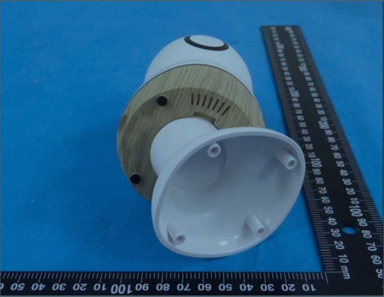
MNJ-MO180TX
Mar 29, 2023Smart Baby Monitor
Equipment Class
DTS - Digital Transmission System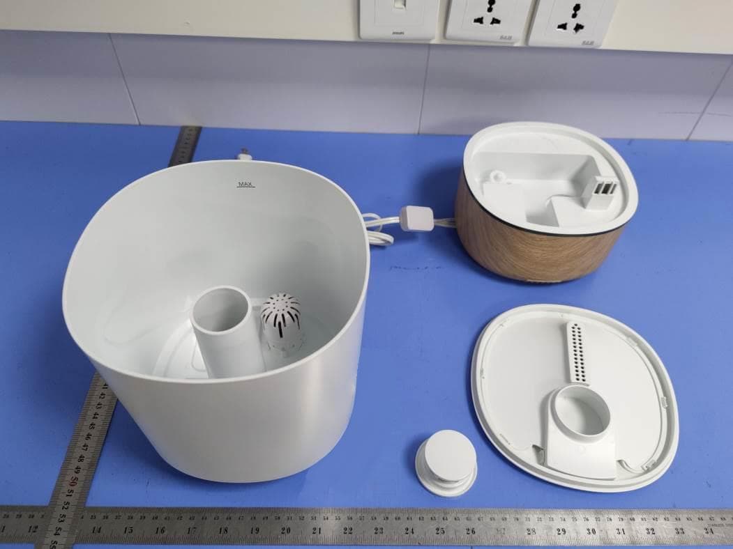
MNJ-IH555
Aug 11, 2021Humidifier
Equipment Class
DTS - Digital Transmission System
MNJ-MO173TX
Jun 06, 2021Baby Monitor
Equipment Class
DTS - Digital Transmission System