MNJ48018TBaby Monitor
Dorel Juvenile Group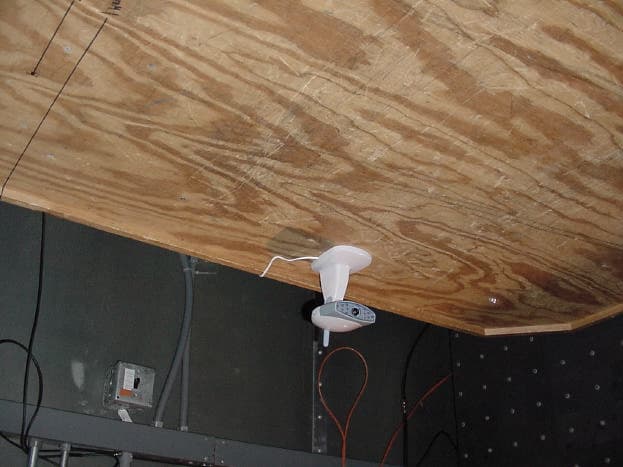
Click to zoom
Application Details
- Equipment Class
- DXX - Part 15 Low Power Communication Device Transmitter
- Date of Grant
- Jan 18, 2001
- Application Purpose
- Original Equipment
- Date of Application
- Jan 18, 2001
- Equipment Note
- Baby Monitor
- Frequency Range
- 902.00000000 - 928.00000000
- Company
- Dorel Juvenile Group
- Country
- United States
Documents & Files
Document Text
Text extracted from the exhibit documents filed with the FCC. Open a document above to read the original.
Users Manual
A B C Page 1 900 MHz Sound & Sight Television Monitor No. 48018 Owner’s Manual Introduction Thank you for purchasing the Safety 1st 900 MHz Sound & Sight Television Monitor. We are confident that this revolutionary monitoring system will help keep you in tune with your baby’s sounds and activity. The 900 MHz Sound & Sight Television Monitor can turn any TV into a nursery monitor, transmitting crisp sound and a clear, black and white image with the touch of your remote control. The system is compatible with “picture- in-picture” televisions, and two Base Units are included for use with two TV’s. The camera is easy to install, can be wall or table-top mounted, and features infrared LED’s to always give you a clear view of baby – even in a darkened nursery. The 900 MHz Sound & Sight Television Monitor can also be used as an audio monitor. The audio monitor Receiver features sound lights to show your baby’s sound level, both while connected to your TV and while in portable mode. The receiver can be run on household electricity or on battery power. Please read all instructions carefully before using this product. Keep these instructions for future reference. If you have any questions, please call our Consumer Relations number at (800)723-3065. In Canada call (800)387-2229. CAUTION: • THE 900 MHZ SOUND & SIGHT TELEVISION MONITOR IS NOT INTENDED TO REPLACE RESPONSIBLE AND PROPER PARENTAL SUPERVISION. • YOU SHOULD CHECK YOUR CHILD’S ACTIVITY AT REGULAR INTERVALS AS THIS MONITOR WILL NOT ALERT PARENTS TO THE SILENT ACTIVITIES OF A CHILD. 48018 sights & sounds 11/7/00 12:13 PM Page 1 Table of Contents Important Safety Messages . . . . . . . . . . . . . . . . . . . . . . . . . . . . . . . . . . . . . . . . . . . . . . . . . . . . . . . . . . . . . . . . . . . . . . . . . . . . . .2 – 3 Care and Maintenance . . . . . . . . . . . . . . . . . . . . . . . . . . . . . . . . . . . . . . . . . . . . . . . . . . . . . . . . . . . . . . . . . . . . . . . . . . . . . . . . . . .3 Requirements . . . . . . . . . . . . . . . . . . . . . . . . . . . . . . . . . . . . . . . . . . . . . . . . . . . . . . . . . . . . . . . . . . . . . . . . . . . . . . . . . . . . . . . . . .4 Contents . . . . . . . . . . . . . . . . . . . . . . . . . . . . . . . . . . . . . . . . . . . . . . . . . . . . . . . . . . . . . . . . . . . . . . . . . . . . . . . . . . . . . . . . . . . . . .4 Features and Components . . . . . . . . . . . . . . . . . . . . . . . . . . . . . . . . . . . . . . . . . . . . . . . . . . . . . . . . . . . . . . . . . . . . . . . . . . . . . .4 – 5 Battery Installation . . . . . . . . . . . . . . . . . . . . . . . . . . . . . . . . . . . . . . . . . . . . . . . . . . . . . . . . . . . . . . . . . . . . . . . . . . . . . . . . . . . . . .5 Camera Location and Set Up . . . . . . . . . . . . . . . . . . . . . . . . . . . . . . . . . . . . . . . . . . . . . . . . . . . . . . . . . . . . . . . . . . . . . . . . . . . . . . .6 Camera Operation . . . . . . . . . . . . . . . . . . . . . . . . . . . . . . . . . . . . . . . . . . . . . . . . . . . . . . . . . . . . . . . . . . . . . . . . . . . . . . . . . . . .6 – 7 Receiver and Base Unit Set Up/Operation . . . . . . . . . . . . . . . . . . . . . . . . . . . . . . . . . . . . . . . . . . . . . . . . . . . . . . . . . . . . . . . . . . . . . .8 Options for Set Up to a TV . . . . . . . . . . . . . . . . . . . . . . . . . . . . . . . . . . . . . . . . . . . . . . . . . . . . . . . . . . . . . . . . . . . . . . . . . . . . . . .8 – 9 Using the Second Base Unit . . . . . . . . . . . . . . . . . . . . . . . . . . . . . . . . . . . . . . . . . . . . . . . . . . . . . . . . . . . . . . . . . . . . . . . . . . . . . . . .9 Using Portable Parent’s Unit . . . . . . . . . . . . . . . . . . . . . . . . . . . . . . . . . . . . . . . . . . . . . . . . . . . . . . . . . . . . . . . . . . . . . . . . . . . . . . . .9 Testing Reception . . . . . . . . . . . . . . . . . . . . . . . . . . . . . . . . . . . . . . . . . . . . . . . . . . . . . . . . . . . . . . . . . . . . . . . . . . . . . . . . . . . . . .10 Important Notes . . . . . . . . . . . . . . . . . . . . . . . . . . . . . . . . . . . . . . . . . . . . . . . . . . . . . . . . . . . . . . . . . . . . . . . . . . . . . . . . . . . . . . .10 Troubleshooting . . . . . . . . . . . . . . . . . . . . . . . . . . . . . . . . . . . . . . . . . . . . . . . . . . . . . . . . . . . . . . . . . . . . . . . . . . . . . . . . . . . . . . .11 Important Safety Messages TO REDUCE THE RISK OF ELECTRICAL SHOCK, DO NOT REMOVE COVER OR BACK. NO SERVICEABLE PARTS INSIDE. REFER SERVICING TO SAFETY 1ST CONSUMER RELATIONS (800) 723-3065. IN CANADA CALL (800)387-2229. TO REDUCE THE RISK OF FIRE OR ELECTRICAL SHOCK, DO NOT EXPOSE THIS PRODUCT TO WATER OR MOISTURE. NEVER ATTEMPT TO OPEN THE CASE OF EITHER THE CAMERA OR MONI- TOR. THIS IS DANGEROUS AND WILL VOID THE WARRANTY. WARNING Page 2 CAUTION SAFETY INSTRUCTIONS 1. Before using your Safety 1st 900 MHz Sound & Sight Television Monitor: • Read and follow all instructions carefully. • Read and observe all warnings on the product and in this instruction booklet. 2. To prevent entanglement with the adapter cord,NEVERplace the Camera in or near a crib or playpen.DO NOTplace the Camera on any surface or mount it on any wall where the Camera or its AC adapter cord are within reach of children. 48018 sights & sounds 11/7/00 12:13 PM Page 2 3.ALWAYS KEEP THE CAMERA, RECEIVER (PARENT'S UNIT), AND AC ADAPTERS OUT OF REACH OF CHILDREN. DO NOT MOUNT IN OR ON CRIB! 4. This product is not intended to be used as a medical monitor and its use should not replace adult supervision. It is important that an adult stay within the viewing range of the 900 MHz Sound & Sight Television Monitor at all times during use. 5. It is essential to check reception regularly. Please see the Reception section for complete instructions. 6. NEVER use the Camera or Receiver near water. For example, do not use near a bathtub, bathroom sink, laun…
Text truncated - open the document above for the full version.
Block Diagram
Model : 48018 Block Diagram Date :10-Jan-2000 Ant. Cmos Sensor Mic Operational Sequence: The model 48018 is a video baby monitor transmitter, which operates at 902-928MHz. The signal format follow the regular NTSC TV video signal, which is the video signal is modulated in AM, and the sound signal is in 4.5MHz FM apart from the main carrier. The circuitry consist of a RF integrated circuit (U2 RF2504) which forms the main RF oscillator. The oscillation frequency is mainly control by a coaxial resonator L2. The varistor D1 is connected parallelly to the resonator, and it's capacitance can vary the resonance frequency of coaxial resonator slightly so that three different frequencies can be generated for three channels. The picture is picked up by a Cmos Camera Module OV5116, and the IC will turn the picture into a analog video composite signal. The Module also contain 12 pcs of Infra-red LEDs for automatic night-light purpose. The video composite signal will go thru Q2 and Q3 and then modulated into the carrier in AM format. The sound will be picked up by a microphone, and then go thru a AGC amplifier Q5, Q6 Q7, Q8, and then modulated in a 4.5Mhz sound IF carrier by Q4 and Q20. Finally, this sound IF carrier will be combined into the main carrier as well. There is a Video On/Off switch provided on the circuitry. in OFF position, the video modulation will be disabled and only the sound carrier output will function. Finally, the RF signal coupled to a spiral antenna thru a stripline transformer/filter. RF output Amplifier Q1 RF Oscillator U2,Q19 Frequencies 909MHz 916MHz 922MHz AM (Video) Modulator Q2, Q3 Mic Amplifier with AGC Q7, Q5, Q8, Q6 4.5MHz Sound Carrier Oscillator with Sound FM Modulator Q4, Q20 + D2 Cmos Camera Module OV5116 with Night Light circuit Q15, 16 &17 Stripline Filter Video On/ Off (S4)
Cover Letter(s)
safety1st tcb confidential (2550x3302x256 jpeg)
External Photos
FCC ID: MNJ48018T Compliance Worldwide, Inc. - 357 Main Street - Sandown, NH 03873 (603) 887 3903 Fax 887 6445 http://www.cw-inc.com TEST NUMBER - 381-00 PHOTOGRAPHS Radiated Test Setup (Front) FCC ID: MNJ48018T Compliance Worldwide, Inc. - 357 Main Street - Sandown, NH 03873 (603) 887 3903 Fax 887 6445 http://www.cw-inc.com TEST NUMBER - 381-00 PHOTOGRAPHS Radiated Test Setup (Rear) FCC ID: MNJ48018T Compliance Worldwide, Inc. - 357 Main Street - Sandown, NH 03873 (603) 887 3903 Fax 887 6445 http://www.cw-inc.com TEST NUMBER - 381-00 PHOTOGRAPHS Conducted Test Setup (Front) FCC ID: MNJ48018T Compliance Worldwide, Inc. - 357 Main Street - Sandown, NH 03873 (603) 887 3903 Fax 887 6445 http://www.cw-inc.com TEST NUMBER - 381-00 PHOTOGRAPHS Conducted Test Setup (Rear)
ID Label/Location Info
Compliance Worldwide, Inc. - 357 Main Street - Sandown, NH 03873 (603) 887 3903 Fax 887 6445 http://www.cw-inc.com 381-00 FCC ID: MNJ48018T Photo of FCC label location. Compliance Worldwide, Inc. - 357 Main Street - Sandown, NH 03873 (603) 887 3903 Fax 887 6445 http://www.cw-inc.com 381-00 FCC ID: MNJ48018T Photo of FCC label text. The label on the product is readily legible without the aid of magnification.
Internal Photos
FCC ID: MNJ48018T Compliance Worldwide, Inc. - 357 Main Street - Sandown, NH 03873 (603) 887 3903 Fax 887 6445 http://www.cw-inc.com TEST NUMBER - 381-00 PHOTOGRAPHS Interior Product Photographs (Assembled Interior Top) FCC ID: MNJ48018T Compliance Worldwide, Inc. - 357 Main Street - Sandown, NH 03873 (603) 887 3903 Fax 887 6445 http://www.cw-inc.com TEST NUMBER - 381-00 PHOTOGRAPHS Interior Circuit Board Photographs(Camera/LED/Microphone board Front) FCC ID: MNJ48018T Compliance Worldwide, Inc. - 357 Main Street - Sandown, NH 03873 (603) 887 3903 Fax 887 6445 http://www.cw-inc.com TEST NUMBER - 381-00 PHOTOGRAPHS Interior Circuit Board Photographs(Camera/LED/Microphone board Rear) FCC ID: MNJ48018T Compliance Worldwide, Inc. - 357 Main Street - Sandown, NH 03873 (603) 887 3903 Fax 887 6445 http://www.cw-inc.com TEST NUMBER - 381-00 PHOTOGRAPHS Interior Circuit Board Photographs(Antenna) FCC ID: MNJ48018T Compliance Worldwide, Inc. - 357 Main Street - Sandown, NH 03873 (603) 887 3903 Fax 887 6445 http://www.cw-inc.com TEST NUMBER - 381-00 PHOTOGRAPHS Interior Circuit Board Photographs(Main board bottom) FCC ID: MNJ48018T Compliance Worldwide, Inc. - 357 Main Street - Sandown, NH 03873 (603) 887 3903 Fax 887 6445 http://www.cw-inc.com TEST NUMBER - 381-00 PHOTOGRAPHS Interior Circuit Board Photographs(Main board Top w/RF board removed) FCC ID: MNJ48018T Compliance Worldwide, Inc. - 357 Main Street - Sandown, NH 03873 (603) 887 3903 Fax 887 6445 http://www.cw-inc.com TEST NUMBER - 381-00 PHOTOGRAPHS Interior PCB Photographs(RF board bottom removed from Main board) FCC ID: MNJ48018T Compliance Worldwide, Inc. - 357 Main Street - Sandown, NH 03873 (603) 887 3903 Fax 887 6445 http://www.cw-inc.com TEST NUMBER - 381-00 PHOTOGRAPHS Interior PCB Photographs(RF board Top removed from main board) FCC ID: MNJ48018T Compliance Worldwide, Inc. - 357 Main Street - Sandown, NH 03873 (603) 887 3903 Fax 887 6445 http://www.cw-inc.com TEST NUMBER - 381-00 PHOTOGRAPHS Interior Photographs (Interior w/PCBs removed) FCC ID: MNJ48018T Compliance Worldwide, Inc. - 357 Main Street - Sandown, NH 03873 (603) 887 3903 Fax 887 6445 http://www.cw-inc.com
Operational Description
Model : 48018 Block Diagram Date :10-Jan-2000 Ant. Cmos Sensor Mic Operational Sequence: The model 48018 is a video baby monitor transmitter, which operates at 902-928MHz. The signal format follow the regular NTSC TV video signal, which is the video signal is modulated in AM, and the sound signal is in 4.5MHz FM apart from the main carrier. The circuitry consist of a RF integrated circuit (U2 RF2504) which forms the main RF oscillator. The oscillation frequency is mainly control by a coaxial resonator L2. The varistor D1 is connected parallelly to the resonator, and it's capacitance can vary the resonance frequency of coaxial resonator slightly so that three different frequencies can be generated for three channels. The picture is picked up by a Cmos Camera Module OV5116, and the IC will turn the picture into a analog video composite signal. The Module also contain 12 pcs of Infra-red LEDs for automatic night-light purpose. The video composite signal will go thru Q2 and Q3 and then modulated into the carrier in AM format. The sound will be picked up by a microphone, and then go thru a AGC amplifier Q5, Q6 Q7, Q8, and then modulated in a 4.5Mhz sound IF carrier by Q4 and Q20. Finally, this sound IF carrier will be combined into the main carrier as well. There is a Video On/Off switch provided on the circuitry. in OFF position, the video modulation will be disabled and only the sound carrier output will function. Finally, the RF signal coupled to a spiral antenna thru a stripline transformer/filter. RF output Amplifier Q1 RF Oscillator U2,Q19 Frequencies 909MHz 916MHz 922MHz AM (Video) Modulator Q2, Q3 Mic Amplifier with AGC Q7, Q5, Q8, Q6 4.5MHz Sound Carrier Oscillator with Sound FM Modulator Q4, Q20 + D2 Cmos Camera Module OV5116 with Night Light circuit Q15, 16 &17 Stripline Filter Video On/ Off (S4)
Test Report
Compliance Worldwide, Inc. – 357 Main Street – Sandown, NH 03873 (603) 887 3903 Fax 887 6445 http://www.cw-inc.com TEST NUMBER - 381-00 TESTING TO INDUSTRY CANADA RSS 210 SECTION 6.2.2 FEDERAL COMMUNICATIONS COMMISSION CFR47 PART 15.249 Low Power License-Exempt Radiocummunication Devices Intentional Radiators for Safety 1st , Inc. 45 Dan Road Canton ,MA 02021 1-800-962-7233 of Sound N Sight TV Monitor Transmitter 48018 FCC ID: MNJ48018T on 1/4/2001 Tested by _____________________________________ Clifton P. Brick Reviewed by _____________________________________ Larry K. Stillings Page 2 of 38 Compliance Worldwide, Inc. – 357 Main Street – Sandown, NH 03873 (603) 887 3903 Fax 887 6445 http://www.cw-inc.com TEST NUMBER - 381-00 TABLE OF CONTENTS • Test Description • Test Results and Conclusions • Test Procedures • RSS 210 /Part 15 Subpart C Test Limits • Test Facility Description • Test Setup and Connection Information • Test Measurements and Results Radiated Measurements Radiated Output Power Conducted Measurements • Notes and Comments Page 3 of 38 Compliance Worldwide, Inc. – 357 Main Street – Sandown, NH 03873 (603) 887 3903 Fax 887 6445 http://www.cw-inc.com TEST NUMBER - 381-00 TEST DESCRIPTION 1. TEST OBJECTIVE To test the Sound N Sight TV Monitor Transmitter 48018 to RSS 210 / Part 15 Subpart C Rules and write a report. 2. E.U.T. DESCRIPTION GENERAL The Sound N Sight TV Monitor Transmitter 48018 is a 900 MHz baby nursery monitor transmitter. The transmitter is part of a system that sends an audio and video signal from the nursery to a remote receiver that can be connected to a television to provide a video output. SERIAL NUMBERS: Pre Production Prototype Page 4 of 38 Compliance Worldwide, Inc. – 357 Main Street – Sandown, NH 03873 (603) 887 3903 Fax 887 6445 http://www.cw-inc.com TEST NUMBER - 381-00 TEST RESULTS AND CONCLUSIONS PRODUCT TESTED - Sound N Sight TV Monitor, Transmitter MODEL NUMBER - 48018 RADIATED TEST RESULTS The test results show that the emissions radiated from this equipment are in compliance with IC Rules RSS 210 / FCC Rules Part 15 Subpart C. OCCUPIED BANDWIDTH & OUTPUT POWER The test results show that the occupied bandwidth and output power of this equipment are in compliance with IC Rules RSS 210 / FCC Rules Part 15 Subpart C . CONDUCTED TEST RESULTS The test results show that the emissions conducted through the power line from this equipment are in compliance with IC Rules RSS 210 / FCC Rules Part 15 Subpart C. ANALYSIS AND CONCLUSIONS Based upon the radiated and conducted measurements we find that this equipment is within the limits of the IC Rules RSS 210 / FCC Rules Part 15 Subpart C. All results are based on a test of one sample, and represent other production units, only in as much as a sample represents other production units. If any significant changes are made to the unit, the changes shall be evaluated and a retest may be required. NOTES (Special conditions unique to this test) Please note the last paragraph of page 7. The antenna wire is soldered to the PCB, no connector is used. The FCC Label information will be engraved in the mold. Power input was varied +/-15% with no change in output power. EUT was examined in 3 orthogonal planes, worst case is as shown in setup photos. Page 5 of 38 Compliance Worldwide, Inc. – 357 Main Street – Sandown, NH 03873 (603) 887 3903 Fax 887 6445 http://www.cw-inc.com TEST NUMBER - 381-00 TEST PROCEDURES 1. TEST EQUIPMENT A. HP 8546A (9 kHz - 6.5 GHz) EMI Receiver w/ RF Filter Section, S/N 3704A00323 / 3650A00360. Calibration Date 7-18-2000, calibrated annually. B. HP 8593E (9 kHz - 26.5 GHz) Spectrum Analyzer, S/N 3829A03887. Calibration Date 10-21-2000, calibrated annually. C. Electro-Metrics BiConical Antenna, Model EM6912A, S/N 149. Calibration Date 2-22-2000, calibrated annually. D. Electro-Metrics Log Periodic Antenna, Model EM-6950, S/N 1017. Calibration Date: 2-22-2000, calibrated annually. E. Com Power Double Ridged Guide Antenna, Model AH 118, S/N 10078. Calibration Date: 8-11-2000, calibrated annually. F. HP 1 - 26.5 GHz Preamplifier, Model 08449B, S/N 3008A01323. Calibration Date: 10-21-2000, calibrated annually. G. LISN, Compliance Worldwide, Model 50 μH / 50 ohm, S/N 100. Calibration Date 2-22-2000, calibrated annually. 2. FREQUENCY RANGE TO BE SCANNED. A. Radiated Test from 30 MHz to 40 GHz (or the 10 th harmonic of the highest frequency whichever is lower). B. Conducted Test from 450 kHz to 30 MHz. Page 6 of 38 Compliance Worldwide, Inc. – 357 Main Street – Sandown, NH 03873 (603) 887 3903 Fax 887 6445 http://www.cw-inc.com TEST NUMBER - 381-00 3. TEST PROCEDURES. Radiated test procedure: The EUT, associated cables and peripheral devices are placed on the supporting table and any support equipment is placed off the site. The EUT is turned on and any necessary operating or test software installed and allowed to warm up. The frequency band from 30 MHz to 40 GHz is scanned. When an emission is found the emission is maximized by varying the bundle position of the connecting cables, the antenna height, the antenna polarization (vertical and horizontal) and the table orientation (360 degrees). The maximum reading is recorded and the next signal is searched for. Conducted test procedure: The power line of the EUT is connected to the LISN (Line Impedance Stabilization Network). A measurement of the emissions are made from the power line for both phase and neutral on the analyzer in the frequency range from 450 kHz to 30 MHz. The maximum readings are recorded for each phase. All measurements are made according to the procedures defined in: "ANSI C63.4-1992 Standard Methods of Measurement of Radio Noise Emissions from Low-Voltage Electrical and Electronics Equipment in the Range of 9 kHz to 40 GHz, American National Standard (ISBN 1- 55937-215-5). Page 7 of 38 Compliance Worldwide, Inc. – 357 Main Street – Sandown, NH 03873 (603) 887 3903 Fax 887 6445 http://www.cw-inc.com TEST NUMBER - 381-00 RSS 210 TEST LIMI…
Text truncated - open the document above for the full version.
Test Setup Photos
FCC ID: MNJ48018T Compliance Worldwide, Inc. - 357 Main Street - Sandown, NH 03873 (603) 887 3903 Fax 887 6445 http://www.cw-inc.com TEST NUMBER - 381-00 PHOTOGRAPHS Radiated Test Setup (Front) FCC ID: MNJ48018T Compliance Worldwide, Inc. - 357 Main Street - Sandown, NH 03873 (603) 887 3903 Fax 887 6445 http://www.cw-inc.com TEST NUMBER - 381-00 PHOTOGRAPHS Radiated Test Setup (Rear) FCC ID: MNJ48018T Compliance Worldwide, Inc. - 357 Main Street - Sandown, NH 03873 (603) 887 3903 Fax 887 6445 http://www.cw-inc.com TEST NUMBER - 381-00 PHOTOGRAPHS Conducted Test Setup (Front) FCC ID: MNJ48018T Compliance Worldwide, Inc. - 357 Main Street - Sandown, NH 03873 (603) 887 3903 Fax 887 6445 http://www.cw-inc.com TEST NUMBER - 381-00 PHOTOGRAPHS Conducted Test Setup (Rear)
Contact Information
Applicant
Dan Desimone(Director R & A, Project Management)
Technical Contact
Compliance Worlwide, IncLarry K Stillings
[email protected]603 887 3903
357 Main Street · Sandown, New Hampshire · United States
Non-Technical Contact
Compliance Worlwide, IncLarry K Stillings
[email protected]603 887 3903
Test Firm
Compliance Worldwide, Inc.Larry Stillings
Technical Specifications
| # | Rule Parts | Frequency Range | Power Output |
|---|---|---|---|
| 1 | 15C | 902 MHz - 928 MHz | - |
Other Applications from Dorel Juvenile Group
MNJ-MO191
Apr 09, 2024CryAssist Audio Monitor
Equipment Class
DSS - Part 15 Spread Spectrum Transmitter
MNJ-MO183TX
Dec 05, 2023See Pro 360 Baby Monitor
Equipment Class
NII - Unlicensed National Information Infrastructure TX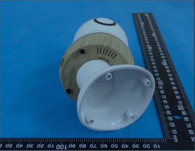
MNJ-MO180TX
Mar 29, 2023Smart Baby Monitor
Equipment Class
DTS - Digital Transmission System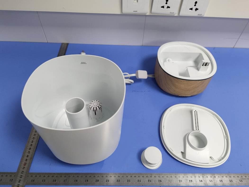
MNJ-IH555
Aug 11, 2021Humidifier
Equipment Class
DTS - Digital Transmission System
MNJ-MO173TX
Jun 06, 2021Baby Monitor
Equipment Class
DTS - Digital Transmission System