MNJ49233TLow power UHF transmitter
Dorel Juvenile Group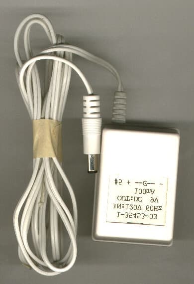
Click to zoom
Application Details
- Equipment Class
- DXX - Part 15 Low Power Communication Device Transmitter
- Date of Grant
- Jan 05, 1999
- Application Purpose
- Original Equipment
- Date of Application
- Nov 11, 1998
- Equipment Note
- Low power UHF transmitter
- Frequency Range
- 49.85000000 - 49.87000000
- Company
- Dorel Juvenile Group
- Country
- United States
Documents & Files
Document Text
Text extracted from the exhibit documents filed with the FCC. Open a document above to read the original.
Users Manual
We are sure that you will find the Clear Connection Nursery Monitor convenient and easy to use. To insure that you will benefit fro m all of the great features that our monitor offers, and to make sure that it is used pro p e r l y, we urge you to: Clear Connection Rechargeable Nursery Monitor O w n e r’s Guide Thank you for purchasing the Safety 1 s t Clear Connection Rechargeable Nursery M o n i t o r. This is a state-of-the-art system that combines some of the most unique f e a t u res that any baby monitor offers. We are confident that you will appre c i a t e its many highlights. As you will soon learn there are many more feature s . . . The Baby’s Unit (Transmitter) has continuous transmission that clearly sends your baby’s sounds to the Pare n t ’s Unit. This gives you the ability to continue with your daily activities throughout the house or yard and at the same time monitor your baby. The Pare n t ’s Unit (Receiver) remains with you wherever you go to pick up the sounds that are transmitted from the Baby’s Unit. It conveniently clips to your belt or easily stands on a table. Both units are completely portable or AC powered. The AC Adapter allows the receiver and transmitter to be plugged into any standard electrical outlet for use with your household electricity. For convenient use without an outlet, use a re c h a rgeable battery pack for the Pare n t ’s unit and a 9 volt alkaline battery for the Baby’s unit (Batteries not included). PLEASE READ ALL INSTRUCTIONS CAREFULLY BEFORE USING THE NURSERY MONITOR KEEP THESE INSTRUCTIONS FOR YOUR FUTURE REFERENCE IF YOU HAVE ANY QUESTIONS, CALL OUR TOLL FREE CONSUMER RELATIONS NUMBER: (800) 723-3065 No. 49233 CAU T I O N : • THE CLEAR CONECTION RECHARGEABLE NURSERY MONITOR IS NOT INTENDED TO REPLACE RESPONSIBLE AND PROPER PA R E N TAL SUPERV I S I O N . • YOU SHOULD CHECK YOUR CHILD’S ACTIVITY AT REGULAR INTERVALS AS THIS MONITOR WILL NOT ALERT PARENTS TO THE SILENT ACTIVITIES OF A CHILD. C AU T I O N RISK OF ELECTRIC SHOCK DO NOT OPEN! CAU T I O N :TO REDUCE THE RISK OF ELECTRICAL SHOCK, DO NOT REMOVE COVER OR BAC K . NO SERVICEABLE PA RTS INSIDE. REFER TO SAFETY 1 S T CONSUMER RELAT I O N S :(800) 723-3065. WA R N I N G :TO REDUCE THE RISK OF FIRE OR ELECTRICAL SHOCK, DO NOT EXPOSE THIS PRODUCT TO WATER OR MOISTURE. Sa fe ty Instru ct i o n s READ INSTRU C T I O N S :All the safety instructions should be read before the Nursery Monitor is operated. R E TAIN INSTRU C T I O N S :The safety instructions should be retained for future re f e re n c e . HEED WA R N I N G S :All warnings on the Nursery Monitor and operating instructions should be adhered to. F O L LOW INSTRU C T I O N S :All operating instructions should be followed. Fe at u res and Co m po n e nt s WATER AND MOISTURE:The Nursery Monitor should not be used near water, for example, near a bath tub, wash bowl, kitchen sink, laundry tub, in a wet basement, near a swimming pool, etc. V E N T I LAT I O N:The Nursery Monitor should be placed so that its location or position does not interf e re with proper ventilation for the unit. For example, it should N E V E Rbe situated on a bed, sofa, rug or similar surface that may block ventilation. H E AT:The Nursery Monitor should be kept away from heat sources such as radiators, heat registers, stoves or other appliances that produce heat. AC POWER SOURC E :The Nursery Monitor should be connected only to the AC Adapters supplied with the unit. P OWER CORD PROT E C T I O N :The power supply cord should be routed so that it is not likely to be walked on or pinched by items placed upon or against it. Pay particular attention to the cord at the plug, convenience receptacle, and at the point it exits from the AC adapters. C L E A N I N G :Use a dry cotton cloth to keep the Nursery Monitor free from dust. DO NOT USE WAT E R! NON-USE PERIODS:The power cord of the Nursery Monitor should be unplugged from the outlet when unused for long periods of time. The batteries should also be removed during these periods. OBJECT AND LIQUID ENTRY:C a re should be taken so that objects do not fall onto the product, and liquids are not spilled into the enclosure through the openings. D A M AGE REQUIRING SERV I C E :The Nursery Monitor should be serviced by qualified personnel when: A :The power supply cord or plug has been damaged; B :Objects have fallen or liquid has been spilled onto the pro d u c t ; C :The Monitor has been exposed to rain; D :The Monitor does not appear to operate normally or exhibits a marked change in its perf o rm a n c e ; E :The Monitor has been dropped or the enclosure damaged. THE USER SHOULD NOT ATTEMPT TO SERVICE OR REPAIR THE MONITO R .ALL SERVICING SHOULD BE REFERRED TO S A F E TY 1 S T CONSUMER RELAT I O N S :(800) 723-3065. KEEP ALL PA RTS OF THIS MONITOR OUT OF REACH OF CHILDREN! DO NOT MOUNT IN OR ON CRIB! CAU T I O N :THE CLEAR CONNECTION RECHARGEABLE NURSERY MONITOR IS NOT INTENDED TO REPLACE P ROPER ADULT SUPERV I S I O N .YOU SHOULD CHECK YOUR CHILD’S AC T I V I TY AT REGULAR I N T E RVALS AS THIS MONITOR WILL NOT ALERT PA R E N TS TO THE SILENT ACTIVITIES OF A CHILD. Co nte nt s Parent’s Unit (Receiver)Baby’s Unit (Transmitter) Recharging StandAC Adapter On/Off/Volume Switch Channel Switch Sound Lights Plastic Belt Clip Compartment for Rechargeable Battery Speaker Low Battery Indicator (Red) Power On Indicator (Green) Flexible Antenna Battery contact for Recharger Follow these instructions to operate your Clear Connection Rechargeable Monitor. Reference the illustrations provided on pages 2 and 3 for the location of all features described in these instructions. Ba by’s Un i t : STEP 1Remove screw from battery cover on Baby’s Unit (Transmitter) and remove cover. STEP 2I n s e rt a 9-volt battery into the battery compartment by snapping the battery con- tacts into the corresponding connectors on the battery clip in the unit. (Figure 1) No te :The low battery indicator illuminates when the batteries need to be re p l a c e…
Text truncated - open the document above for the full version.
Cover Letter(s)
Letter of AuthorizationFCC ID:MNJ49233T
Cover Letter(s)
Confidentiality Letter FCC ID: MNJ49233T
External Photos
External PhotosFCC ID: MNJ49233T
ID Label/Location Info
FCC ID: MNJ49233T FCC Label FCC ID Label 1.918 x 0.833” Permanently Engraved on Rear of EUT Location of Label on EUT Rear of the EUT FCC ID: MNJ49233T © 1998 Safety 1st All Rights Reserved Made in China THIS DEVICE COMPLIES W ITH PART 15 OF THE FCC RULES. OPER- ATIONIS SUBJECT TO THE FOLLOW ING TWO CONDITIONS: (1) THIS DEVICE MAY NOT CAUSE HARMFUL INTERFERENCE, AND (2) THIS DEVICE MUST ACCEPT ANY INTERFERENCE RECEIVED, INCLUDING INTERFERENCE THAT MAY CAUSE UNDESIRED OPERATION. CANADA: 210 © 1998 Safety 1st Tous les droits sont réservés. Fabriqué en Chine. CET APPAREIL EST CONFORME À LA PARTIE 15 DU RÈGLEMENT DE LA FCC. LE FONCTIONNEMENT EST SUJET AUX DEUX CONDITIONS SUIVANTES: (1) CET APPAREIL NE PEUT CAUSER D'INTERFÉRENCES NUISIBLES ET (2) CET APPAREIL REÇOIT TOUTE INTERFÉRENCE MÊME LES INTERFÉRENCES QUI PEUVENT OCCASIONER UN MAUVAIS FONCTIONNEMENT. FCC Label
Internal Photos
Internal PhotosFCC ID: MNJ49233T
Test Report
Low Power UHF Transmitter Radiometrics Midwest Corporation Test Document RP-3902 Issue Date: November 16, 1998 This report concerns: Original grant Equipment type: Low Power Transmitter Transition Rules per 15.37 are not requested. Tests Performed ForTest Facility Safety 1st, Inc. 210 Boyleston St. Chestnut Hill, Massachusetts 02167 Radiometrics Midwest Corporation 12 East Devonwood Romeoville, IL 60446 Phone: (815) 293-0772 FAX: (815) 293-0820 [email protected] Test Report Written ByTest Report Approved By Joseph Strzelecki Senior EMC Engineer NARTE EMC-000877-NE Chris W. Carlson Director of Engineering NARTE EMC-000921-NE MEASUREMENT/TECHNICAL REPORT Safety 1st, Inc. Model 49233 FCC ID: MNJ49233T APPLICATION FOR CERTIFICATION RF Emission Measurements Performed For Determination of Compliance with the US Code of Federal Regulations Title 47, Chapter I, FCC Part 15 Subpart B As Required for Certification for Unintentional Radiators Tests Performed ForFCC IDRadiometrics Test DocumentPage Safety 1st, Inc. MNJ49233TRP-39022 of 11 Table of Contents Notice: This report must not be reproduced (except in full) without the written approval of Radiometrics Midwest Corporation. Tests Performed ForFCC IDRadiometrics Test DocumentPage Safety 1st, Inc. MNJ49233TRP-39023 of 11 1.0 General Information 1.1 Product Description The Model 49233T (referred to as the EUT in this report) is a Low Power VHF Transmitter. The EUT is manufactured by Safety 1st, Inc. 1.2 Related Submittals Safety 1st, Inc. is not submitting any other submittals related to the EUT. The associated receiver is operated under part 15. It is subject to the FCC requirements pursuant to the Certification equipment authorization under Part 15 Subpart B, and will be submitted as FCC ID: MNJ49233R. 1.3 Tested System Details The FCC ID's for all equipment, plus descriptions of all cables used in the tested system which have grants, are: Model Number Serial NumberFCC ID Manufacturer & Description Cable Descriptions M/N: 49233 (EUT)MNJ49233TSafety 1st, Inc. Low Power VHF Transmitter Power (1.8m, US) from transformer to EUT Note: SH = Shielded; US = Unshielded; m = Cable Length in Meters, 1.4 Test Methodology The test procedures used are in accordance with the ANSI document C63.4-1992, (July 17, 1992) "Methods of Measurement of Radio Noise Emissions from Low-Voltage Electrical and Electronic Equipment in the Range of 9 kHz to 40 GHz". The specific procedures are described herein. Radiated testing was performed at an antenna to EUT distance of 3 meters. The antenna was raised and lowered from 1 to 4 meters. 1.5 Test Facility The open area test site used to collect the radiated data is located on 8625 Helmar Road in Newark, Illinois. The open field test site has a metal ground screen. Details of the site characteristics are on file with the FCC. Conducted emission measurements and preliminary radiated emission scans were performed in shielded enclosure “A” at Radiometrics' Romeoville, Illinois EMI test lab. These sites have been fully described in a report and accepted by the FCC in a letter dated October 1, 1996 (31040/SIT 1300F2). Conducted emission measurements were performed using a Line Impedance Stabilization Network (LISN) as the pick-up device. This device is constructed in accordance with the circuit diagram provided in Figure 3 of ANSI document C63.4-1992. Tests Performed ForFCC IDRadiometrics Test DocumentPage Safety 1st, Inc. MNJ49233TRP-39024 of 11 1.6 Test Equipment Radiated emission measurements were performed with linearly polarized broadband antennas. The results obtained with these antennas can be correlated with results obtained with a tuned dipole antenna. Below 1 GHz, when a radiated emission is detected approaching the specification limit, the measurement of the emission is repeated using a tuned dipole antenna with a Roberts Balun. The radiated emission measurements were performed with a spectrum analyzer. The bandwidths of the spectrum analyzers are adjusted to the correct bandwidths as specified by the FCC Rules. The bandwidth used from 450 kHz to 30 MHz is 10 kHz and the bandwidth from 30 MHz to 1000 MHz is 100 or 120 kHz. Above 1 GHz a 1 MHz bandwidth is used. In order to increase the sensitivity of the spectrum analyzer, a preamplifier was used. The preamplifiers used had sufficient dynamic range that ensured that an overload condition was not present during the tests. 2.0 System Test Configuration 2.1 Test System and Justification Wiring was consistent with manufacturer's recommendations. The system was configured for testing in a typical fashion (as a customer would normally use it). Power was supplied at 115 VAC, 60 Hz single-phase to its external power supply. 2.2 EUT Test Configuration The EUT was tested as a stand-alone device. The EUT was in continuous transmit mode for testing 2.3 Special Accessories No special accessories were used during the tests in order to achieve compliance. 2.4 Equipment Modifications No modifications were made to the EUT at Radiometrics' test facility in order to comply with the standards listed in this report. Tests Performed ForFCC IDRadiometrics Test DocumentPage Safety 1st, Inc. MNJ49233TRP-39025 of 11 Figure 2.1 Configuration of Tested System Rotating Platform: 1x1.5m surface above GND plane Antenna For Radiated Emissions Preamp LISN AC Mains EUT Conducted Emissions: • LISN’s at least 80 cm from EUT chassis • Vertical conductive plane 40 cm from rear of table top • EUT power cord bundled • Test platform is not rotated Notes: • Not to Scale Spectrum Analyzer To Spectrum Analyzer Radiated Emissions: • LISN’s not used • AC outlet with low-pass filter at the base of the turntable • No vertical conductive wall • Antenna height varied from 1 to 4 meters • Distance from antenna to tested system is 3 meters Tests Performed ForFCC IDRadiometrics Test DocumentPage Safety 1st, Inc. MNJ49233TRP-39026 of 11 3.0 Occupied Bandwidth Data The occupied bandwidth of the RF output was measured us…
Text truncated - open the document above for the full version.
Test Setup Photos
Setup PhotosFCC ID: MNJ49233T
Contact Information
Applicant
Dan Desimone(Director R & A, Project Management)
Technical Contact
Radiometrics Midwest CorporationJoseph R Strzelecki
[email protected]815-293-0772
12 East Devonwood Av. · Romeoville, Illinois · United States
Non-Technical Contact
Radiometrics Midwest CorporationJoan E Strzelecki
[email protected]815-293-0772
Test Firm
Radiometrics Midwest CorporationJoseph Strzelecki
815-293-0772Fax: 815-293-0820
Technical Specifications
| # | Rule Parts | Frequency Range | Power Output |
|---|---|---|---|
| 1 | 15C | 49.85 MHz - 49.87 MHz | - |
Other Applications from Dorel Juvenile Group
MNJ-MO191
Apr 09, 2024CryAssist Audio Monitor
Equipment Class
DSS - Part 15 Spread Spectrum Transmitter
MNJ-MO183TX
Dec 05, 2023See Pro 360 Baby Monitor
Equipment Class
NII - Unlicensed National Information Infrastructure TX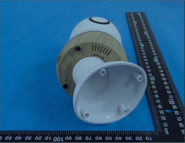
MNJ-MO180TX
Mar 29, 2023Smart Baby Monitor
Equipment Class
DTS - Digital Transmission System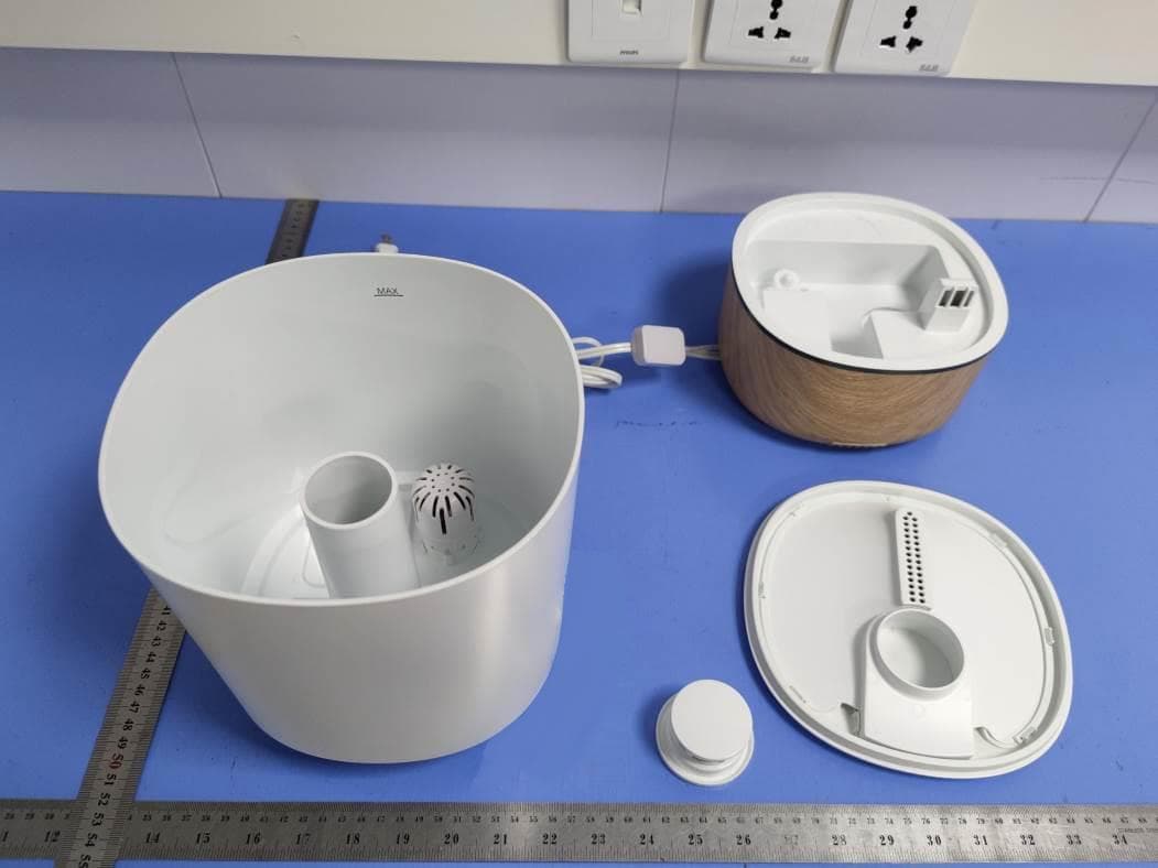
MNJ-IH555
Aug 11, 2021Humidifier
Equipment Class
DTS - Digital Transmission System
MNJ-MO173TX
Jun 06, 2021Baby Monitor
Equipment Class
DTS - Digital Transmission System