MNJ49236RLow Power VHF transmitterP
Dorel Juvenile Group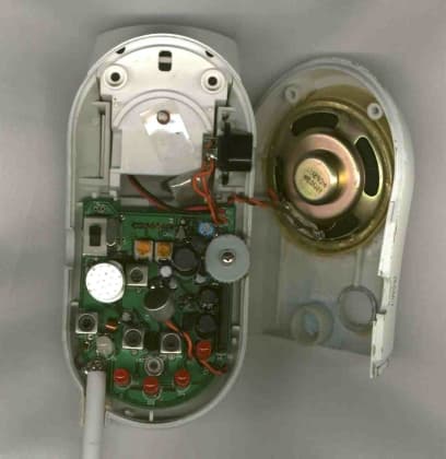
Click to zoom
Application Details
- Equipment Class
- DXT - Part 15 Low Power Transceiver, Rx Verified
- Date of Grant
- May 24, 1999
- Application Purpose
- Original Equipment
- Date of Application
- Apr 07, 1999
- Equipment Note
- Low Power VHF transmitterP
- Frequency Range
- 49.85000000 - 49.87000000
- Company
- Dorel Juvenile Group
- Country
- United States
Documents & Files
Document Text
Text extracted from the exhibit documents filed with the FCC. Open a document above to read the original.
Users Manual
1 Two -Way Intercom Monitor Owner’s Guide Thank you for purchasing the Safety 1st Two-Way Intercom Monitor. This state- of-the-art monitor features a convenient intercom mode that allows two way communication between the parent's unit and baby's unit. Now you can soothe baby with your voice and/or communicate directly to your spouse while in the nursery or kitchen. We are confident you will find this monitor to be an essential part of your baby's nursery. The Baby's Unit has continuous transmission that clearly sends your baby's sounds to the Parent's Unit. The Parent's Unit easily stands on a table or can be clipped to your belt or clothing. Now you can monitor your baby while doing your normal household activities. Both units are completely battery or AC powered. We are sure you will find the Two-Way Intercom Monitor convenient and easy to use. To insure you benefit from all of the great features this monitor offers, and to make sure you use this equipment properly, we urge you to: PLEASE READ ALL INSTRUCTIONS CAREFULLY BEFORE USING THE NURSERY MONITOR KEEP THESE INSTRUCTIONS FOR YOUR FUTURE REFERENCE IF YOU HAVE ANY QUESTIONS, CALL OUR TOLL FREE CONSUMER RELATIONS NUMBER: (800) 723-3065 IN CANADA, PLEASE CALL (800) 721-8933 CAUTION: •THE TWO -WAY INTERCOM NURSERY MONITOR IS NOT INTENDED TO REPLACE RESPONSIBLE AND PROPER PARENTAL SUPERVISION. •YOU SHOULD CHECK YOUR CHILD’S ACTIVITY AT REGULAR INTERVALS AS THIS MONITOR WILL NOT ALERT PARENTS TO THE SILENT ACTIVITIES OF A CHILD. No. 49236 CAUTION RISK OF ELECTRIC SHOCK DO NOT OPEN! CAUTION: TO REDUCE THE RISK OF ELECTRICAL SHOCK, DO NOT REMOVE COVER OR BACK. NO SERVICEABLE PARTS INSIDE. REFER TO SAFETY 1 st CONSUMER RELATIONS:(800) 723-3065. W ARNING:TO REDUCE THE RISK OF FIRE OR ELECTRICAL SHOCK, DO NOT EXPOSE THIS PRODUCT TO W ATER OR MOISTURE. Safety Instruc tions READ INSTRUCTIONS:All the safety instructions should be read before the Nursery Monitor is operated. RETAIN INSTRUCTIONS:The safety instructions should be retained for future reference. HEED WARNINGS:All warnings on the Nursery Monitor and operating instructions should be adhered to. FOLLOW INSTRUCTIONS:All operating instructions should be followed. W ATER AND MOISTURE:The Nursery Monitor should not be used near water, for example, near a bath tub, wash bowl, kitchen sink, laundry tub, in a wet basement, near a swimming pool, etc. VENTILATION:The Nursery Monitor should be placed so that its location or position does not interfere with proper ventilation for the unit. For example, it should never be situated on a bed, sofa, rug or similar surface that may block ventilation. HEAT:The Nursery Monitor should be kept away from heat sources such as radiators, heat registers, stoves or other appliances that produce heat. Introduc tion 2 Features and Co m ponents Parent’s U nit (R ec eiv er) Channel Switch Power/Volume Dial AC Adapter Jack Talk Button Power On/Low Battery Indicator Sound Light LEDs Speaker Flexible Antenna Plastic Belt Clip Battery Compartment (9-volt) Microphone Contents Parent's Unit (Receiver) Baby's Unit (Transmitter) (2) AC Adapters (2) 9-volt batteries (not included) AC POWER SOURCE:The Nursery Monitor should be connected only to the AC Adapters supplied with the unit. POWER CORD PROTECTION:The power supply cord should be routed so that it is not likely to be walked on or pinched by items placed upon or against it. Pay particular attention to the cord at the plug, convenience receptacle, and at the point it exits from the AC adapters. CLEANING:Use a dry cotton cloth to keep the Nursery Monitor free from dust. Do Not Use Water! NON-USE PERIODS:The power cord of the Nursery Monitor should be unplugged from the outlet when unused for long periods of time. The batteries should also be removed during these periods. OBJECT AND LIQUID ENTRY:Care should be taken so that objects do not fall onto the product, and liquids are not spilled into the enclosure through the openings. DAMAGE REQUIRING SERVICE:The Nursery Monitor should be serviced by qualified personnel when: A: The power supply cord or plug has been damaged; B: Objects have fallen or liquid has been spilled onto the product; C: The Monitor has been exposed to rain; D: The Monitor does not appear to operate normally or exhibits a marked change in its performance; E: The Monitor has been dropped or the enclosure damaged. THE USER SHOULD NOT ATTEMPT TO SERVICE OR REPAIR THE MONITOR.ALL SERVICING SHOULD BE REFERRED TO SAFETY 1 st CONSUMER RELATIONS:(800) 723-3065. IN CANADA,PLEASE CALL (800) 721-8933 KEEP ALL PA RTS OF THIS MONITOR OUT OF REACH OF CHILDREN! DO NOT MOUNT IN OR ON CRIB! CAUTION: THE CLEAR CONNECTION RECHARGEABLE NURSERY MONITOR IS NOT INTENDED TO REPLACE PROPER ADULT SUPERVISION. YOU SHOULD CHECK YOUR CHILD’S ACTIVITY AT REGULAR INTERVALS AS THIS MONITOR WILL NOT ALERT PARENTS TO THE SILENT ACTIVITIES OF A CHILD. Batteries Required 1 2 3 4 5 6 7 8 9 10 11 8 11 7 5 1 4 2 3 6 9 10 3 Follow these instructions to operate your Two-Way Intercom Monitor. Reference the illustrations provided on page 3 for the location of all features described in these instructions. Baby’s Unit: For best results, place the Baby's Unit on a table near the crib or bed. It should be facing the baby’s head as close to the crib as possible, but out of baby’s reach. STEP 1Remove the battery cover door by pushing downward in the direction of the arrow. STEP 2Insert a 9-volt battery into the battery compartment by snapping the battery contacts into the corresponding connectors on the battery clip in the unit. Note:The low battery indicator illuminates when the batteries need to be replaced. STEP 3Replace the battery cover door by sliding in place. STEP 4Plug the adapter into an electrical outlet, then plug the round end of the adapter into the Baby's Unit. STEP 5Set the Baby's unit to setting "A". If you experience static or noise interference, switch both units to setting "B". STEP 6Turn the Unit on using the Volume/OFF rotary swi…
Text truncated - open the document above for the full version.
External Photos
Page 1 of 3 FCC ID: MNJ49236R External Photographs External Front
ID Label/Location Info
Page 1 of 1 FCC ID: MNJ49236R FCC Label FCC ID Label 1.6875 x 0.50” Permanently Engraved on Rear of EUT Location of Label on EUT Rear of the EUT FCC ID: MNJ49236R © 1998 Safety 1st All Rights Reserved Made in China THIS DEVICE COMPLIES WITH PART 15 OF THE FCC RULES. OPER- ATIONIS SUBJECT TO THE FOLLOWING TWO CONDITIONS: (1) THIS DEVICE MAY NOT CAUSE HARMFUL INTERFERENCE, AND (2) THIS DEVICE MUST ACCEPT ANY INTERFERENCE RECEIVED, INCLUDING INTERFERENCE THAT MAY CAUSE UNDESIRED OPERATION. CANADA: 210 © 1998 Safety 1st Tous les droits sont réservés. Fabriqué en Chine. CET APPAREIL EST CONFORME À LA PARTIE 15 DU RÈGLEMENT DE LA FCC. LE FONCTIONNEMENT EST SUJET AUX DEUX CON- DITIONS SUIVANTES: (1) CET APPAREIL NE PEUT CAUSER D'INTERFÉRENCES NUISIBLES ET (2) CET APPAREIL REÇOIT TOUTE INTERFÉRENCEMÊME LES INTERFÉRENCES QUI PEU- VENT OCCASIONER UN MAUVAISFONCTIONNEMENT. FCC Label
Internal Photos
Page 1 of 3 FCC ID: MNJ49236R Internal Photo Partially Assembled Page 2 of 3 FCC ID: MNJ49236R Internal PCB Component Side Internal PCB Foil Side Page 3 of 3 Transformer
Operational Description
Page 1 of 1 FCC ID: MNJ49236T & MNJ49236R Product Description Safety 1 st Model 49236 Circuit Description: The Safety 1 st Model 49236 is Nursery Monitor operating in the 49.82 to 49.90 MHz per FCC section 15.235. It consists of a Child unit and a Parent unit. Each is powered by an external AC/DC power adapter or by an internal alkaline battery. This Nursery monitor operation is similar to most monitors sold in the market today. The Child unit will pick up the audio within a room and transmit the signal via FM modulation on a radio carrier. The Parent unit will receive and demodulated FM signal and amplify the audio through an internal speaker. The two devices will be sold as a pair. There is a special two-way mode of operation. When the Parent unit’s Push-to-Talk button is depressed, the Parent unit goes from receive mode to transmit mode. The Child unit checks if the Parent unit is in transmit mode by polling its receiver every two seconds. If there is a signal present from the Parent Unit, the Child unit goes from transmit to receive mode. When the Push-to-Talk button is depressed on the Parent unit, system operation reverts back to normal operation. The Child unit transmits on one of two frequencies, 49.830 and 49.845 respectively. The Parent Unit is usually in receive mode unless the Push-to-Talk button is depressed and then only transmits on one of two frequencies, 49.875 and 49.890 respectively. The receivers in both Parent and Child units are FM super-heterodyne dual conversion. The transmitters are crystal controlled direct FM oscillators. A five kilohertz super-audible tone is generated and detected on both units and modulated on the FM carrier as a means of signal coding to ensure proper signal connection. The case is non-conductive plastic.
Test Report
Low Power VHF Transmitter Radiometrics Midwest Corporation Test Document RP-3974R Issue Date: April 12, 1999 This report concerns: Original grant Equipment type: Low Power Transmitter Transition Rules per 15.37 are not requested. Tests Performed ForTest Facility Safety 1st, Inc. 210 Boylston St. Chestnut Hill, Massachusetts 02167 Radiometrics Midwest Corporation 12 East Devonwood Romeoville, IL 60446 Phone: (815) 293-0772 FAX: (815) 293-0820 [email protected] Test Report Written ByTest Report Approved By Joseph Strzelecki Senior EMC Engineer NARTE EMC-000877-NE Chris W. Carlson Director of Engineering NARTE EMC-000921-NE MEASUREMENT/TECHNICAL REPORT Safety 1st, Inc. Model 49236 FCC ID: MNJ49236R APPLICATION FOR CERTIFICATION RF Emission Measurements Performed For Determination of Compliance with the US Code of Federal Regulations Title 47, Chapter I, FCC Part 15 Subpart B As Required for Certification for Unintentional Radiators Tests Performed ForFCC IDRadiometrics Test DocumentPage Safety 1st, Inc. MNJ49236RRP-3974R2 of 10 Table of Contents 1.0 General Information ..................................................................................................................3 1.1 Product Description ...............................................................................................................3 1.2 Related Submittals ................................................................................................................3 1.3 Tested System Details...........................................................................................................3 1.4 Test Methodology ..................................................................................................................3 1.5 Test Facility............................................................................................................................3 1.6 Test Equipment .....................................................................................................................4 2.0 System Test Configuration........................................................................................................4 2.1 Test System and Justification ................................................................................................4 2.2 EUT Test Configuration ............................................................................................................4 2.3 Special Accessories...............................................................................................................4 2.4 Equipment Modifications........................................................................................................4 Figure 2.1 Configuration of Tested System .................................................................................5 3.0 Occupied Bandwidth Data ........................................................................................................6 Figure 3.1 Occupied Bandwidth Plot ...........................................................................................7 Figure 3.2 Occupied Bandwidth Plot ...........................................................................................8 4.0 Radiated Emissions Data..........................................................................................................9 4.1 Field Strength Calculation....................................................................................................10 5.0 Conducted Emission Data ......................................................................................................10 Notice: This report must not be reproduced (except in full) without the written approval of Radiometrics Midwest Corporation. Tests Performed ForFCC IDRadiometrics Test DocumentPage Safety 1st, Inc. MNJ49236RRP-3974R3 of 10 1.0 General Information 1.1 Product Description The Model 49236T (referred to as the EUT in this report) is a Low Power VHF Transceiver. The EUT is manufactured by Safety 1st, Inc. 1.2 Related Submittals The associated transceiver is operated under part 15. It is subject to the FCC requirements pursuant to the Certification equipment authorization under Part 15 Subpart B, and will be submitted as FCC ID: MNJ49236T. 1.3 Tested System Details The FCC ID's for all equipment, plus descriptions of all cables used in the tested system which have grants, are: Model Number Serial NumberFCC ID Manufacturer & Description Cable Descriptions M/N: 49236 (EUT)MNJ49236RSafety 1st, Inc. Low Power VHF Transmitter Power (1.8m, US) from transformer to EUT Note: SH = Shielded; US = Unshielded; m = Cable Length in Meters, 1.4 Test Methodology The test procedures used are in accordance with the ANSI document C63.4-1992, (July 17, 1992) "Methods of Measurement of Radio Noise Emissions from Low-Voltage Electrical and Electronic Equipment in the Range of 9 kHz to 40 GHz". The specific procedures are described herein. Radiated testing was performed at an antenna to EUT distance of 3 meters. The antenna was raised and lowered from 1 to 4 meters. 1.5 Test Facility The open area test site used to collect the radiated data is located on 8625 Helmar Road in Newark, Illinois. The open field test site has a metal ground screen. Details of the site characteristics are on file with the FCC. Conducted emission measurements and preliminary radiated emission scans were performed in shielded enclosure “A” at Radiometrics' Romeoville, Illinois EMI test lab. These sites have been fully described in a report and accepted by the FCC in a letter dated October 1, 1996 (31040/SIT 1300F2). Conducted emission measurements were performed using a Line Impedance Stabilization Network (LISN) as the pick-up device. This device is constructed in accordance with the circuit diagram provided in Figure 3 of ANSI document C63.4-1992. Tests Performed ForFCC IDRadiometrics Test DocumentPage Safety 1st, Inc. MNJ49236RRP-3974R4 of 10 1.6 Test Equipment Radiated emission measuremen…
Text truncated - open the document above for the full version.
Test Setup Photos
Page 1 of 2 FCC ID: MNJ49236R Test setup Photographs Conducted Emissions Page 2 of 2 Radiated Emissions
Contact Information
Applicant
Dan Desimone(Director R & A, Project Management)
Technical Contact
Radiometrics Midwest CorporationJoseph R Strzelecki
[email protected]815-293-0772
Romeoville, Illinois · United States
Non-Technical Contact
Radiometrics Midwest CorporationJoan E Strzelecki
[email protected]815-293-0772
Technical Specifications
| # | Rule Parts | Frequency Range | Power Output |
|---|---|---|---|
| 1 | 15C | 49.85 MHz - 49.87 MHz | - |
Other Applications from Dorel Juvenile Group
MNJ-MO191
Apr 09, 2024CryAssist Audio Monitor
Equipment Class
DSS - Part 15 Spread Spectrum Transmitter
MNJ-MO183TX
Dec 05, 2023See Pro 360 Baby Monitor
Equipment Class
NII - Unlicensed National Information Infrastructure TX
MNJ-MO180TX
Mar 29, 2023Smart Baby Monitor
Equipment Class
DTS - Digital Transmission System
MNJ-IH555
Aug 11, 2021Humidifier
Equipment Class
DTS - Digital Transmission System
MNJ-MO173TX
Jun 06, 2021Baby Monitor
Equipment Class
DTS - Digital Transmission System