MNL160020021025Wireless Mouse
Adomax Technology Co Ltd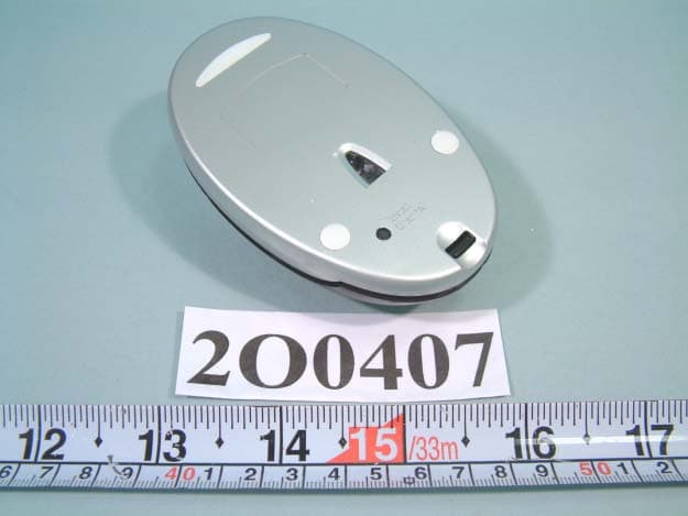
Click to zoom
Application Details
- Equipment Class
- DXX - Part 15 Low Power Communication Device Transmitter
- Date of Grant
- Mar 05, 2003
- Application Purpose
- Original Equipment
- Date of Application
- Mar 05, 2003
- Equipment Note
- Wireless Mouse
- Frequency Range
- 27.04000000 - 27.05000000
- Company
- Adomax Technology Co Ltd
- Country
- Taiwan
Documents & Files
Document Text
Text extracted from the exhibit documents filed with the FCC. Open a document above to read the original.
Users Manual
FCC ID: MNL160020021025 AM 1600 Manual The Federal Communication Commission Statement This equipment has been tested and found to comply with the limits for a Class B digital device, pursuant to Part 15 of the FCC Rules. These limits are designed to provide reasonable protection. This equipment generates, uses and can radiate radio frequency energy and, if not installed and used in accordance with the instruction, may cause harmful interference to radio communication. However, there is no guarantee that interference will not occur in a particular installation. If this equipment does cause harmful interference to radio or television reception, which can be determined by turning the equipment off and on, the user is encouraged to try to correct the interference by one or more of the following measures: z Reorient or relocate the receiving antenna. z Increase the separation between the equipment and receiver. z Connect the equipment into an outlet on a circuit different from that to which the receiver is connected. z Consult the dealer or an experienced radio/ TV technician for help. Changes or modifications not expressly approved by the party responsible for compliance could void the user‘s authority to operate the equipment. Use only shielded cables to connect I/O devices to this equipment. You are cautioned that change or modifications not expressly approved by the party responsible for complies could void your authority to operate the equipment. THIS DEVICE COMPLIES WITH PART 15 OF FCC RULES. OPERATION IS SUBJECT TO THE FOLLOWING TWO CONDITION: (1) This device may not cause harmful interference and (2) This device must accept any interference received, including interference that may cause undesired operation. Welcomed! Thank you for purchasing this RF Wireless Optical Mouse. Utilizing the latest wireless RF technology, this mouse can work from any directions or angles even when objects hinder between your mouse & the receiver. You can locate the device freely and enjoy its convenience. Install Your Wireless Mouse Hardware Installation Installing Batteries 1. Remove the battery cover from the bottom of your mouse. (1)Press down the lid on the bottom of the mouse (2)The top shell pops out automatically. Push forward the top shell. 2. Insert two AA Alkaline Batteries into the battery compartment. 3. Replace the cover carefully. z Once the battery is placed correctly in the mouse, the optical LED located at the mouse bottom will light up. Connect the Mouse To connect to a USB port (Windows 98 or higher required), connect the USB receiver to the USB port on the computer. To connect to a PS/2 port, TURN OFF your computer before installation. 1. Connect the PS/2 adapter to the USB receiver. 2. Insert the receiver into the PS/2 port on the computer. 3. Turn on your computer. If you work under Windows environment, you may be prompted to insert the Windows software CD. Please insert this CD into the computer’s CD-ROM when you are asked to do so and follow the on-screen instructions. Establishing a Communication Link First of all, please find out if you bought a 400 cpi or 800 cpi mouse. (Please refer to the label on the box.) For 400 cpi mouse 1. After you insert the receiver to your computer, the receiver will not light up or blink; 2. Please press the reset button on the back of your mouse in 3 minutes; reset button 3. When the receiver link with the mouse successfully, the LED of the receiver will blink. For 800 cpi mouse 1. After you insert the receiver to your computer, the LED of the receiver will flash slowly; 2. Press the reset button on the back of your mouse in 3 minutes; reset button 3. Once the receiver link with the mouse successfully, the LED of the receiver will blink quickly. If the reset button was not pressed within 3 minutes after the receiver is connected, please relocate the receiver and press the reset button again within 3 minutes. Software Installation (Optional) This mouse is totally compatible with Windows 98/ 2000/ ME/ XP without driver installation. When driver supports, this mouse will be able to work under Windows 95. Additional functions will also be available for the middle wheel. 1. Click Start and uninstall your previous mouse program. 2. Insert software diskette into drive A or B. 3. Click Start on the Taskbar and select “Run.” 4. From the Run dialogue box, select (or type) A:\SETUP and press ENTER. 5. From the Select Device Type dialogue box, choose USB Port or PS/2 Port and then click NEXT. To access the software, double-click the white mouse icon on the Taskbar to display the Mouse Properties tabs. Software Functions 1. Wheel Mode: z System (Intelli-Mouse) Mode. z Enhanced Scroll Mode. P.S. Please click “Help” for further information. 2. Scroll Speed: z Scroll 1 to 10 lines per scrolling unit. z Scroll one page per scrolling unit. 3. Universal Scroll: Control the directions and speed of scrolling bar by moving your mouse. You can set up the vertical or horizontal scrolling directions and speed. 4. Universal Zoom: Magnify or minimize any characters or illustrations. You can adjust the zoomed area or zoom factor by pushing the wheel forward or backward. 5. Auto Scroll: Move the mouse once in the direction you want to scroll. 6. Horizontal Wheel: You can press the wheel button to change the scroll direction from vertical to horizontal. Just exchange the scroll directions by clicking the wheel button once. It’s specially designed for long documents reading. 7. Others: There are 38 kinds of other functions for the middle wheel assignment. Important Note z To optimize the performace of your RF reception, please make your receiver at least 8 inches (20 cm) away from electronical devices, such as monitor, speakers or external storage devices. z Please avoid your RF optical mouse to work on a metal surface. Metals such as iron, aluminum or copper shield the radio frequency transmission and may slow down the response of the mouse or cause the mouse to fail temporarily…
Text truncated - open the document above for the full version.
Block Diagram
FCC ID: MNL160020021025
External Photos
FCC ID : MNL160020021025 NUMBER 1 FRONT SIDE OF EUT FCC ID : MNL160020021025 NUMBER 2 REAR SIDE OF EUT
ID Label/Location Info
FCC ID: MNL160020021025 FCC ID LOCATION
ID Label/Location Info
FCC ID: MNL160020021025
Internal Photos
FCC ID : MNL160020021025 Number 1 Mechanical Construction FCC ID : MNL160020021025 Number 2 Mechanical Construction FCC ID : MNL160020021025 Number 3 Mechanical Construction FCC ID : MNL160020021025 Number 4 Front side of Main Board FCC ID : MNL160020021025 Number 5 REAR side of Main Board
Operational Description
FCC ID : MNL160020021025 Mouse: 1.When the mouse were moved, the IRPD would detect the glide signal to also transmit signal to the MCU. 2.The MCU will convert the signal and modulate the signal. (Use FSK mode) 3.Through the 27MHZ frequency transmit the modulation signal. Receiver: 1.When the receiver receives the modulation signal will demodulate signal through RF circuit. And responds signal to MCU. 2.The MCU meeting converts the signal PC acceptable format.
Schematics
FCC ID: MNL160020021025 FCC ID: MNL160020021025
Test Report
FCC TEST REPORT Report No. : F2O0407-02 SPORTON International Inc. TEL : 886-2-2696-2468 FAX : 886-2-2696-2255 FCC TEST REPORT for 47 CFR, Part 15, Subpart C Equipment : WIRELESS MOUSE Model No. : AM-1600U / AM-1600UP FCC ID : MNL160020021025 Filing Type : Certification Applicant : ADOMAX TECHNOLOGY CO., LTD 5F/2, No. 192, Chung Hsin Road, Sec. 2, Hsin Tien City, 231, Taipei Hsien, Taiwan. The test result refers exclusively to the test presented test model / sample. Without written approval of SPORTON International Inc., the test report shall not be reproduced except in full. Certificate or Test Report must not be used by the applicant to claim the product in this test report endorsement by NVLAP or any agency of U.S. government. SPORTON International Inc. 6F, No.106, Sec. 1, Hsin Tai Wu Rd., Hsi Chih, Taipei Hsien, Taiwan, R.O.C. FCC TEST REPORT Report No. : F2O0407-02 SPORTON International Inc. FCC ID : MNL160020021025 TEL : 886-2-2696-2468 Page No. : i FAX : 886-2-2696-2255 Issued Date : Feb. 12, 2003 Table of Contents History of this test report....................................................................................................................................ii CERTIFICATE OF COMPLIANCE........................................................................................................................1 1. General Description of Equipment under Test.............................................................................................2 1.1. Applicant..........................................................................................................................................................................................2 1.2. Manufacturer ...................................................................................................................................................................................2 1.3. Basic Description of Equipment under Test ....................................................................................................................................2 1.4. Feature of Equipment under Test ...................................................................................................................................................2 2. Test Configuration of Equipment under Test ...............................................................................................3 2.1. Test Manner ....................................................................................................................................................................................3 2.2. Description of Test System .............................................................................................................................................................3 2.3. Connection Diagram of Test System ..............................................................................................................................................5 3. General Information of Test............................................................................................................................8 3.1. Test Facility .....................................................................................................................................................................................8 3.2. Standard for Methods of Measurement...........................................................................................................................................8 3.3. Test in Compliance with ..................................................................................................................................................................8 3.4. Frequency Range Investigated .......................................................................................................................................................8 3.5. Test Distance ..................................................................................................................................................................................8 4. Test of Conducted Powerline .........................................................................................................................9 5. Test of Radiated Emission............................................................................................................................10 5.1. Major Measuring Instruments........................................................................................................................................................10 5.2. Test Procedures ............................................................................................................................................................................11 5.3. Typical Test Setup Layout of Radiated Emission..........................................................................................................................12 5.4. Test Result of Radiated Emission .................................................................................................................................................13 6. EMI Suppression Component List ...............................................................................................................14 7. Antenna Factor & Cable Loss ......................................................................................................................15 8. List of Measuring Equipments Used ...........................................................................................................16 9. Uncertainty of Test Site ................................................................................................................................17 FCC TEST REPORT Report No. : F2O0407-02 SPORTON International Inc. FCC ID : MNL160020021025 TEL : 886-2-2696-2468 Page No. : ii FAX : 886-2-2696-2255 Issued Date : Feb. 12, 2003 History of this test report Original Report Issue Date: Oct. 31, 2…
Text truncated - open the document above for the full version.
Test Setup Photos
FCC TEST REPORT Report No. : F2O0407-02 SPORTON International Inc. FCC ID : MNL160020021025 TEL : 886-2-2696-2468 Page No. : 1 of 1 FAX : 886-2-2696-2255 Issued Date : Feb. 12, 2003 1.1. Photographs of Radiated Emission Test Configuration The photographs show the configuration that generates the maximum emission. FRONT VIEW REAR VIEW
Contact Information
Applicant
Tony Yang(Engineer)
Test Firm
SPORTON International IncKathy Lin
Technical Specifications
| # | Rule Parts | Frequency Range | Power Output |
|---|---|---|---|
| 1 | 15C | 27.04 MHz - 27.05 MHz | - |
Other Applications from Adomax Technology Co Ltd
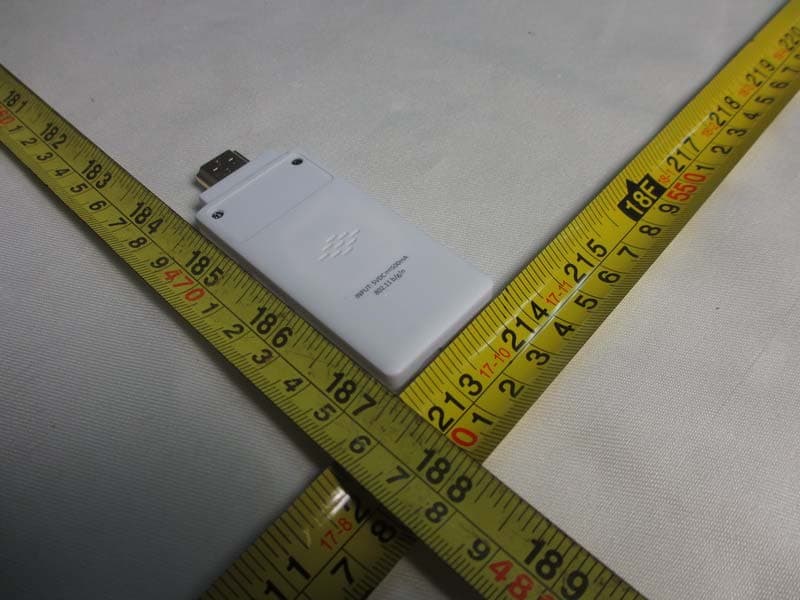
MNLAX-16
Sep 29, 2013WiFi Display Dongle
Equipment Class
DTS - Digital Transmission System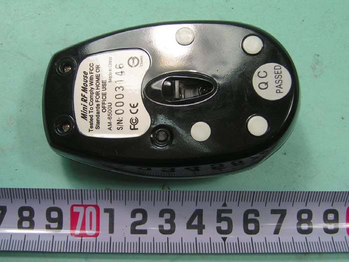
MNLAM6500UP
Sep 27, 2005Cordless Portable Mini Optical Mouse
Equipment Class
DXX - Part 15 Low Power Communication Device Transmitter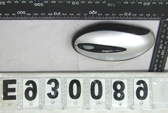
MNL220020040226
Mar 11, 2004RF OPTICAL MOUSE
Equipment Class
DXX - Part 15 Low Power Communication Device Transmitter
MNLAM160020021025
Jan 26, 2003Wireless Mouse
Equipment Class
DXX - Part 15 Low Power Communication Device Transmitter
MNL98929110077
Jan 19, 2003Wireless Mouse
Equipment Class
DXX - Part 15 Low Power Communication Device Transmitter