MQ4BHC110Bluetooth Headset
Abocom Systems Inc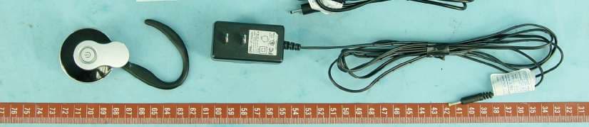
Click to zoom
Application Details
- Equipment Class
- DSS - Part 15 Spread Spectrum Transmitter
- Date of Grant
- Aug 03, 2006
- Application Purpose
- Original Equipment
- Date of Application
- Aug 03, 2006
- Equipment Note
- Bluetooth Headset
- Frequency Range
- 2402.00000000 - 2480.00000000
- Company
- Abocom Systems Inc
- Country
- Taiwan
Documents & Files
Document Text
Text extracted from the exhibit documents filed with the FCC. Open a document above to read the original.
Users Manual
BHC110 -- Bluetooth Headset Quick Installation Guide Buttons Starting to Use How to Charge Plug the charger into the headset. Plug the other end of the charger into an electrical outlet. During the charging, the red LED turns on and remains on until charging is complete. When charging is complete (red LED is off), remove the charger form the electrical outlet and detach the charger from the speaker. Pairing Your Headset and Phone Before you can use your Bluetooth headset you’re your phone it has to be added once to the phone. Follow the instruction form the phone user guide on how to turn on the Bluetooth in your phone. With the headset and phone in close proximity: 1. Make sure the headset is in power off. Press the power button for 6 seconds until the blue and red LED flashes. 2. Initiate the pairing sequence using hands-free mode if available. The unit may also be paired in headset mode if hands-free mode is not available. 3. Perform a device discovery from the phone. For details on device discovery for your phone, refer to the user guide for the phone . 4. Select the Mono Headset from the discovered devices list, and then confirm following the on screen prompts. 5. When prompted by the phone, enter the passkey 0000 , and then confirm to pair the headset with the phone. Controlling Headset Volume Increase: Press the volume button in the + position repeatedly until you reach the desired volume level. Decrease: Press the volume button in the - position repeatedly until you reach the desired volume level. Placing and Receiving Calls Y our headset supports both Hands-free and Headset Profiles. Accessing call functions depends on which profile your phone supports. Action Function Very Long Press Power Pairing Power On Power Off Long Press Power Reject a Call Receive a Call End a Call Short Press Power Voice Dial Redial Long Press Redial Call Transfer Mute On Short Press Redial Mute Off Using Your Headset Indicators LED Headset OFF Power Off Red/Blue rapid flashes Pairing mode Blue flashes Power On Red On Charging Red flashes Power Low Red flashed 5 times Powering Off Troubleshooting Q: No connection to phone A: Make sure the headset is charged and within range of the phone. Check or redo the Bluetooth setting in the phone. Q: The headset is automatically switched off A: The battery is too low. The indicator light on the headset flashes red. Q: Unexpected behavior A: Recharge the headset. The headset will reset when recharging the headset Q: Battery capacity A: A battery that has been infrequently used or a new one could have reduced capacity. It may need to be fully recharged and discharged a number of times. Federal Communication Commission Interference Statement This equipment has been tested and found to comply with the limits for a Class B digital device, pursuant to Part 15 of the FCC Rules. These limits are designed to provide reasonable protection against harmful interference in a residential installation. This equipment generates, uses and can radiate radio frequency energy and, if not installed and used in accordance with the instructions, may cause harmful interference to radio communications. However, there is no guarantee that interference will not occur in a particular installation. If this equipment does cause harmful interference to radio or television reception, which can be determined by turning the equipment off and on, the user is encouraged to try to correct the interference by one of the following measures: - Reorient or relocate the receiving antenna. - Increase the separation between the equipment and receiver. - Connect the equipment into an outlet on a circuit different from that to which the receiver is connected. - Consult the dealer or an experienced radio/TV technician for help. This device complies with Part 15 of the FCC Rules. Operation is subject to the following two conditions: (1) This device may not cause harmful interference, and (2) this device must accept any interference received, including interference that may cause undesired operation. FCC Caution: Any changes or modifications not expressly approved by the party responsible for compliance could void the user's authority to operate this equipment. IMPORTANT NOTE: FCC Radiation Exposure Statement: This equipment complies with FCC radiation exposure limits set forth for an uncontrolled environment. End users must follow the specific operating instructions for satisfying RF exposure compliance. This transmitter must not be co-located or operating in conjunction with any other antenna or transmitter.
External Photos
Page 1 CONSTRUCTION PHOTOS OF EUT Page 2 Page 3
ID Label/Location Info
Label location_BHC110 (820x615x16M jpeg)
ID Label/Location Info
Bluetooth Headset Model name : BHC110 FCC ID : MQ4BHC110
Internal Photos
Page 4 Page 5 Page 6
Operational Description
FCC ID: MQ4BHC110 Report No. RF 950419L03 Operational Description The transmitter of the EUT (Bluetooth Headset) is powered by 3.7Vdc from battery. The antenna is printed antenna without antenna connector. This device is a Frequency Hopping device with 79 hopping frequencies. For more detailed instruction, please take a look at the user’s manual.
RF Exposure Info
FCC ID: MQ4BHC110 Report No: SA950419L03 1 RF EXPOSURE REPORT REPORT NO.: SA950419L03 MODEL NO.: BHC110 ACCORDING: FCC Guidelines for Human Exposure IEEE C95.1 APPLICANT: AboCom Systems, Inc. ADDRESS: 1F,No.21,Yanfa 2nd Rd.,SBIP,Hsinchu City 300,Taiwan(R.O.C) ISSUED BY: Advance Data Technology Corporation LAB ADDRESS: No. 47, 14th Ling, Chia Pau Tsuen, Lin Kou Hsiang 244, Taipei Hsien, Taiwan, R.O.C. TEST LOCATION: No. 19, Hwa Ya 2 nd Rd., Wen Hwa Tsuen, Kwei Shan Hsiang, Taoyuan Hsien 333, Taiwan, R.O.C. FCC ID: MQ4BHC110 Report No: SA950419L03 2 RF Exposure Measurement 1. Introduction In this document, we try to prove the safety of radiation harmfulness to the human body for our product. The limit for Maximum Permissible Exposure (MPE) specified in FCC 1.1310 is followed. The Gain of the antenna used in this product is measured in a Fully Anechoic Chamber (FAC) calibrated for antenna measurement in ADT, and also the maximum total power input to the antenna is measured. Through the Friis transmission formula and the maximum gain of the antenna, we can calculate the distance, away from the product, where the limit of MPE is reached. Although the Friis transmission formula is a far field assumption, the calculated result of that is an over-prediction for near field power density. We will take that as the worst case to specify the safety range. 2. RF Exposure Limit According to FCC 1.1310: The criteria listed in the following table shall be used to evaluate the environmental impact of human exposure to radio-frequency (RF) radiation as specified in 1.1307(b) LIMITS FOR MAXIMUM PERMISSIBLE EXPOSURE (MPE) Frequency Range (MHz) Electric Field Strength (V/m) Magnetic Field Strength (A/m) Power Density (mW/cm 2 ) Average Time (minutes) (A)Limits For Occupational / Control Exposures 300-1500......F/3006 1500-100,000......56 (B)Limits For General Population / Uncontrolled Exposure 300-1500......F/15006 1500-100,000......1.030 F = Frequency in MHz FCC ID: MQ4BHC110 Report No: SA950419L03 3 3. Friis Formula Friis transmission formula: Pd = (Pout*G) / (4*pi*r 2 ) where Pd = power density in mW/cm 2 Pout = output power to antenna in mW G = gain of antenna in linear scale Pi = 3.1416 R = distance between observation point and center of the radiator in cm If we know the maximum Gain of the antenna and the total power input to the antenna, through the calculation, we will know the MPE value at distance 20cm. Ref.: David K. Cheng, Field and Wave Electromagnetics, Second Edition, Page 640, Eq. (11-133). 4 EUT Operating condition The software provided by Manufacturer enabled the EUT to transmit and receive data at lowest, middle and highest channel individually. FCC ID: MQ4BHC110 Report No: SA950419L03 4 5 Conclusion No Evaluation Required if power is below this threshold: F(GHz)mW Low2.402 High2.480 24.585 Maximum measured transmitter power: Pout (dBm)Pout (mW) Conducted Power1.651.462 EIRP Power1.611.449 *Note: The antenna is Printed antenna with –0.04dBi gain Threshold for no SAR evaluation is 24.585mW Transmitter power is 1.462mW Conclusion: No SAR evaluation required since Transmitter Pout is below FCC threshold
Test Report
Report No.: RF950419L031Report Format Version 2.0.4 FCC TEST REPORT REPORT NO.: RF950419L03 MODEL NO.: BHC110 RECEIVED: May 17, 2006 TESTED: Jul. 21 ~ Jul. 25, 2006 ISSUED: Jul. 28, 2006 APPLICANT:AboCom Systems, Inc. ADDRESS: 1F,No.21,Yanfa 2nd Rd.,SBIP, Hsinchu City 300, Taiwan(R.O.C) ISSUED BY: Advance Data Technology Corporation LAB ADDRESS: No. 47, 14 th Ling, Chia Pau Tsuen, Lin Kou Hsiang 244, Taipei Hsien, Taiwan, R.O.C. TEST LOCATION: No. 19, Hwa Ya 2 nd Rd., Wen Hwa Tsuen, Kwei Shan Hsiang, Taoyuan Hsien 333, Taiwan, R.O.C. This test report consists of 67 pages in total. It may be duplicated completely for legal use with the approval of the applicant. It should not be reproduced except in full, without the written approval of our laboratory. The client should not use it to claim product endorsement by CNLA, A2LA or any government agencies. The test results in the report only apply to the tested sample. NO. 2177-01 Report No.: RF950419L032Report Format Version 2.0.4 TABLE OF CONTENTS 1.CERTIFICATION.......................................................................................................4 2.SUMMARY OF TEST RESULTS...............................................................................5 2.1MEASUREMENT UNCERTAINTY.............................................................................6 3.GENERAL INFORMATION........................................................................................7 3.1 GENERAL DESCRIPTION OF EUT..........................................................................7 3.2 DESCRIPTION OF TEST MODES............................................................................8 3.2.1 CONFIGURATION OF SYSTEM UNDER TEST........................................................9 3.2.2 TEST MODE APPLICABILITY AND TESTED CHANNEL DETAIL............................10 3.2.3 GENERAL DESCRIPTION OF APPLIED STANDARDS..........................................12 3.2.4 DESCRIPTION OF SUPPORT UNITS.....................................................................12 4. TEST TYPES AND RESULTS.................................................................................13 4.1 CONDUCTED EMISSION MEASUREMENT............................................................13 4.2 RADIATED EMISSION MEASUREMENT.................................................................13 4.2.1 LIMITS OF RADIATED EMISSION MEASUREMENT..............................................13 4.2.2 TEST INSTRUMENTS.............................................................................................14 4.2.3 TEST PROCEDURES.............................................................................................15 4.2.4 DEVIATION FROM TEST STANDARD....................................................................15 4.2.5 TEST SETUP..........................................................................................................16 4.2.6 EUT OPERATING CONDITIONS.............................................................................16 4.2.7 TEST RESULTS......................................................................................................17 4.3 NUMBER OF HOPPING FREQUENCY USED.......................................................24 4.3.1 LIMIT OF HOPPING FREQUENCY USED..............................................................24 4.3.2 TEST INSTRUMENTS.............................................................................................24 4.3.3 TEST PROCEDURES.............................................................................................24 4.3.4 DEVIATION FROM TEST STANDARD....................................................................25 4.3.5 TEST SETUP..........................................................................................................25 4.3.6 TEST RESULTS......................................................................................................25 4.4 DWELL TIME ON EACH CHANNEL.......................................................................28 4.4.1 LIMIT OF DWELL TIME USED................................................................................28 4.4.2 TEST INSTRUMENTS.............................................................................................28 4.4.3 TEST PROCEDURES.............................................................................................28 4.4.4 DEVIATION FROM TEST STANDARD....................................................................28 4.4.5 TEST SETUP..........................................................................................................29 4.4.6 TEST RESULTS......................................................................................................29 4.5 CHANNEL BANDWIDTH.........................................................................................37 4.5.1 LIMITS OF CHANNEL BANDWIDTH.......................................................................37 4.5.2 TEST INSTRUMENTS.............................................................................................37 4.5.3 TEST PROCEDURE................................................................................................37 4.5.4 DEVIATION FROM TEST STANDARD....................................................................38 Report No.: RF950419L033Report Format Version 2.0.4 4.5.5 TEST SETUP..........................................................................................................38 4.5.6 EUT OPERATING CONDITION...............................................................................38 4.5.7 TEST RESULTS......................................................................................................38 4.6 HOPPING CHANNEL SEPARATION......................................................................44 4.6.1 LIMIT OF HOPPING CHANNEL SEPARATION.......................................................44 4.6.2 TEST INSTRUMENTS.......................................................................…
Text truncated - open the document above for the full version.
Test Report
Report No.: RF950419L0341Report Format Version 2.0.4 FOR 8DPSK EUT TEST CONDITION MEASUREMENT DETAIL MODULATION TYPE 8DPSK ENVIRONMENTAL CONDITIONS 25deg. C, 65%RH, 991hPa TESTED BY Brad Wu INPUT POWER (SYSTEM) 120Vac, 60 Hz CHANNELCHANNEL FREQUENCY (MHz)20dB BANDWIDTH (MHz) 024021.218 3924411.218 7824801.212 Report No.: RF950419L0342Report Format Version 2.0.4 CH 0 CH 39 Report No.: RF950419L0343Report Format Version 2.0.4 CH 78 Report No.: RF950419L0344Report Format Version 2.0.4 4.6 HOPPING CHANNEL SEPARATION 4.6.1 LIMIT OF HOPPING CHANNEL SEPARATION At least 25kHz or two-third of 20dB hopping channel bandwidth (whichever is greater). 4.6.2 TEST INSTRUMENTS DESCRIPTION & MANUFACTURERMODEL NO.SERIAL NO.CALIBRATED UNTIL SPECTRUM ANALYZERFSEK30100049Aug. 14, 2006 NOTES: The calibration interval of the above test instruments is 12 months. And the calibrations are traceable to NML/ROC and NIST/USA. 4.6.3 TEST PROCEDURES 1.Check the calibration of the measuring instrument using either an internal calibrator or a known signal from an external generator. 2.Turn on the EUT and connect it to measurement instrument. Then set it to any one convenient frequency within its operating range. 3.By using the MaxHold function record the separation of two adjacent channels. 4.Measure the frequency difference of these two adjacent channels by SA MARK function. And then plot the result on SA screen. 5.Repeat above procedures until all frequencies measured were complete. Report No.: RF950419L0345Report Format Version 2.0.4 4.6.4 DEVIATION FROM TEST STANDARD No deviation. 4.6.5 TEST SETUP 4.6.6 TEST RESULTS FOR GFSK EUT TEST CONDITIONMEASUREMENT DETAIL MODULATION TYPE GFSK ENVIRONMENTAL CONDITIONS 25deg. C, 65%RH, 991hPa TESTED BY Brad Wu INPUT POWER (SYSTEM) 120Vac, 60 Hz CHANNEL FREQUENCY (MHz) ADJACENT CHANNEL SEPARATION (MHz) 20dB BANDWIDTH (MHz) MINIMUM LIMIT (MHz) PASS / FAIL 024021.0000.8760.584PASS 3924411.0100.8640.576PASS 7824801.0150.8850.590PASS NOTE: The minimum limit is two-third 20dB bandwidth. Test results please refer to next two pages. EUT SPECTRUM ANALYZER Report No.: RF950419L0346Report Format Version 2.0.4 CH 0 CH 39 Report No.: RF950419L0347Report Format Version 2.0.4 CH 78 Report No.: RF950419L0348Report Format Version 2.0.4 FOR 8DPSK EUT TEST CONDITION MEASUREMENT DETAIL MODULATION TYPE 8DPSK ENVIRONMENTAL CONDITIONS 25deg. C, 65%RH, 991hPa TESTED BY Brad Wu INPUT POWER (SYSTEM) 120Vac, 60 Hz CHANNEL FREQUENCY (MHz) ADJACENT CHANNEL SEPARATION (MHz) 20dB BANDWIDTH (MHz) MINIMUM LIMIT (MHz) PASS / FAIL 024021.0051.2180.812PASS 3924411.0101.2180.812PASS 7824801.0051.2120.808PASS NOTE: The minimum limit is two-third 20dB bandwidth. Test results please refer to next two pages. Report No.: RF950419L0349Report Format Version 2.0.4 CH 0 CH 39 Report No.: RF950419L0350Report Format Version 2.0.4 CH 78 Report No.: RF950419L0351Report Format Version 2.0.4 4.7 MAXIMUM PEAK OUTPUT POWER 4.7.1 LIMITS OF MAXIMUM PEAK OUTPUT POWER MEASUREMENT The Maximum Peak Output Power Measurement is 30dBm. 4.7.2 TEST INSTRUMENTS DESCRIPTION & MANUFACTURERMODEL NO.SERIAL NO.CALIBRATED UNTIL SPECTRUM ANALYEERFSEK30100049Aug. 14, 2006 NOTE: The calibration interval of the above test instruments is 12 months and the calibrations are traceable to NML/ROC and NIST/USA. 4.7.3 TEST PROCEDURES a. Check the calibration of the measuring instrument using either an internal calibrator or a known signal from an external generator. b. Turn on the EUT and connect it to measurement instrument. Then set it to any one convenient frequency within its operating range. Set a reference level on the measuring instrument equal to the highest peak value. c. The center frequency of the spectrum analyzer is set to the fundamental frequency and using 3MHz RBW and 10 MHz VBW. d. Measure the captured power within the band and recording the plot. e. Repeat above procedures until all frequencies required were complete. 4.7.4 DEVIATION FROM TEST STANDARD No deviation Report No.: RF950419L0352Report Format Version 2.0.4 4.7.5 TEST SETUP For the actual test configuration, please refer to the related Item – Photographs of the Test Configuration. 4.7.6 EUT OPERATING CONDITION The software provided by client enabled the EUT to transmit and receive data at lowest, middle and highest channel frequencies individually. 4.7.7 TEST RESULTS FOR GFSK EUT TEST CONDITION MEASUREMENT DETAIL MODULATION TYPE GFSK ENVIRONMENTAL CONDITIONS 25deg. C, 65%RH, 991hPa TESTED BY Brad Wu INPUT POWER (SYSTEM) 120Vac, 60 Hz CHANNEL CHANNEL FREQUENCY (MHz) PEAK POWER OUTPUT (mW) PEAK POWER OUTPUT (dBm) PEAK POWER LIMIT (mW) PASS/FAIL 024021.4621.650125PASS 3924411.1750.700125PASS 7824801.0000.000125PASS EUT SPECTRUM ANALYZER Report No.: RF950419L0353Report Format Version 2.0.4 CH 0 CH 39 Report No.: RF950419L0354Report Format Version 2.0.4 CH 78 Report No.: RF950419L0355Report Format Version 2.0.4 FOR 8DPSK EUT TEST CONDITION MEASUREMENT DETAIL MODULATION TYPE 8DPSK ENVIRONMENTAL CONDITIONS 25deg. C, 65%RH, 991hPa TESTED BY Brad Wu INPUT POWER (SYSTEM) 120Vac, 60 Hz CHANNEL CHANNEL FREQUENCY (MHz) PEAK POWER OUTPUT (mW) PEAK POWER OUTPUT (dBm) PEAK POWER LIMIT (mW) PASS/FAIL 024020.485-3.140125PASS 3924410.499-3.020125PASS 7824800.547-2.620125PASS Report No.: RF950419L0356Report Format Version 2.0.4 CH 0 CH 39 Report No.: RF950419L0357Report Format Version 2.0.5 CH 78 Report No.: RF950419L0358Report Format Version 2.0.5 4.8 BAND EDGES MEASUREMENT 4.8.1 LIMITS OF BAND EDGES MEASUREMENT Below –20dB of the highest emission level of operating band (in 100KHz RBW). 4.8.2 TEST INSTRUMENTS DESCRIPTION & MANUFACTURERMODEL NO.SERIAL NO.CALIBRATED UNTIL SPECTRUM ANALYZERFSEK30100049Aug. 14, 2006 NOTES: The calibration interval of the above test instruments is 12 months. And the calibrations are traceable to NML/ROC and NIST/USA. 4.8.3 TEST PROCEDURE The transmitter output was connected to the spectrum analyzer via a low lose cable. Set both RBW and VBW of spectrum analyzer to 100 kHz …
Text truncated - open the document above for the full version.
Test Setup Photos
1 PHOTOGRAPHS OF THE TEST CONFIGURATION RADIATED EMISSION TEST
Contact Information
Applicant
Harry Huang(Manager)
Technical Contact
Advance Data Technology Corporation (Hwa Ya)Gary Chang
[email protected]886-3-3183232
No. 19, Hwa Ya 2nd Rd., Kwei Shan Hsiang · Taoyuan Hsien · Taiwan
Non-Technical Contact
Advance Data Technology CorporationEllis Wu
[email protected]886-3-3183232
Test Firm
Bureau Veritas CPS (H.K.) Ltd. Taoyuan BranchRichard Chen
Technical Specifications
| # | Rule Parts | Frequency Range | Power Output |
|---|---|---|---|
| 1 | 15C | 2.40 GHz - 2.48 GHz | 1.50 mW |
Other Applications from Abocom Systems Inc

MQ4WM5208
Oct 27, 2015802.11b/g/n Module
Equipment Class
DTS - Digital Transmission System
MQ4AM7221
Mar 18, 20152T2R 802.11b/g/n/ac Module
Equipment Class
DTS - Digital Transmission System
MQ4PLW72
Mar 18, 201511ac WiFi Extender Smart Plug / 11ac WiFi Extender
Equipment Class
NII - Unlicensed National Information Infrastructure TX
MQ4CB1522M
Sep 22, 2014IP Camera
Equipment Class
DTS - Digital Transmission System
MQ4-MBR-1100
Sep 21, 2014Android TV Dongle
Equipment Class
JBC - Part 15 Class B Computing Device/Personal Computer