MQ4BPCMLM5610/100 Fast Ethernet Plus 56k Fax/Modem PCMCI Card
Abocom Systems Inc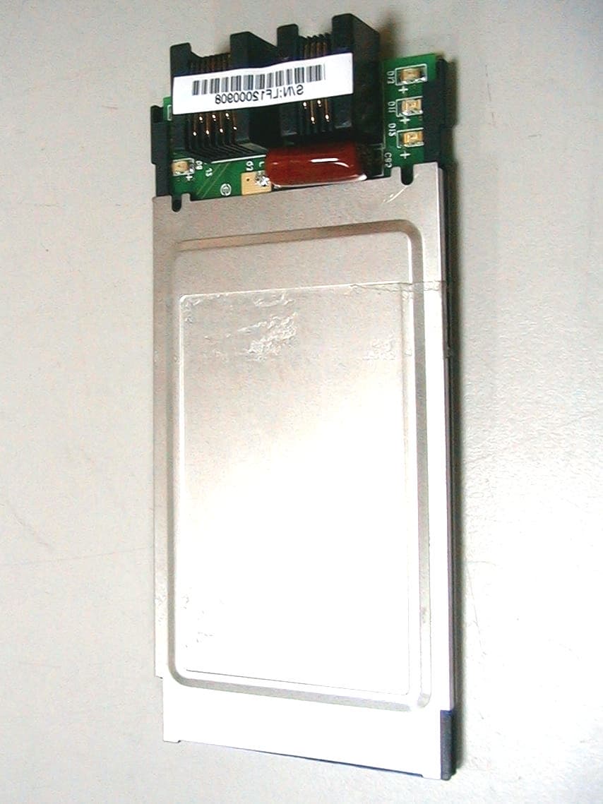
Click to zoom
Application Details
- Equipment Class
- JBP - Part 15 Class B Computing Device Peripheral
- Date of Grant
- Apr 08, 2001
- Application Purpose
- Original Equipment
- Date of Application
- Apr 08, 2001
- Equipment Note
- 10/100 Fast Ethernet Plus 56k Fax/Modem PCMCI Card
- Company
- Abocom Systems Inc
- Country
- Taiwan
Documents & Files
Document Text
Text extracted from the exhibit documents filed with the FCC. Open a document above to read the original.
ID Label/Location Info
LABEL Format: This device complies with Part 15 of the FCC Rules Operation is subject to the following two conditions: (1) This device may not cause harmful interference, and (2) This device must accept any interference received, including interference that may cause undesired operation Model No.:LF560MX FCC ID:MQ4BPCMLM56 LABEL Size: 63 x 39 mm LABEL Position:
Test Report
Test Report -------------------------------------------------------------------------------- 2/18 Report No.: A2415971 Training Research Co., Ltd., TEL: 886-2-26935155, Fax: 886-2-26934440 Contents Chapter 1 Introduction Description of EUT...................................................................................................................3 Configuration of Test Setup......................................................................................................4 List of Support Equipment........................................................................................................5 Chapter 2 Conducted Emission Test Test Condition and Setup..........................................................................................................6 Conducted Test Placement........................................................................................................7 Chapter 3 Radiated Emission Test Test Condition and Setup..........................................................................................................9 Radiated Test Placement..........................................................................................................10 Appendix A : Conducted test result................................................................................................................12 Appendix B : Radiated test result...................................................................................................................15 Test Report -------------------------------------------------------------------------------- 3/18 Report No.: A2415971 Training Research Co., Ltd., TEL: 886-2-26935155, Fax: 886-2-26934440 Chapter 1Introduction Description of EUT: The 10/100 PCMCIA Card with 56k Fax/Modem is an Ethernet adapter, the RJ-45 connector of EUT via unshielded twisted-pair (UTP) cable, it automatically senses and switches to either 10Mbps or 100Mbps. The RJ-11 connector via the public telephone network to transmit and receive data. Connections of EUT: (1) Put the EUT into a notebook computer’s PCMCIA interface. (2) The RJ45 jack of EUT is connected with another LAN card installed in PC located remotely. (3) The RJ11 jack of EUT is connected with a line cable to the PABX located remotely. Test method: Pretest was found that the emission of operating mode is worse than standby mode. So, The final test is made at the operating mode. During the measurement, there are following modes tested: (1)Using RJ45 connector, “10 x 10Mbps“ mode, “100100Mbps“ mode; and (2)Using RJ11 connector, the transmitting rate was set to “AUTO” which means it transmitted the test file depending on the telephone line condition, normally the operating rate is the highest speed. During testing, the EUT was operated at “transmitting” and “receiving” mode simultaneously. The test placement as the photographs showed is the worst case emission placed. (If the emission is close to the ambient, the resolution BW and view resolution will be reduced and the data will be recorded by detection of maximum hold peak mode.) The testing configuration of test setup is showing in the next page. Test Report -------------------------------------------------------------------------------- 4/18 Report No.: A2415971 Training Research Co., Ltd., TEL: 886-2-26935155, Fax: 886-2-26934440 Configuration of Test Setup Connections: Notebook: *VGA Port --- a monitor *Line Jack --- a RJ11 cable with 600 ohm terminal *USB B Port --- a mouse (Each port on notebook is connected with suitable device) EUT: *RJ45 Connector --- via a 30m long, non-shielded, with ferrite core, RJ-45 cable to another RJ45 jack of HUB that located in far-end *RJ11 Connector --- via a 15m long, non-shielded, with ferrite core, RJ-11 cable to the PABX located remotely EUT Mouse Monitor Notebook Power To Far-end RJ45 Jack of HUB or RJ11 Jack of PABX Adaptor Test Report -------------------------------------------------------------------------------- 5/18 Report No.: A2415971 Training Research Co., Ltd., TEL: 886-2-26935155, Fax: 886-2-26934440 List of Support Equipment Conducted (Radiated) test: Notebook:IBM Think Pad X20 Type No.:2662-11T Serial No.:FX-11922 00/09 FCC ID:Doc Approved :3892B565 AC Adaptor:IBM Model No.:PA2450U Serial No. :02K6654 FCC ID:Doc Approved Power Core:Non-shielded, 180cm long, Plastic hoods, with ferrite bead Power type:100 ~ 240VAC, 50 ~ 60Hz, 0.5A ~ 1.2A / 16Vdc, 4.5A USB Mouse:Logitech Model No.:M-BA47 Serial No.:LZE92250027 FCC ID:N/A, Doc Approved :4872A220 Power type:Powered by Notebook Computer Power Cable:Shielded, 1.5m long, Plastic hoods, No ferrite bead HUB:Cameo Communications, Inc. Model No.:SOHO-FH5M FCC ID:N/A, Doc Approved Power type:Switching Power Cable:Non-shielded, 1.85m long, No ferrite bead PABX:King Design Model No.:KD8705-A Serial No.:GV101101186 Power type:Switching Power cord:Non-shielded, 1.8m long, no ferrite bead Test Report -------------------------------------------------------------------------------- 6/18 Report No.: A2415971 Training Research Co., Ltd., TEL: 886-2-26935155, Fax: 886-2-26934440 Chapter 2Conducted Emission Test Test Condition and Setup: All the equipment is placed and setup according to the CISPR 22. The EUT is assembled on a wooden table, which is 80 cm high, is placed 40 cm from the back-wall, which is a vertical conducting plane. One LISN is for EUT, the other LISN is for support equipment. They are all placed on the conductive ground. The EUT’s LISN connect a line switch box for selecting L1 or L2, then connect to a preamplifier and spectrum. The spectrum scans from 150KHz to 30MHz. Conducted emission levels are detected at max. peak mode . But if the max. peak mode failed or over average limit, it will be measured by average detection mode. While testing, there is the worst-emission plot printed at peak detection mode, and there are more than 6 highest emissions relative to limit recorded. The plot is kept as the original data, not included …
Text truncated - open the document above for the full version.
Test Setup Photos
Test Report -------------------------------------------------------------------------------- 7/18 Report No.: A2415971 Training Research Co., Ltd., TEL: 886-2-26935155, Fax: 886-2-26934440 Conducted Test Placement: (Photographs) (Test Mode: Modem) Test Report -------------------------------------------------------------------------------- 8/18 Report No.: A2415971 Training Research Co., Ltd., TEL: 886-2-26935155, Fax: 886-2-26934440 Conducted Test Placement: (Photographs) (Test Mode: LAN) Test Report -------------------------------------------------------------------------------- 10/18 Report No.: A2415971 Training Research Co., Ltd., TEL: 886-2-26935155, Fax: 886-2-26934440 Radiated Test Placement: (Photographs) (Test Mode: Modem) Test Report -------------------------------------------------------------------------------- 11/18 Report No.: A2415971 Training Research Co., Ltd., TEL: 886-2-26935155, Fax: 886-2-26934440 Radiated Test Placement: (Photographs) (Test Mode: LAN)
Contact Information
Applicant
Harry Huang(Manager)
Technical Contact
Training Research Co., Ltd.Jack Tsai
[email protected]8862-2693-5155
No.2, Lane 194, Huan Ho Street · Taipei Hsien · Taiwan
Test Firm
Training Research Co., Ltd.Jack Tsai
Technical Specifications
| # | Rule Parts | Frequency Range | Power Output |
|---|---|---|---|
| 1 | 15B | - | - |
Other Applications from Abocom Systems Inc

MQ4WM5208
Oct 27, 2015802.11b/g/n Module
Equipment Class
DTS - Digital Transmission System
MQ4AM7221
Mar 18, 20152T2R 802.11b/g/n/ac Module
Equipment Class
DTS - Digital Transmission System
MQ4PLW72
Mar 18, 201511ac WiFi Extender Smart Plug / 11ac WiFi Extender
Equipment Class
NII - Unlicensed National Information Infrastructure TX
MQ4CB1522M
Sep 22, 2014IP Camera
Equipment Class
DTS - Digital Transmission System
MQ4-MBR-1100
Sep 21, 2014Android TV Dongle
Equipment Class
JBC - Part 15 Class B Computing Device/Personal Computer