MQ4MFJ25P21J110.4" Portable Wireless Thin Client
Abocom Systems Inc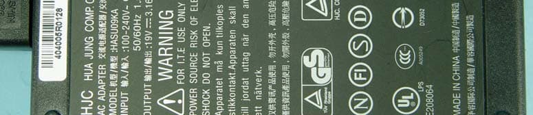
Click to zoom
Application Details
- Equipment Class
- DTS - Digital Transmission System
- Date of Grant
- Dec 16, 2004
- Application Purpose
- Original Equipment
- Date of Application
- Dec 16, 2004
- Equipment Note
- 10.4" Portable Wireless Thin Client
- Frequency Range
- 2412.00000000 - 2462.00000000
- Company
- Abocom Systems Inc
- Country
- Taiwan
Documents & Files
Document Text
Text extracted from the exhibit documents filed with the FCC. Open a document above to read the original.
Users Manual
REGULATORY NOTICES Federal Communications Commission Notice This equipment has been tested and found to comply with the limits for a Class B digital device, pursuant to Part 15 of the FCC Rules. These limits are designed to provide reasonable protection against harmful interference in a residential installation. This equipment generates, uses, and radiates radio frequency energy and, if not installed and used in accordance with the instructions, may cause harmful interference to radio communications. However, there is no guarantee that interference will not occur in a particular installation. CAUTION! CAUTION! Danger of explosion if an improper battery is substituted. If a replacement is needed, only replace with a manufacturer issued battery pack. Do not dispose of the battery pack in a fire. They may explode. Check with local authorities for proper disposal instructions. T ABLE OF CONTENTS 1. GETTING STARTED............................................................. 1 1.1. WELCOME.................................................................................. 1 1.2. SAFETY INSTRUCTIONS AND CARE OF YOUR WIRELESS THIN CLIENT.................................................................................................. 1 1.3. CHECKLIST................................................................................. 3 2. GETTING TO KNOW YOUR WIRELESS THIN CLIENT 5 2.1. P ARTS NAMES............................................................................ 5 2.2. THE CRADLE (OPTIONAL)........................................................... 8 2.3. T HE BATTERY AND AC ADAPTER.............................................. 9 2.4. THE STYLUS............................................................................. 10 2.5. TOUCH-SCREEN DISPLAY.......................................................... 11 2.6. DISPLAY PROPERTIES............................................................... 11 2.7. T HE CRADLE (OPTIONAL)......................................................... 11 3. MANAGING YOUR INFORMATION............................... 12 3.1. D ATA INPUT............................................................................. 12 Software Keyboard .................................................................. 12 3.2. D ATA SYNCHRONIZATION........................................................ 13 4. CONNECTING OTHER DEVICES ................................... 22 5. GETTING ONLINE.............................................................. 23 6. TROUBLESHOOTING ........................................................ 24 - 1 - 1. Getting Started 1.1. Welcome Congratulations! With your new Wireless Thin Client you will be able to create, manage and share information, send and receive email, and carry out research from virtually anywhere! Your Wireless Thin Client gives you freedom; easy access to the Internet, and the 800X600 SVGA screen offers high resolution for all your Tablet uses. This manual will guide you through the Tablet’s simple set-up, introduce you to its range of features and help you source extra information. 1.2. Safety Instructions and Care of your Wireless Thin Client CAUTION! Danger of explosion if an improper battery is substituted. If a replacement is needed, only replace with a manufacturer issued battery pack. • During normal usage and charging, the battery pack heats up. This is caused by energy that has been generated and a chemical charge that has occurred inside the battery pack. This is not a cause for concern. • You should charge batteries at temperatures from 10°C to 30°C (from 50 °F to 85 °F). Lower temperatures require a longer charging time. - 2 - • Do not carry a battery in your pocket, purse, or other container where metal objects could short-circuit the battery pack. The resulted excessive current flow can cause extremely high temperatures and may result in damage from burns. • Do not use your Wireless Thin Client in a wet environment, for instance, near a bathtub, sink, or any other place where there is risk of moisture. • To help prevent electric shock, plug the AC adapter into a three prong, grounded power source. If a two-prong extension plug is absolutely needed, use a 3-wire cable with properly grounded plugs. • If your Wireless Thin Client includes a modem PC Card, disconnect the modem cable during electrical storms to avoid the remote risk of electrical shock from lightening via the telephone line. • PC Cards may increase in temperature over an extended period of use. Use care in handling these cards. Do not dispose of the battery pack in a fire. They may explode. Check with local authorities for-proper disposal instructions. • When traveling, never check your Wireless Thin Client as baggage. You can put your Wireless Thin Client through an Xx- ray security machine, but never put your Wireless Thin Client through a metal detector. Have a charged battery with you in case you are asked to turn on the Tablet. • When traveling, do not place the Wireless Thin Client in an overhead compartment where it can slide around. Do not drop your Wireless Thin Client or subject it to mechanical shocks. • Protect your Wireless Thin Client from environmental hazards such as dirt, dust, food, liquids, temperature extremes, and over exposure to sunlight. - 3 - • When you change environments rapidly, in respect to temperature and humidity, with your Wireless Thin Client, condensation may form on or within the Tablet. To avoid potential damage to your Wireless Thin Client, allow sufficient time for the moisture to evaporate before using. • When disconnecting cables from your Wireless Thin Client, be sure to pull on the connector or the strain relief loop, not on the cable itself. As you pull, keep it evenly aligned to avoid bending the connector pins. Never force a connector into a port. Make sure the connector and port are aligned correctly. • Before you clean your Wireless Thin Client, turn it off, remove the battery, and unplug the power source. • Cl…
Text truncated - open the document above for the full version.
External Photos
Page 1 CONSTRUCTION PHOTOS OF EUT Page 2 Page 3 Page 4 Page 5 Page 6 Page 7 Page 8 Page 9 Page 10 Page 11 Page 12
ID Label/Location Info
FCC ID Label Location
ID Label/Location Info
FJ2500 MODEL NO.: FJ25P Series AboCom Systems, Inc. MADE IN TAIWAN INPUT : 19V --- 3.16A M75-1WN02-000 FOR USE WITH ADAPTER MODEL: HJC HASU09KA AboCom Systems, Inc. FJ25P AboCom Systems, Inc. MADE IN TAIWAN M75-1WN03-000 MODEL NO.: FJ25C INPUT : 19V --- 3.16A FOR USE WITH ADAPTER MODEL: HJC HASU09KA FCC ID : MQ4MFJ25P21J1 AboCom Systems, Inc. MODEL NO. : FJ25B 14.8V 2200mAh FINAL ASSEMBLY IN TAIWAN M75-1WN01-000 RISK OF EXPLOSION IF BATTERY IS REPLACED BY AN INCORRECT TYPE DISPOSE OF USED BATTERIES ACCORDING TO THE INSTRUCTIONS AboCom Systems, Inc. FJ25C AboCom Systems, Inc. FJ25B This device complies with Part 15 of the FCC Rules. Operation is subject to the following two conditions: (1) this device may not cause harmful interference, and (2) this device must accept any interference received, including interference that may cause undesired operation. This device complies with Part 15 of the FCC Rules. Operation is subject to the following two conditions: (1) this device may not cause harmful interference, and (2) this device must accept any interference received, including interference that may cause undesired operation.
Operational Description
FCC ID: MQ4MFJ25P21J1 Report No. RF931001A09 Operational Description This device is a 10.4” Portable Wireless Thin Client which operates in the 2.4GHz frequency spectrum with throughput of up to 54Mbps which OFDM technique will be applied. If the signal to noise radio is too poor which could not support 54Mbps, the 11Mbps data rate with CCK technique will be applied. The transmitter of the EUT is powered by AC adapter. The antenna is PIFA antenna with UFL connector. Under normal use condition, the user has to keep at least 20cm separation distance between radiator and the body of the user. The other instruction, please have a look at the users manual.
RF Exposure Info
FCC ID: MQ4MFJ25P21J1 Report No: SA931001A09 1 RF EXPOSURE REPORT REPORT NO.: SA931001A09 MODEL NO. : FJ25P21U1, FJ25C11 SERIES MODEL NO.: FJ25XXXXX ACCORDING: FCC Guidelines for Human Exposure IEEE C95.1 APPLICANT: AboCom Systems, Inc. ADDRESS: 1F, No.21, Yanfa 2nd Rd., SBIP, Hsinchu City 300, Taiwan, R.O.C. ISSUED BY: Advance Data Technology Corporation TEST LOCATION: No. 19, Hwa Ya 2nd Rd., Wen Hwa Tsuen, Kwei Shan Hsiang, Taoyuan Hsien 333, Taiwan, R.O.C. FCC ID: MQ4MFJ25P21J1 Report No: SA931001A09 2 RF Exposure Measurement (Portable Device) 1. Introduction In this document, we try to prove the safety of radiation harmfulness to the human body for our product. The limit for Maximum Permissible Exposure (MPE) specified in FCC 1.1310 is followed. The Gain of the antenna used in this product is measured in a Fully Anechoic Chamber (FAC) calibrated for antenna measurement in ADT, and also the maximum total power input to the antenna is measured. Through the Friis transmission formula and the maximum gain of the antenna, we can calculate the distance, away from the product, where the limit of MPE is reached. Although the Friis transmission formula is a far field assumption, the calculated result of that is an over-prediction for near field power density. We will take that as the worst case to specify the safety range. 2. RF Exposure Limit According to FCC 1.1310: The criteria listed in the following table shall be used to evaluate the environmental impact of human exposure to radio-frequency (RF) radiation as specified in 1.1307(b) LIMITS FOR MAXIMUM PERMISSIBLE EXPOSURE (MPE) Frequency Range (MHz) Electric Field Strength (V/m) Magnetic Field Strength (A/m) Power Density (mW/cm 2 ) Average Time (minutes) (A)Limits For Occupational / Control Exposures 300-1500......F/3006 1500-100,000......56 (B)Limits For General Population / Uncontrolled Exposure 300-1500......F/15006 1500-100,000......1.030 F = Frequency in MHz FCC ID: MQ4MFJ25P21J1 Report No: SA931001A09 3 3. Friis Formula Friis transmission formula: Pd = (Pout*G) / (4*pi*r 2 ) where Pd = power density in mW/cm 2 Pout = output power to antenna in mW G = gain of antenna in linear scale Pi = 3.1416 R = distance between observation point and center of the radiator in cm If we know the maximum Gain of the antenna and the total power input to the antenna, through the calculation, we will know the MPE value at distance 20cm. Ref.: David K. Cheng, Field and Wave Electromagnetics, Second Edition, Page 640, Eq. (11-133). 4 EUT Operating condition The software provided by Manufacturer enabled the EUT to transmit and receive data at lowest, middle and highest channel individually. 5. Classification This device is not fixed inside the host equipment that is classified as Portable Device. FCC ID: MQ4MFJ25P21J1 Report No: SA931001A09 4 6 Conclusion No Evaluation Required if power is below this threshold: F(GHz)mW Low2.412 High2.462 24.62 Maximum measured transmitter power: Pout (dBm)Pout (mW) Conducted Power12.5317.9 EIRP Power13.3721.73 *Note: The antenna is PIFA antenna with 0.84dBi gain Threshold for no SAR evaluation is 24.62mW Transmitter power is 21.73mW Conclusion: No SAR evaluation required since Transmitter Pout is below FCC threshold
Test Report
FCC ID: MQ4MFJ25P21J1 Report No.: RF931001A091Issued: Dec. 06, 2004 FCC TEST REPORT REPORT NO.: RF931001A09 MODEL NO.: FJ25P21U1, FJ25C11 SERIES MODEL NO.: FJ25XXXXX (refer to the note 3 and 4 of page 7 for other models) RECEIVED: Nov. 04, 2004 TESTED: Nov. 19 ~ Dec. 02, 2004 APPLICANT: AboCom Systems, Inc. ADDRESS: 1F, No.21, Yanfa 2nd Rd., SBIP, Hsinchu City 300, Taiwan, R.O.C. ISSUED BY: Advance Data Technology Corporation LAB ADDRESS: No. 47, 14th Ling, Chia Pau Tsuen, Lin Kou Hsiang 244, Taipei Hsien, Taiwan, R.O.C. TEST LOCATION: No. 19, Hwa Ya 2 nd Rd., Wen Hwa Tsuen, Kwei Shan Hsiang, Taoyuan Hsien 333, Taiwan, R.O.C. This test report consists of 94 pages in total. It may be duplicated completely for legal use with the approval of the applicant. It should not be reproduced except in full, without the written approval of our laboratory. The client should not use it to claim product endorsement by CNLA, A2LA or any government agencies. The test results in the report only apply to the tested sample. 0528 ILAC MRA FCC ID: MQ4MFJ25P21J1 Report No.: RF931001A092Issued: Dec. 06, 2004 Table of Contents 1CERTIFICATION ..................................................................................................................... 4 2SUMMARY OF TEST RESULTS ............................................................................................ 5 2.1MEASUREMENT UNCERTAINTY .......................................................................................... 6 3GENERAL INFORMATION ..................................................................................................... 7 3.1GENERAL DESCRIPTION OF EUT ....................................................................................... 7 3.2DESCRIPTION OF TEST MODES ......................................................................................... 8 3.3GENERAL DESCRIPTION OF APPLIED STANDARDS ........................................................ 8 3.4DESCRIPTION OF SUPPORT UNITS ................................................................................... 9 3.5CONFIGURATION OF SYSTEM UNDER TEST .................................................................... 9 4TEST TYPES AND RESULTS............................................................................................... 10 4.1CONDUCTED EMISSION MEASUREMENT ....................................................................... 10 4.1.1LIMITS OF CONDUCTED EMISSION MEASUREMENT..................................................... 10 4.1.2TEST INSTRUMENTS ..........................................................................................................10 4.1.3TEST PROCEDURES............................................................................................................11 4.1.4DEVIATION FROM TEST STANDARD..................................................................................11 4.1.5TEST SETUP ........................................................................................................................ 12 4.1.6EUT OPERATING CONDITIONS ......................................................................................... 12 4.1.7TEST RESULTS .................................................................................................................... 13 4.2RADIATED EMISSION MEASUREMENT............................................................................. 25 4.2.1LIMITS OF RADIATED EMISSION MEASUREMENT .......................................................... 25 4.2.2TEST INSTRUMENTS ..........................................................................................................26 4.2.3TEST PROCEDURES...........................................................................................................27 4.2.4DEVIATION FROM TEST STANDARD................................................................................. 27 4.2.5TEST SETUP ........................................................................................................................ 28 4.2.6EUT OPERATING CONDITIONS ......................................................................................... 28 4.2.7TEST RESULTS .................................................................................................................... 29 4.2.8TEST RESULTS (A) .............................................................................................................. 34 4.2.9TEST RESULTS (B) .............................................................................................................. 43 4.36dB BANDWIDTH MEASUREMENT .................................................................................... 52 4.3.1LIMITS OF 6dB BANDWIDTH MEASUREMENT ................................................................. 52 4.3.2TEST INSTRUMENTS ..........................................................................................................52 4.3.3TEST PROCEDURE .............................................................................................................53 4.3.4DEVIATION FROM TEST STANDARD................................................................................. 53 4.3.5TEST SETUP ........................................................................................................................ 53 4.3.6EUT OPERATING CONDITIONS ......................................................................................... 53 4.3.7TEST RESULTS (A) .............................................................................................................. 54 4.3.8TEST RESULTS (B) .............................................................................................................. 58 4.4MAXIMUM PEAK OUTPUT POWER.................................................................................... 62 4.4.1LIMITS OF MAXIMUM PEAK OUTPUT POWER MEASUREMENT .................................... 62 FCC ID: MQ4MFJ25P21J1 Report No.: RF931001A093Issued: Dec. 06, 2004 4.4…
Text truncated - open the document above for the full version.
Test Setup Photos
FCC ID: MQ4MFJ25P21J1 Report No.: RF931001A0988Issued: Dec. 06, 2004 5 PHOTOGRAPHS OF THE TEST CONFIGURATION CONDUCTED EMISSION TEST (Test Mode 1) FCC ID: MQ4MFJ25P21J1 Report No.: RF931001A0989Issued: Dec. 06, 2004 (Test Mode 2) FCC ID: MQ4MFJ25P21J1 Report No.: RF931001A0990Issued: Dec. 06, 2004 RADIATED EMISSION TEST (Test Mode 1 – X axis) FCC ID: MQ4MFJ25P21J1 Report No.: RF931001A0991Issued: Dec. 06, 2004 (Test Mode 1 – Y axis) FCC ID: MQ4MFJ25P21J1 Report No.: RF931001A0992Issued: Dec. 06, 2004 (Test Mode 1 – Z axis) FCC ID: MQ4MFJ25P21J1 Report No.: RF931001A0993Issued: Dec. 06, 2004 (Test Mode 2)
Contact Information
Applicant
Harry Huang(Manager)
Technical Contact
Advance Data Technology CorporationEllis Wu
[email protected]+886 3 318 3232
No. 19 Hwa Ya 2nd Rd. · Kueishan Taoyuan · Taiwan
Test Firm
Bureau Veritas CPS (H.K.) Ltd. Taoyuan BranchRichard Chen
Technical Specifications
| # | Rule Parts | Frequency Range | Power Output |
|---|---|---|---|
| 1 | 15C | 2.41 GHz - 2.46 GHz | 18.00 mW |
Other Applications from Abocom Systems Inc

MQ4WM5208
Oct 27, 2015802.11b/g/n Module
Equipment Class
DTS - Digital Transmission System
MQ4AM7221
Mar 18, 20152T2R 802.11b/g/n/ac Module
Equipment Class
DTS - Digital Transmission System
MQ4PLW72
Mar 18, 201511ac WiFi Extender Smart Plug / 11ac WiFi Extender
Equipment Class
NII - Unlicensed National Information Infrastructure TX
MQ4CB1522M
Sep 22, 2014IP Camera
Equipment Class
DTS - Digital Transmission System
MQ4-MBR-1100
Sep 21, 2014Android TV Dongle
Equipment Class
JBC - Part 15 Class B Computing Device/Personal Computer