MQ4SDW11GSDIO Wireless LAN Card
Abocom Systems Inc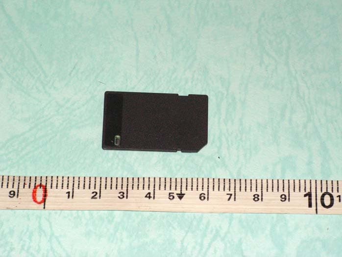
Click to zoom
Application Details
- Equipment Class
- DTS - Digital Transmission System
- Date of Grant
- Aug 16, 2006
- Application Purpose
- Original Equipment
- Date of Application
- Aug 16, 2006
- Equipment Note
- SDIO Wireless LAN Card
- Frequency Range
- 2412.00000000 - 2462.00000000
- Company
- Abocom Systems Inc
- Country
- Taiwan
Documents & Files
Document Text
Text extracted from the exhibit documents filed with the FCC. Open a document above to read the original.
Users Manual
1 INSTALLING THE DRIVER Installation of the SD WLAN Card Driver to the Pocket PC using Microsoft Active Sync® 1. Connect your PDA to your computer and make sure Active-Sync® has established a connection between the two devices. 2. Insert the included CD-ROM to your PC. The main screen will appear, click Install Driver to start driver installation. 2 Note: Do not insert the SD WLAN Card into the card slot of your PDA until the Driver installation has been performed. 3. Click “YES” to continue the installation. 4. Click “OK” to complete the driver installation. ACCESSING THE WLAN UTILITY 1. Insert the SDIO Wireless LAN Card into the SD slot of your PDA 2. Go to Start > Settings > Connections tab > Wireless Ethernet to access the Windows CE built-in WLAN utility 3 CONFIGURING WLAN UTILITY Select an available AP or router from the list and tap Connect to make a connection. 4 Wireless tab Wireless Network Select an available network device from the list and tap Connect. Network to access Select the type of network access from the pull-down list. All available: A group of wireless devices communicating with both access points and network adapters. Only access points: A group of wireless devices communicating directly with only access points. Only computer-to-computer: A group of wireless devices communicating directly with each other without the use of an access point. Automatically connect to non-preferred networks Tap the checkbox to enable this function, if the Automatically connect to non-preferred networks is enabled, your device will detect all the new networks for you to configure. 5 6 Network Adapters tab My network Card connects to Tap Work or The internet from the pull-down menu. Work: Connects to the network in your office. The internet: Connects to your ISP at home. Tap an adapter to modify settings Tap an adapter from the list to enter its configuration screen. If SDIO 802.11g Adapter is tapped, the following screen will appear for you to configure: 7 8 IP Address tab Use server-assigned IP address To use DHCP, tap User assigned-IP Address. The Wireless Router will act as a DHCP server. An IP Address will be obtained from the Wireless Router. 9 Use specific IP address IP Address: Enter the IP address (within the range of the wireless router’s IP address, for instance, if the IP address of the router which you wish to connect is 192.168.1.254, you may enter the IP address here from 192.168.1.1 to 192.168.1.253 ). Subnet mask: The Subnet Mask must be the same as that set on your Ethernet network. Default Gateway: Enter the IP address of your network’s gateway. The gateway is the device that enables communication between your computers and the Internet. In most cases, your router acts as your gateway. 10 11 Name Servers tab DNS Enter the IP address of your ISP's server, which translates the names of websites into IP addresses. Alt DNS The secondary IP address of your ISP’s server. WINS The Windows Internet Naming Service (WINS) converts NetBIOS names to IP addresses. If using a WINS server, please enter that server’s IP address. Otherwise, leave this field blank. Alt WINS The secondary IP address of your WIN server. M73-APO11-270 12 Federal Communication Commission Interference Statement This equipment has been tested and found to comply with the limits for a Class B digital device, pursuant to Part 15 of the FCC Rules. These limits are designed to provide reasonable protection against harmful interference in a residential installation. This equipment generates, uses and can radiate radio frequency energy and, if not installed and used in accordance with the instructions, may cause harmful interference to radio communications. However, there is no guarantee that interference will not occur in a particular installation. If this equipment does cause harmful interference to radio or television reception, which can be determined by turning the equipment off and on, the user is encouraged to try to correct the interference by one of the following measures: Reorient or relocate the receiving antenna. Increase the separation between the equipment and receiver. Connect the equipment into an outlet on a circuit different from that to which the receiver is connected. Increase the separation between the equipment and receiver. Connect the equipment into an outlet on a circuit different from that to which the receiver is connected. Consult the dealer or an experienced radio/TV technician for help. FCC Caution: Any changes or modifications not expressly approved by the party responsible for compliance could void the user's authority to operate this equipment. This device complies with Part 15 of the FCC Rules. Operation is subject to the following two conditions: (1) This device may not cause harmful interference, and (2) this device must accept any interference received, including interference that may cause undesired operation.
External Photos
SPORTON International Inc. PAGE NUMBER : A1 OF A1 TEL : 886-2-2696-2468 ISSUED DATE : Jun. 23, 2006 FAX : 886-2-2696-2255 APPENDIX A. Photographs of EUT
Internal Photos
SPORTON International Inc. PAGE NUMBER : A1 OF A2 TEL : 886-2-2696-2468 ISSUED DATE : Jun. 23, 2006 FAX : 886-2-2696-2255 APPENDIX A. Photographs of EUT SPORTON International Inc. PAGE NUMBER : A2 OF A2 TEL : 886-2-2696-2468 ISSUED DATE : Jun. 23, 2006 FAX : 886-2-2696-2255
Test Report
SPORTON International Inc. No. 52, Hwa Ya 1st Rd., Kwei-Shan Hsiang, TaoYuan Hsien, Taiwan, R.O.C. Ph: 886-3-327-3456 / FAX: 886-3-327-0973 / www.sporton.com.tw Report Format Version: RF-15.247-2006-2-17-d FCC RADIO TEST REPORT Applicant’s company AboCom Systems, Inc Applicant Address No.77, Youyi Rd., Jhunan Township, Miaoli Country 350, Taiwan FCC ID MQ4SDW11G Manufacturer’s company AboCom Systems, Inc Manufacturer Address No.77, Youyi Rd., Jhunan Township, Miaoli Country 350, Taiwan Product Name SDIO Wireless LAN Card Brand Name AboCom Model Name SDW11G Test Rule 47 CFR FCC Part 15 Subpart C § 15.247 Test Freq. Range 2400 ~ 2483.5MHz Receive Date May 15, 2006 Test Date Jun. 06, 2006 Submission Type Original Equipment Statement Test result included is only for the 802.11b/g part of the product. The test result in this report refers exclusively to the presented test model / sample. Without written approval of SPORTON International Inc., the test report shall not be reproduced except in full. The measurements and test results shown in this test report were made in accordance with the procedures and found in compliance with the limit given in ANSI C63.4-2003 and 47 CFR FCC Part 15 Subpart C. The test equipment used to perform the test is calibrated and traceable to NML/ROC. Lab Code: 200079-0 Report No.: FR650607-02 Report Format Version: RF-15.247-2006-2-17-d Page No. : i of ii FCC ID: MQ4SDW11G Issued Date : Jul. 20, 2006 Table of Contents 1. CERTIFICATE OF COMPLIANCE ......................................................................................................................... 1 2. SUMMARY OF THE TEST RESULT .......................................................................................................................... 2 3. GENERAL INFORMATION .................................................................................................................................. 3 3.1. Product Details....................................................................................................................................................................................3 3.2. Table for Filed Antenna.......................................................................................................................................................................3 3.3. Table for Carrier Frequencies .............................................................................................................................................................3 3.4. Table for Test Modes ...........................................................................................................................................................................4 3.5. Table for Testing Locations..................................................................................................................................................................4 3.6. Table for Supporting Units ...................................................................................................................................................................4 3.7. Table for Parameters of Test Software Setting .....................................................................................................................................5 3.8. Test Configurations .............................................................................................................................................................................5 4. TEST RESULT ..................................................................................................................................................... 7 4.1. AC Power Line Conducted Emissions Measurement...........................................................................................................................7 4.2. Maximum Peak Output Power Measurement ...................................................................................................................................11 4.3. Power Spectral Density Measurement ..............................................................................................................................................13 4.4. 6dB Spectrum Bandwidth Measurement ..........................................................................................................................................18 4.5. Radiated Emissions Measurement ....................................................................................................................................................23 4.6. Band Edge Emissions Measurement .................................................................................................................................................41 4.7. Antenna Requirements .....................................................................................................................................................................48 5. LIST OF MEASURING EQUIPMENTS ................................................................................................................... 49 6. SPORTON COMPANY PROFILE ........................................................................................................................ 51 6.1. Test Location.....................................................................................................................................................................................51 7. NVLAP CERTIFICATE OF ACCREDITATION ......................................................................................................... 52 APPENDIX A. PHOTOGRAPHS OF EUT.......................................................................................................... A1 ~ A3 APPENDIX B. TEST PHOTOS.......................................................................................................................... B1 ~ B7 Report No.: FR650607-02 Report Format Version: RF-15.247-2006-2-17-d Page No. : ii of ii FCC ID: MQ…
Text truncated - open the document above for the full version.
Test Setup Photos
Report No.: FR650607-02 FCC ID: MQ4SDW11G Page No. : B1 of B7 Appendix B. Test Photos Report No.: FR650607-02 FCC ID: MQ4SDW11G Page No. : B2 of B7 1. Photographs of Conducted Emissions Test Configuration FRONT VIEW REAR VIEW Report No.: FR650607-02 FCC ID: MQ4SDW11G Page No. : B3 of B7 Report No.: FR650607-02 FCC ID: MQ4SDW11G Page No. : B4 of B7 2. Photographs of Radiated Emissions Test Configuration Below 30MHz FRONT VIEW REAR VIEW Report No.: FR650607-02 FCC ID: MQ4SDW11G Page No. : B5 of B7 Test Configuration : 30MHz ~1GHz FRONT VIEW REAR VIEW Report No.: FR650607-02 FCC ID: MQ4SDW11G Page No. : B6 of B7 Test Configuration : Above 1GHz FRONT VIEW REAR VIEW Report No.: FR650607-02 FCC ID: MQ4SDW11G Page No. : B7 of B7
Contact Information
Applicant
Harry Huang(Manager)
Technical Contact
Sporton International Inc.Wayne Hsu
No. 52. Hwa Ya 1st Rd., Hwa Ya Technology Park · Tao Yuan · Taiwan
Test Firm
Sporton International Inc.Kathy Lin
Technical Specifications
| # | Rule Parts | Frequency Range | Power Output |
|---|---|---|---|
| 1 | 15C | 2.41 GHz - 2.46 GHz | 15.50 mW |
Other Applications from Abocom Systems Inc

MQ4WM5208
Oct 27, 2015802.11b/g/n Module
Equipment Class
DTS - Digital Transmission System
MQ4AM7221
Mar 18, 20152T2R 802.11b/g/n/ac Module
Equipment Class
DTS - Digital Transmission System
MQ4PLW72
Mar 18, 201511ac WiFi Extender Smart Plug / 11ac WiFi Extender
Equipment Class
NII - Unlicensed National Information Infrastructure TX
MQ4CB1522M
Sep 22, 2014IP Camera
Equipment Class
DTS - Digital Transmission System
MQ4-MBR-1100
Sep 21, 2014Android TV Dongle
Equipment Class
JBC - Part 15 Class B Computing Device/Personal Computer